Invacare EC-Track Installation & Technical Description
- Typ
- Installation & Technical Description

Invacare® EC-Track®
Installation & Technical Description,
Installation og teknisk beskrivelse,
Installation et description technique,
Montering og teknisk beskrivelse,
Montering och teknisk beskrivning
enRailsystemforceilinghoistRobin®/Robin
Mover®
ServiceManual................................3
daSkinnesystemtilRobin®/RobinMover®
løftemotor
Servicemanual.................................29
frSystèmederailspourlève-personnesurrail
Robin®/RobinMover®
Manueldemaintenance........................55
no
SkinnesystemfortakmontertRobin®-/Robin
Mover®-løfter
Servicehåndbok................................83
svSkensystemförtaklyftenRobin®/RobinMover®
Servicemanual.................................109
PROVIDER:Keepthismanual.
TheproceduresinthismanualMUSTbeperformedbyaqualied
technician.

©2019InvacareCorporation
Allrightsreserved.Republication,duplicationormodicationinwholeorinpartisprohibitedwithoutpriorwritten
permissionfromInvacare.Trademarksareidentiedby™and®.AlltrademarksareownedbyorlicensedtoInvacare
Corporationoritssubsidiariesunlessotherwisenoted.

Contents
1General.........................................4
1.1Aboutthismanual..............................4
1.2GeneralSafety.................................4
1.3WarrantyInformation...........................4
2Railsystem......................................5
2.1Singlerailsystem..............................5
2.2Traversesystem................................6
2.3RoomTransfer.................................7
2.4Rails,Brackets&Accessories......................8
3Installation.......................................14
3.1GeneralInstallationInstructions....................14
3.2CeilingMountingSystem.........................14
3.2.1ConcreteCeiling.............................14
3.2.2ConcreteCeilingwithSuspendedCeiling...........15
3.2.3WoodenCeiling.............................17
3.3Wallinstallation–endhungrail...................18
3.3.1RailproleMandL..........................18
3.4Wallinstallation–sidehungbracketorside/endhung
bracket.....................................19
3.5Curves......................................19
3.6Railcoupling..................................20
3.6.1RailcouplingforproleMandL................20
3.6.2RailcouplingforproleS......................20
3.7Wallsupportlegs..............................20
3.8Mountingtraversesystem........................21
3.9Installationoftrackswitches......................22
3.10Transitcoupling...............................22
3.10.1Adjustingtheholeinthewall/dooropening.......22
3.10.2Installingthetransitcoupling..................23
3.10.3Installingandconnectingcontrolbuttonand
powersupply..............................24
3.10.4Installingatraversesystemwithlockxturefor
transitcoupling.............................24
3.10.5Installationofasinglerailforacouplingsystem....24
3.10.6Mountingthepositioningxturesonparallelrail
S-proleandM/L-proles.....................24
3.11Installingtheceilinghoisttotherailsystem..........25
3.11.1InstallingRobin®............................25
3.11.2InstallingRobin®Mover......................26
3.12Inspection/checkoftherailsystem...............26
4TechnicalData....................................28
4.1Therailsystem................................28
4.2Dimensionsfordifferenttrackinstallations............28

Invacare®EC-Track®
1General
1.1Aboutthismanual
Thisinstallationmanualisintendedasaninstructionwhen
planningandcarryingouttheinstallation.Inorderto
ensuresafetywhenhandlingtheproduct,readthemanual
carefullyandfollowthesafetyinstructions.
Forpre-saleanduserinformation,pleaseseetheuser
manual.FindtheusermanualonInvacare’swebsiteor
contactyourInvacarerepresentative(seeaddressesatthe
endofthismanual).
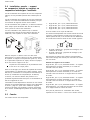
Symbolsinthismanual
Inthismanual,hazardsareindicatedbysymbols.The
symbolsareaccompaniedbyasignalwordthatindicates
theseverityoftherisk.
WARNING
Indicatesahazardoussituationthatcould
resultinseriousinjuryordeathifitisnot
avoided.
CAUTION
Indicatesahazardoussituationthatcould
resultinminororslightinjuryifitisnot
avoided.
IMPORTANT
Indicatesahazardoussituationthatcould
resultindamagetopropertyifitisnot
avoided.
TipsandRecommendations
Givesusefultips,recommendationsand
informationforefcient,trouble-freeuse.
Givesinformationabouttherequiredtools.
ThisproductfeaturestheCEmark,in
compliancewiththeMedicalDevice
Regulation2017/745Class1.Thelaunchdate
ofthisproductisstatedintheCEdeclaration
ofconformity.
1.2GeneralSafety
WARNING!
Safetyrulesbeforeinstallation
–Allinstallationsmustcomplywiththenational
rulesandstandards.
–Useonlyapprovedinstallationcomponents.
–Ateverypointofsuspension,theroof/ceiling
structuremustbeabletowithstandastatic
loadofatleast300kg.
–Beforemountingarailsystem,theroof,
walls,andoormustbeexaminedcarefully.
Determinetheexactmaterialsinvolvedinthe
roofandwalls.Thisexaminationmustonly
becarriedoutbyasuitablyqualiedperson.
–Therailsystemmustbemountedonlyby
suitablyqualiedpersons.
StressTest
InaccordancewiththeEuropeanstandardEN10535,the
systemshallbestresstestedwith300kg.Thisshouldbe
doneateachxingpoint.Thistestistobecarriedout
asatestingofthesubstratum’sabilitytokeeptherail
systeminplace.Thistestshallbecarriedoutbyasuitably
qualiedperson.
1.3WarrantyInformation
Termsandconditionsofthewarrantyarepartofthe
generaltermsandconditionsparticulartotheindividual
countriesinwhichthisproductissold.
ContactinformationforyourlocalInvacareofceislocated
insidethebackcoverofthismanual.
4
1586749-C

Railsystem
2Railsystem
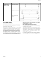
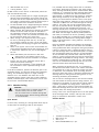
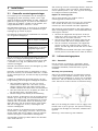
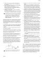
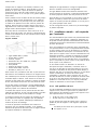
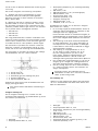
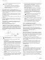
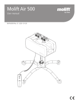
2.1Singlerailsystem
Asinglerailsystemissuitedinsituationswherethelifting
isdoneatspecicorlimitedplaces(e.g.underneaththe
track).
Asinglerailsystemconsistsofonestraightrail.Thisrail
maybemountedparalleltothewallsordiagonallyinthe
room.
Therailsystemcanbeoptionallyextendedwithcurves
withanglesof30°,45°,60°and90°.
Therailsystemcanbeinstalledonthewallortheceiling.
Withasinglerailsystemitispossibletohidethe
installationintheceilingsothatonlytheopeningofthe
railisvisible.
1586749-C5

Invacare®EC-Track®
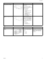
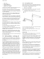
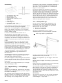
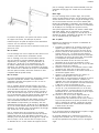
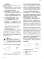
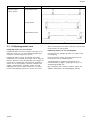
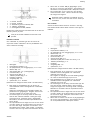
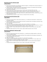
2.2Traversesystem
Atraversesystemissuitedforcaseswhenanunlimitednumberofliftingplacesisrequiredintheroom.
Atraversesystemconsistsoftwoparallelrailsmountedontheceilingorthewall.Ineachparallelrail,atraversetrolleyis
insertedwitchcantravelthefulllengthoftheparallelrails,fromendstoptoendstop.
Acrosstheparallelrailsatraverserailismountedtothetwotraversetrolleys.Thisinstallationcanbecarriedoutin
differentways,asshownintheillustrationsbelow.Withahoisttrolleyinsertedinthetraverserail,thehoistcantravel
thefulllengthofthetraverserail.
Thesystempermitsanunlimitednumberofliftingplaces,sincethetraversesystemcoverstheentireroom.
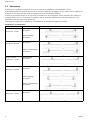
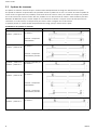
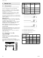
Combinationsoftraversesystems
RailsCombinationPossiblecombinations
Parallel:S-Prole
Traverse:S-Prole
Under-hungtraverse:
Between-hungtraverse:
Parallel:S-Prole
Traverse:M-Prole
Under-hungtraverse:
Partlybetween-hung
traverse:
Parallel:S-Prole
Traverse:L-Prole
Under-hungtraverse:
Parallel:M-Prole
Traverse:M-Prole
Under-hungtraverse:
Between-hungtraverse:
Partlybetween-hung
traverse:
Parallel:M-Prole
Traverse:L-Prole
Under-hungtraverse:
61586749-C

Railsystem
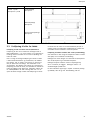
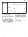
RailsCombinationPossiblecombinations
Parallel:L-Prole
Traverse:L-Prole
Under-hungtraverse:
Between-hungtraverse:
Partlybetween-hung
traverse:
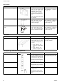
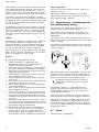
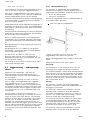
2.3RoomTransfer
Roomtransferwithtwohoists
RoomtransfercanbedonebyusingtwoRobinhoists;
oneineachroom.Toeasethisoperation,anInvacare
room-to-roomtrolleyisused.
Roomtransferispossibleinbothsingle-orroomcovering
installations.Itisimportantthattherailsarelocated
asclosetothedoorwayaspossible.Wheninstallinga
roomcoveringrailsystemintendedforroomtransfer,
thetraverserailmustbeinstalledperpendiculartothe
wallwiththedoorway.Thedistancebetweenthetwo
endstopbuffersmustnotexceed600mm.Toobtainthe
bestpossibleresultduringroomtransfer,theremustbea
minimumdistanceof1.85mbetweentheoorandthe
undersideofthehoist.Thismustbekeptinmindduring
installationoftherailsystem.
Roomtransferwithtransit(transitcoupling)
Asanalternativetheroomtransfercanbeachievedby
aninstalledtransitcoupling.
Thecouplingcanbeusedtoconnecteithertwotraverse
systemsoronetraversesystemandonesinglerailsystem.
Thecouplingisoperatedelectricallybyacontrolbutton
mountedonthewall.Thecouplingisdeliveredwitha
standardlengthof800mm.
Forfurtherinformationseechapters2.4Rails,Brackets&
Accessories,page8and3.10Transitcoupling,page22.
1586749-C
7

Invacare®EC-Track®
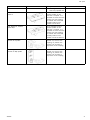
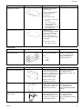
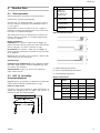
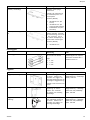
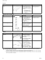
2.4Rails,Brackets&Accessories
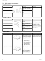
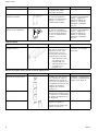
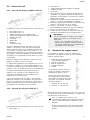
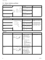
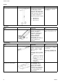
RailprolesS,M,L
Type
Description
Info
RailproleSMax.length=7.8m
Max.spanwithoutsupport:
2m
RailproleMMax.length=7.8m
Max.spanwithoutsupport:
4m
RailproleLMax.length=7.8m
Max.spanwithoutsupport:
8m
color:white
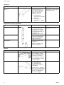
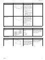
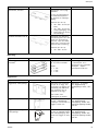
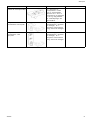
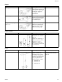
Curves30°,45°,60°,90°
Type
Description
Info
Curve30°
RailproleSwithcurve30°
and2x200mmstraightrail
Curve45°
RailproleSwithcurve45°
and2x200mmstraightrail
Curve60°
RailproleSwithcurve60°
and2x200mmstraightrail
Curve90°
RailproleSwithcurve90°
and2x600mmstraightrail
Allcurveshavearadiusof
400mm.
Allcurvesaresupplied
asrightorleftcurves.
Characteristicsforrightand
left,seechapter3.5Curves,
page19
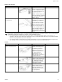
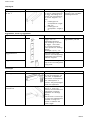
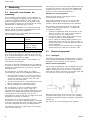
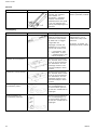
Ceilingbrackets
Type
Description
Info
Ceilingbracket,QuickCeilingbracketswithhidden
xingparts.Tobeused
forceilinginstallationof
single-railandtraverse
systems.
Sizes(WxDxH):
•30x68x14mm
(forcurves)
•70x68x14mm
(forordinaryceiling
supension)
•120x68x14mm
(forrailcoupling)
Installation:Seechapter3.2
CeilingMountingSystem,
page14.
Ceilingbracket,Quick,
Traverse
Bracketsfortraverse
systemandsidehung
wallinstallation
Thebracketismounted
beneaththetraversetrolley,
attheunderhungandpartly
between-hungtraverse
assembly.
81586749-C

Railsystem
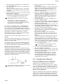
Type
Description
Info
Ceilingbracket,StandardCeilingbracketswithvisible
xingparts
Tobeusedforceiling
installationofsingle-railand
traversesystems.
Sizes(WxDxH):
•30x146x14mm(for
curves)
•70x146x14mm(for
ordinaryceiling
supension)
•120x146x14mm(for
railcoupling)
Standardceilingbracketwith
lock
Ceilingbracketwithlock
screwmeasuring(70x146).
Usedforceilinginstallation,
withmin.1perstraight
rail.Thisensuresthatthe
railisnotdisplacedafter
installation.
Sizes(WxDxH):
•70x146x14mm
Shims
Type
Description
Info
Shimforstandardceiling
bracket
Availableforceilingbrackets
in30,70,120mmwidth.
Height:
•1mm
•3mm
•5mm
Shimsaretobeusedin
installationstocompensate
possibledifferencesofthe
heightintheroof/ceiling
structure.
1586749-C9

Invacare®EC-Track®
Wallbrackets
Type
Description
Info
Wallbracket,endhungTobeusedwheninstalling
trackstoawall.Theycanbe
usedwhenthewallshave
sufcientlyhighcarrying
capacitywhenmounting
straightanddiagonallytoa
wall.
Tobeusedwithinserttubes
andconsole.
Installation:Seechapter3.3
Wallinstallation–endhung
rail,page18.
Wallbrackets,sidehungTobeusedwheninstalling
trackssidehung.Canbe
appliedifthewallhas
sufcientstrength.
Installation:Seechapter3.4
Wallinstallation–sidehung
bracketorside/endhung
bracket,page19
Wallbracket,sideandend
hung
Tobeusedwheninstalling
trackseithersideorend
hung.Canbeappliedifthe
wallhassufcientstrength.
Installation:Seechapter3.4
Wallinstallation–sidehung
bracketorside/endhung
bracket,page19
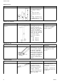
Inserttubes
Type
Description
Info
InserttubeforrailproleM
orL
Tobeusedwhenmounting
railendhungtowall,when
couplingtworails,orwhen
mountingrailsdiagonallyin
aroom.
•Inserttubeforrail
proleM:Length800
mm.
•Inserttubeforrail
proleL:Length1m.
Inserttubeissupplied
dependingontheparticular
mountingsituation.
Wallsupportleg,consoleandwallsupportfoot
Type
Description
Info
WallsupportlegTobeusedifthewalldoes
nothavesufcientcarrying
capacitywhenmountingthe
railtothewall.Maybeused
forthemonorailsystemsas
wellasthetraversesystems.
Leglength:2.6m/3m
Installation:Seechapter3.7
Wallsupportlegs,page20
WallsupportconsoleTheconsoleisalsoused
togetherwiththeendhung
wallbracketwhenmounting
straightordiagonal.
WallsupportfootLowfootforroomswithout
skirtingboard
Highfootforroomswith
skirtingboardpanalongthe
oor
101586749-C

Railsystem
EndStop
Type
Description
Info
Endstop Theendstopismounted
atallrailoutlets,which
ensuresthatthetrolleysdo
notleavetherailsystem.
Whentheendstopis
mounted,therubberplugis
tofacetowardsthetrolley.
endstopfortraverserail Whenthetraversesystemis
between-hung,thetraverse
railsendstopistobe
mountedinthetraverse
trolley.
Whentherailsaremounted
toawall,theendstopisto
beplacedsofarintotherail
thatthehoistdoesnothit
thewall
Insomecountries/localareasthereisademandfordoublesecuringoftheendstops.Suchextrasecuringcanbe
achievedbyinstallingoneofthefollowing:
•M5x16mmthreadformingscrew(e.g.Bufab/SweboltMRXorequal),10mmfromeachendoftherail,25mm
fromtherailunderside(thescrewcanbeinstalledinapre-drilledholeØ4,3mm).
•Ø6,3x22mmthreadformingscrew(e.g.Bufab/SweboltR6Borequal),10mmfromeachendoftherail,18
mmfromtherailunderside.
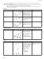
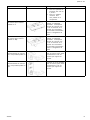
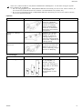
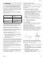
Trolleys
Type
Description
Info
HoistTrolley
The hoist trolley is used for
individual mono rail systems
as well as traverse systems.
The hoist trolley is used
when a Robin ceiling hoist is
to be mounted in the track
system.
TraverseTrolley Thetraversetrolleyisused
whenmountingatraverse
system.Foratraverse
system,2traversetrolleys
arealwaysused.
Room-To-RoomTrolley Theroom-to-roomtrolleyis
usedwhenatransferfrom
oneroomtoanotheris
required,typicallythrougha
doorway.
1586749-C
11

Invacare®EC-Track®
RailEndPlugs
Type
Description
Info
RailendplugS,M,LRailendplugsaresupplied
forrailprolesof3sizes.
Color:white.
Tobeusedattheclosureof
bothendsofallrails.
Mounting:Pressintotherail
proleaftertherailsystem
ismounted.
Pendles
Type
Description
Info
Pendles,adjustablePendlesareappliedifthere
isaneedforinstallinga
lowerrailsystemthanthe
originalceilinglevel.Canbe
usedinhiddeninstallationas
wellasvisibleinstallations.
Sizes(adjustablelength):
•200–300mm
•280–460mm
•440–740mm
Installation:See3.2.2
ConcreteCeilingwith
SuspendedCeiling,page15.
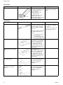
TrackSwitch
Type
Description
Info
Trackswitch,manualThetrackswitchismanually
operatedandisinstalled
withastandardceiling
bracket.Thetrackswitchis
usedincombinationwitha
ceilinginstalledsinglerail
systemwithS-prole,where
achangeindirectionis
requiredduringmovement
ofthepatient.
Installation:Seechapter3.9
Installationoftrackswitches,
page22
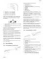
TransitCoupling
Type
Description
Info
TransitcouplingThetransitcouplingis
operatedelectricallyand
mountedwithpendlesin
theceilingonbothsidesof
thewall.Length:800mm.
Thecouplingisusedfor
movementofapatientfrom
oneroomtoanother.
•intraversesystemswith
S-,M,-andL-rails.
Controlbutton(forthe
wall),andatransformerare
enclosedwhendelivered.
Installation:Seechapter3.6
Railcoupling,page20
12
1586749-C

Railsystem
Type
Description
Info
•inasinglerailsystem
withonlyS-prolerails.
Lockxturefortraverse
proleS
Tobemountedonthe
traverseproleinthe
endthatiscoupled.Itis
mountedtoensurethatthe
traverserailandcoupling
arelockedandconnected
correctlybeforeroom
transfercanbedone.
Lockxturefortraverse
proleM/L
Tobemountedonthe
traverseproleinthe
endthatiscoupled.Itis
mountedtoensurethatthe
traverserailandcoupling
arelockedandconnected
correctlybeforeroom
transfercanbecarriedout.
Positioningxturesfor
parallelrailS-prole
Tobemountedonthe
parallelrail,closetothe
coupling,topositionthe
traverserailcorrectlyin
proportiontothecoupling.
Positioningxturesfor
parallelrailM/L-prole
Tobemountedonthe
parallelrail,closetothe
coupling,topositionthe
traverserailcorrectlyin
proportiontothecoupling.
1586749-C13

Invacare®EC-Track®
3Installation
3.1GeneralInstallationInstructions
Beforeinstallingarailsystem,acarefulandaccurate
measuringoftheroomisessential.Itisequallyimportant
todeterminetheconditionoftheceiling,thewallsand
theoorinordertodecidewhethertomounttherailson
theceilingoronthewalls.Next,youneedtodecidehow
manyliftingplacesareneededintheroom.
Whendeningtheliftingplaces,anindividualassessment
isrequired,whichtakesintoconsiderationthebuildofthe
individualuserandnumberofnurses.
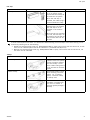
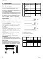
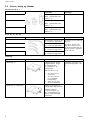
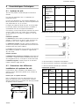
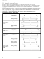
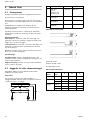
Thefollowingplacementoftypicalliftingplacesmaybe
usedasarecommendedguideline:
Bed1mfrominsideofthebed
headend
Toilet150mmfromthefront
edge
Bathtub
1/3wayup(sitting
position),½wayup
(recliningposition)
Changingtable1mfromtheheadendof
thetable
Whenmeasuringfortheselectedrailsystem,takeinto
considerationasuitableparkingplaceforthehoistwhenit
isnotinuse.Asuitablespotcouldbenearawall,where
thehoistchargerismountedonthewall.
Checkthecustomizedrailaswellasthebracketsandother
accessoriesagainstthedrawing.
Checkthatanyburrsandmetalshavingshavebeen
removedfromtherailstopreventthisdebrisfromgetting
stuckinthetrolleywheelsproducingnoiseanderratic
operation.
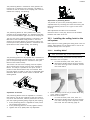
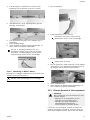
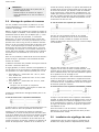
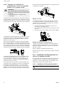
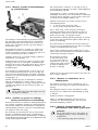
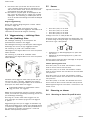
Incaseofsinglerailsandcurvedrailsneedingcoupling,
usetheenclosedpipepins.
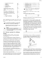
1.Pushthepipepinshalfwayintotheonerail.Holes
aredrilledtoØ3.2mmintherailthattheprevious
mentionedrailistobeconnectedto.Thenthenext
railisinsertedoverthepipepins.
2.Pushthenextrailintotheprotrudingpins.Donot
drillfurtherholesintherstrail.
3.Mountthebracketforrailcoupling.
When installing a traverse system where the parallel rails
are running from wall to wall, the minimum distance from
rail to wall must be 60 mm, insert the traverse trolley and
the rail end stop into the parallel rails before installation.
If not, the parallel rails must end min. 350 mm from the
wall to permit subsequently installation of the trolley.
When installing a mono rail system or a traverse rail in a
traverse system, it is important that the rail at one end
stops min. 160 mm from the wall to permit subsequently
installation of the hoist trolley.
At secondary installation of Robin Mover the distance
must be minimum 300 mm.
Wheninstallingrailswithbracketsdirectlyontheceiling,
makesurethattheceilingisevenandhorizontal.(Shims
ofrespectively1mm,3mmand5mmthickness,maybe
usedtoleveloutanyunevenness.)
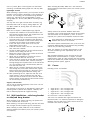
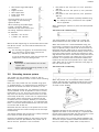
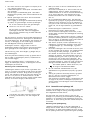
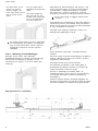
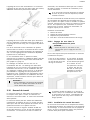
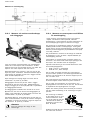
Keyholefortheinstallationpoint
AnyEC-Tracksystemmustbepreparedwithaninstallation
pointforthehoist.
Thisinstallationpointappearsasa32mmroundmilled
grooveonthebottomoftherailinwhichthehoististo
beinstalled.Thismilledgrooveiscalledkeyhole.
Wheninstallingtherailsystem,itiscrucialthatthis
installationpointisplacedaccordingtotheinstructions
below.
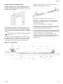
1.Generally,thekeyholemustalwaysbeplacedasclose
aspossibletotheendofarail.However,itmustbe
atleast250mmawayfromtherailend.
2.Iftherailgoesfromwalltowall,itshouldbeplaced
min.400mmfromtherailproleend.
3.Ifatraversesystemismounted,thekeyholeshould
beplacedascloseaspossibleacrosstheendofthe
rail.However,itmustbeatleast250mmawayfrom
therailend.
Ifthetraverserailcontinuesallthewayouttothe
walls,itshouldbeplacedmin.400mmfromtheend
oftherail.
3.2CeilingMountingSystem
3.2.1ConcreteCeiling
Whenreferringtomountinginconcreteceilings,we
differentiatebetweenmassiveconcrete(factorymoulded
concreteelements,prestressedconcretesurfaces,armored
concrete)andhollowsurfaces.
MountingwithQuickCeilingBracket
Whenusingquickceilingttings,allceilingttingsareto
bemountedintheceiling.Thentherailmaybemounted
inthese.Atleast3ceilingttingsshallbeusedperrail.
Theremustsubsequentlybemax.700mmbetweeneach
tting.Theremustbemax.200mmfromtheendofthe
railtothersttting.
Measureuptoallttingsatthesametime.Itisimportant
thatthedrilledholesareonastraightline.Theprecise
markingfortheholesistobecarriedoutusinglaser
technique,chalkline,etc.
Mountinginmassiveconcreteandhollowsurfaces:
14
1586749-C

Installation
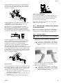
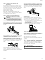
1.Drillholeswitha15mmhammerdrilltoadepthof
54mm.Blowholesclean.
2.InsertM12strokeanchorsintothehole(e.g.Hilti
HKD-SM12orequal).
Whenusingasettingtool(e.g.HiltiHSD-GM12x50
orequal),theanchorwillbecorrectlyfastenedinthe
concrete.
3.Mountthequickttingbyscrewingthepre-mounted
threadedrodinthestrokeanchor.
Itisimportantthatanadhesiveisusedonatting
andnutwhenthethreadedrodismountedtotting.
Inordertoensuretheachievementofmax.
strength,thethreadedrodshouldbescrewedmin.
14mmintotheanchor.
Whenusingastrokeanchorincombination
withthequickbracket,optimumaccuracyisa
requirement.Asanalternative,twocomponent
adhesivemortarforconcretecanberecommended.
Whenallttingsaremounted,pushthehoisttrolley
intotherail.Thehoisttrolleymayfacebothways.If
thetraversetrolleyistobemountedintotherail,itis
importantthatthisfacescorrectlyinconnectiontothe
followingmountingofthetraverserail.
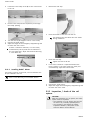
Theendstopismountedinbothendsoftherail.Theend
stopispushedintotherailwiththerubberplugrst,and
fastenedinitiallylooselywithyourngers.
Liftuptherail,adjustthelengthofitandfastenitinto
allceilingttings.
Placetheadjustableendstopscorrectlyandtighten
appropriately.Itisimportantthattheendstopisplaced
sothatthehoistdoesnothitthewall.
Forparallelrailsinatraversesystem,itisimportantthat
theendstopisplacedsothatthetraversetrolleyshitthe
endstopatthesametime.
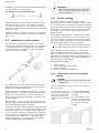
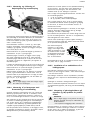
MountingwithStandardCeilingBracket
Theceilingbracketsarepushedontotherailand
distributedwithmax.2mbetweeneachbracketand200
mmfromthelastbracketattheendoftherail.Useat
leastthreebracketsperrail.Itisrecommendedtousean
unevennumberofbrackets,ifonlyonepersonisinstalling
therail.Thus,onebracketisplacedonthecentercreating
balancewhentherailishungintherstbolt.
Inatleastoneendoftherail,useabracketwith
lockingscrewtobesecuredtotherail.
1.Measurefortheholefortheoneexpansionboltof
thecenterbracket.
Drilltheholetoadepthofapprox.80mmwithan
8mm.impactdrillbit.Theholeisdeeperthanthe
expansionboltlengthtofacilitatedismountinglater
on.Fordismounting,youcanthendrivetheboltfully
ininsteadofpullingitout.
2.DriveanexpansionboltM8x75(e.g.HiltiHSAor
equal)in,leavingsufcientroomforthebracket
thickness(6mm),thelockingwasher(2mm)andthe
nut(7mm)plusalittleallowance.Whenyouhave
driveninthebolt,removethenutandthewasher.
3.Insertthehoisttrolleyintherail.Thetrolleycanbe
orientedinbothdirections.
4.Ifyouareinstallingthetraversetrolley,makesurethat
itiscorrectlyorientedforthesubsequentinstallation
ofthetraverserail.
5.Installendstopsatbothendsoftherail.Insertthe
adjustableendstopsintherailwiththerubberplug
siderstandthesteelplatetowardstothebottomof
therail.Fingertightenthescrews.
6.Lifttherailinplace,mountthewashersandnutsand
tightenthemlightly.Adjusttheraillengthwiseand
anglewise,andtightenthenut.
7.Drilltheholeforthebracketintheoneendofthe
railbutontheoppositesideoftherail.Drivein
theexpansionbolt,makethenaladjustmentsand
tighten.
Next,drilltheremainingholesatoneendofthe
bracketslot.Ifthedrillbithitsareinforcementbar
beforetheholeis(50mm)deep,simplydrillatthe
otherendoftheslot.Ifthedrillhitsthereinforcement
barsagain,movethebracketapprox.20-25mmalong
therail.Thebracketwillthencoverthefailedholes.
Iftheholedepthisbetween50-70mm,use
anextensionboltM8x57.
8.Driveintheremainingexpansionbolts,placethe
washersandnutsandtighten.
9.Positiontheadjustablerailstopscorrectlyandtighten.
Makesuretopositiontheendstopssothatthehoist
doesnothitthewall.
Wheninstallingparallelrailinatraversesystem,be
suretopositiontheendstopsattheexactsame
pointstoensurethatthetraversetrolleyhittheend
stopssimultaneously.
3.2.2ConcreteCeilingwithSuspendedCeiling
Forroomswithsuspendedceilingswhicharedifcultto
dismount,itisrecommendedtochooseasolutionwith
wall-mountedorwallsupportmountedrails.
Ifthefalseceilingcanbeeasilyremovedorincaseofa
newmountingofaxedsuspendedceiling,werecommend
aninstallationwithloweringbracketsforaestheticreasons.
Forthissolution,usethelowestrailproleS.
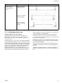
MountingwithPendlingBrackets
Inthecaseofceilingmounting,itmayoftenbenecessary
topendletheraildownward.Thisneedmayariseinthe
evenofmountinginaroomwithasuspendedceiling,
whereyouhavetopendlebetweentheoriginalceilingand
thesuspendedceiling,oriftheceilingissohighthatyou
havetopendletheraildowninordertoensurethatthe
hoist’sliftingintervalsareusedaswellaspossible.
Therearemorepossibilitieswhencarryingoutamounting
withpendles:
1586749-C15

Invacare®EC-Track®
A–Pendlingusingthreadedrodsandroundspacerpipes,
cuton-siteattheinstallationplace.Mountingbyusingthis
methodisdescribedindetailinthissection.
B–Mountingusingadjustablependles.Thispendle
consistsofanupperandlowerpart.Bypushingtheupper
partontotheoutsideofthelowerpart,theadjustable
pendlemaycoveragiveninterval.Asstandard,apendle
canbesuppliedwiththefollowingintervals:
•200–300mm
•280–460mm
•440–740mm
Whenthecorrectpendlespacinghasbeendeterminedin
connectionwiththeassembly,thependleispulledout
tothislength,andfastenedwithascrew.Thenaholeis
drilledallthewaythroughtoanM8x65bolttolockthe
pendleinthedesiredlength.
Theupperpartofthependleshouldbemountedinthe
ceilingasdescribedinchapters3.2.1ConcreteCeiling,
page14
and3.2.3WoodenCeiling,page17aswhen
mountingwithstandardbracket.
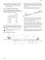
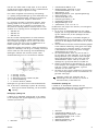
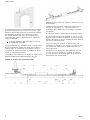
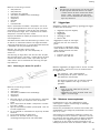
Thelowerpartofthependleshouldbeattachedtothe
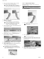
nalstandardceilingtting,asshowninthesketchbelow:
•1.Pendle,upperpart
•2.Pendleunderpart
•3.Spacerpipethroughloweredceiling,Ø15
•4.Standardceilingbracket
•5.Throughlockingbolt,M8x65
Thependlemayalsobesuppliedwithpredetermined
dimensions,avoidingadjustmenton-site.
Rememberalsotoorderceilingbracketswhen
orderingpendle.
RemovableSuspendedCeiling
Incaseofaremovablesuspendedceiling,thespaceabove
thesuspendedceilingisaccessibleandpendlebrackets
andrailcanbeinstalledatthesametime.
•Concreteceiling.
•ExpansionboltsM8x75,2pcs.
•Yoke(Steelplateforeveninstallationsurface),1pcs.
3mm.
•M8nuts,4pcs.
•M8couplingnuts,2pcs.(Collectingsleeve).
•M8lockednuts,2pcs.
•AluminiumpipesØ40,2pcs.
•Ceilingbracket(standard),1pcs.
•Removablesuspendedceiling.
•M8threadedrods,2pcs.
•Lockingwashers,2pcs.11x35x2.
(AnHKDanchorcanbeusedasanalternative,whichthe
rodsarexeddirectlyinto).
1.Togettherightlengthofthependlingbrackets,use
thedistancebetweentheconcreteceilingandthe
lowerfaceofthesuspendedceilingasyourstarting
point.
Thisdistanceisusedtodeterminethelengthofthe
pendlebracketpipeandthethreadedrod.Their
lengthmustequalthepreviouslymeasureddistance
describedabove.
2.Wheninstalling,rstinstalltheyokeforthecenter
ceilingbracket.Todothis,followtheinstructions
fortheinstallationdirectlyinaconcreteceiling.In
thiscase,however,theholesaredrilledforboth
expansionsboltsatthesametime.
3.Whendrivingintheexpansionbolts,leaveapprox.
15mmprotrudingbelowthenut,sothatyoucan
screwthecouplingnutontoittohalfitslength.
Counter-tightenthecouplingnutagainsttheexpansion
boltnut.Measurefortheholeinasuspendedceiling
anddrill/cutthisholetoØ40mm.
4.AttachanM8nutontothethreadedrod(approx.20
mmontotherod)andscrewtherodintothecoupling
nutuntilithitstheexpansionboltandcounter-tighten
thenut.
5.Aftercompletion,pushthetwoaluminiumpipesinto
theholesandfastentherailasdescribedintheusual
instructioninstructions.
Thedistancebetweenthesuspendedceilingand
theceilingbracketmustbemin.1-5mmto
preventdamagestothefalseceiling.
FixedSuspendedCeiling
Incaseofaxedsuspendedceiling,therailinstallationis
carriedoutintwosteps.Theloweringbrackettherefore
needstobesecuredwithoutthesupportfromtheceiling
bracket.
•Concreteceiling.
•ExpansionboltsM8x75,2pcs.
•Yokes,(Steelplateforeveninstallationsurface),2
pcs.3mm.
•M8nuts,6pcs.
•M8couplingnuts,2pcs.
•M8lockingnuts,2pcs.
•AluminiumpipesØ40,2pcs.
•DistancepipesØ20(ornutsandwashers),2pcs.
•Ceilingbracket(standard),1pcs.
•Suspendedceiling.
161586749-C

Installation
•M8threadedrods,2pcs.
•Lockingwashers,2pcs.
(AHKDanchorcanbeusedasanalternative,whichthe
rodsarexeddirectlyinto).
1.Cutthependlebracketpipetoalengthequallingthe
distancemeasuredbetweentheconcreteceilingand
thelowerfaceofthesuspendedceilingminus50mm.
Thislengthisappropriateforadoublegypsumlayerin
theceilingandanextraallowanceof12mm.
2.Cutthethreadedrodtoalengthequallingthedistance
betweentheconcreteceilingandthelowerfaceof
thesuspendedceilingminus10mm.
3.Wheninstalling,rstinstallthetopyokeforthecenter
bracketoftherailInstalltheyokeasdescribedin
theinstallationinstructionsfordirectinstallationina
concreteceiling.Inthiscase,however,drillbothholes
fortheexpansionboltsatthesametime.
4.Whendrivingintheexpansionbolts,leaveapprox.
15mmtoprotrudingbelowthenut,sothatyou
canscrewthecouplingnutontoittoitshalflength.
Counter-tightenthecouplingnutagainsttheexpansion
boltnut.
5.Attachanutapprox.20mmontothethreadedrod
andscrewthethreadedrodintothecouplingnut,until
ittouchestheexpansionbolt,andcounter-tighten
thenut.
6.Attachthebottomyokeandsecureitwithnuts.
Avoidpaintonthebottomsectionofthe
threadedrodsuntiltheinstallationiscomplete.
7.Preparetherestoftheinstallationpointsaftera
carefulandaccuratemeasuring.
Firststepoftheinstallationisnowcompleteand
theconstructionofthesuspendedceilingcanbe
completed.
Inthenalinstallation,positionthedistancepipeinthe
suspendedceiling.Thispipewillprotectthesuspended
ceiling.Cutthedistancepipetoalengthcreatinga
distanceof1-5mmbetweenthelowerfaceofthe
suspendedceilingandtheupperfaceoftheinstallation
bracket;insteadofpipes,nutsandwasherscanbeused
toensuretherecommendeddistance.
3.2.3WoodenCeiling
CAUTION!
–Donotinstallrailstoawoodenceilingwith
tensionscrews,suchascoachscrews.
–Donotinstallrailstoawoodenceilingwith
plainwoodscrews,withouthavingperformed
ariskassessment.
QuickBracket
Insomecases,mountingtoaceilingtimberworkmaybe
analternativetomountingtowallorwallsupport.
Itisprovidedthattheceilingtimberworkisaccessible
fromabove.Whenbeingmountedintheceilingtimber
work,exchangeshouldbeplacedasreinforcement.When
reinforcing,itisimportanttoselectexchangewoodthat
isdimensionedtotoleratethedistancebetweentwo
ceilingbeams,sosufcientcarryingcapacityisachieved.
Whenhavingmarkeduptoallceilingbracketsinthe
ceiling,youshouldexaminewhetherthereisfreespace
abovetheceilingmaterial.Whenthisisdone,holeswith
adiameterofØ12.5mmaredrilledthroughtheceiling
material.Theholesmaynowbelocalizedfromabove,
theycanbepreparedfortheexchanges,andyoumay
measurehowlongthethreadedrodsshouldbe.The
exchangeshouldcoveratleasttwoceilingbeamsoneach
sideofthesuspensionpoint.Whenusingexchanges,
two45x95mmexchangesshouldbeplacedparallelto
eachother,atadistanceof14mm,providingapassage
foranM12threadedrod.Fordeterminingthelengthof
thethreadedrod,determinetheceilingbeam’sheight+
lengthofexchangewood+ceilingmaterial+60mmfor
washerandnuts.
Placetheadaptedthreadedrodbetweentheexchange
woodandputinawasherandnutbeforethethreaded
rodisguidedfurtherdownthroughtheceilingandposition
itwithanaluminiumplate,atighteningwasherandnut
overtheexchangewood.Thealuminiumplateisscrewed
intotheexchangewoodfromthetop.Letapproximately
25mmthreadedrodprotrudedownundertheceiling
material.Aquickceilingbracketmaynowbescrewedonto
thethreadedrodbeneaththeceilingmaterial.Theceiling
bracketisfastenedwithanM12lownut.Thethreaded
rodistobescrewedentirelythroughthenut,butmust
protrudefurtherdownthatbelowthetting.
Whenmountingthebracketandnut,itisimportantto
useadhesiveonbracketaswellasnut.Whenallbrackets
aremounted,liftuptherail,adjustthelengthandsecure
it.Beforetherailisfasteneduptotheceiling,whichis
donefromabovetheceiling,itshouldbecheckedthatthe
exchangewoodisrestingonbothceilingbeams.Ifnot,
somethingshouldbeplacedbetween.
Thenutovertheexchangewoodisnowsecuredcarefully
untilthebracketliesevenlywiththeceilingmaterial.Itis
importantnottotightensomuchthattheceilingmaterial
ispulledupbetweentheceilingbeams.Whenthisis
done,asteelplateisplacedinaroundthethreadedrod
belowtheexchangewood,andthenutissecuredupinto
thesteelplate,thuslockingtheposition.
Finally,alocknutissecuredagainstthenutontheupside
oftheexchangewood.Trolleys,endstopandrailend
plugsaremountedasdescribedinsection5.2.1.
StandardBracket
•ThreadedrodsM10,2pcs.
•M10nuts4pcs.
•Yoke1pcs.
•Braces45x90x1500mm,2pcs.
1586749-C
17

Invacare®EC-Track®
•Beamlayer.
•Underroof/ceiling.
•Ceilingbracket,1pcs.
•LockingnutsM10,2pcs.
•Washer,2pcs.11x35x2.
In some cases, installation with passing screws may be an
alternative to wall or wall support installation.
This requires that the roof beam layer can be accessed
from above. This is often the case in one-storied houses.
To reinforce the roof beam layer, exchanges of 45x95 mm
are placed edgeways.
Instead of the expansion bolts, a M10 threaded rod of
appropriate length is used. An installation plate (yoke
rests on top of the braces.
The exchange must rest on the roof beams on both sides
of the suspension. If this is not possible, the exchange
must be secured to prevent them from tilting when loaded.
The minimum number of three mounting points per rail
for concrete ceiling does not apply to wooden ceilings.
Here, the max. free span determines the number of
mounting points.
The rest of the installation process is similar to the process
for concrete ceilings. It is, however, necessary to drill
both holes for the center bracket (the standard bracket at
the same time.
Cut the threaded rods to appropriate length and attach
the washers and M10 nuts locking nuts.
The threaded rods are to be screwed from below and up
through the yoke. The yoke is fastened from above to the
exchanges with nails and screws.
Before the rail is fastened to the ceiling, which is done
from above, you should double-check that the exchange
wood is resting on two ceiling beams. If not, something
should be placed between.
Be careful when tightening the nuts to prevent damage to
the suspended ceiling.
3.3 Wall installation – end hung rail
The following are recommendations only. Alternatively,
expansion bolts with the similar thickness and quality can
be applied. Always follow the recommendations from
your supplier.
For freely suspended installation, the end of the rails
may be attached to the wall with wall brackets or wall
support. Choose wall support, if you are in doubt of
the load bearing capacity of the wall material. When
installing freely suspended rails, the max. rail length must
be observed, depending on the selected rail prole. The
distance between the walls must be max. 2 m for rail
prole S , 4 m for rail prole M an d 8 m for rail prole L.
If you need to mount or dismount a hoist trolley after
installation, the distance from one wall to the rail must
be at least 160 mm. At secondary installation of Robin
Mover, the distance must be minimum 300 mm. If you
need to mount or dismount the traverse trolley after
installation, the distance between the one wall and the rail
must be at least 350 mm. (Minimum distance from rail to
wall must always be 60 mm. If you have a wall-mounted
rail prole S , y ou c annot m ount o r d ismount the trolley
after installation.
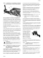
3.3.1RailproleMandL
Wheninstallingwallbracketsorwallsupportlegs,leavea
gapfromtheceilingtotheupperedgeofthewallbracket
oroorsupport.Thegapshouldbeatleast:
•80mmforrailproleM
•150mmforrailproleL
Whenusingwallsupportlegs,cutthesupportlegprole
toanappropriatelengthattheoorend.
Remembertomakeallowancefortheoorsupport
foot.
Incaseofskirtingboards,eitherusethehighwallsupport
foot,orcutawaytheskirtingboard.
Alwaysinstallwallsupportlegsrightatthewallintheir
fulllength.
Markforholesusingalevel,anddrilltheholes.
Concretewall
Whenmountingafreelyhangingrailintoaconcretewall,
awallbracketshouldbeusedformounting.
Formounting,werecommendusingeitherexpansionbolts
M10x68(e.g.HiltiHSAorequal),drillingdepthmin.60
mm,Ø10,oradhesivemortar(e.g.HiltiHIT-HY150and
HASM10orequal),drillingdepthmin.95mm,Ø12(when
mountedinwetrooms,usestainlesssteelHASquality
A4-70).
Brickwall
Whenmountingintobricks,ordinarywallbracketsshould
beused.However,werecommendusingoorsupportsif
thebrickwallisveryporous.
Formountingintomassivebricks,werecommendusing
adhesivemortar(e.g.HiltiHIT-HY50andHASM10or
equal),drillingdepthmin.90mmin½brickand170mm
in1/1brick,Ø12.,(whenmountedinwetrooms,use
stainlesssteelHASqualityA4-70).
Formountinginhollowbricks,werecommendusingeither
aframesheerconnector(e.g.HiltiHRDUGTorequal),
drillingdepthmin.80mm,Ø10,oradhesivemortar(e.g.
HiltiHIT-HY20,andHASM10orequal),drillingdepthmin.
95mm,Ø16.
Formountingintoporousbrickwork,werecommendusing
adhesivemortar(e.g.HiltiHIT-HY50andHASM10or
equal),drillingdepthmin.90mmin½brickand170
181586749-C

Installation
mmin1/1brick,Ø12.Ifwallsupportsareusedwhen
mounting,useHASM8,drillingdepthmin.80mm,Ø10.
Lightweightconcrete
Whenmountinginlightconcrete,youmayeitherusewall
bracketsorwallsupports,dependingontheconditionof
thewall.Formounting,werecommendusingadhesive
mortar(e.g.HiltiHIT-HY50andHASM10orequal),
drillingdepthmin.90mm,Ø12(M8formountingofwall
supports).
Youmayalsousealightconcretesheerconnector(e.g.
HiltiHGN,HUD-110Lorequal),drillingdepthmin.90
mm,Ø10/HUD-18L,drillingdepthmin.80mm,Ø8.
Gypsumwall
Referalsotochapter3.7Wallsupportlegs,page20.
1.Completetheinstallationofthewallbracketorthe
wallsupportlegwithconsole,wallsupportfootand
plugsforcoveringthescrewholes.
2.Insertthehoisttrolleyorthetraversetrolleyintherail.
Thehoisttrolleycanbeorientedinbothdirections,
whereastheorientationofthetraversetrolleymust
correspondtothelayoutofthetraversesystem.
3.Insertendstopsatbothendsoftherailand
nger-tightenthematrst.
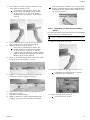
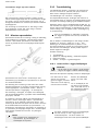
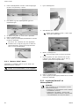
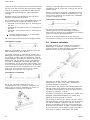
4.Inserttheinsertiontubeintherail.Theholeinthe
tubemustfaceoutwards.
5.Lifttherailwhileholdingontotheinsertiontubeto
preventitfromslidingintotherail.
6.Mounttheinsertiontubeontheconsoleatthewall
bracketorthewallsupportleg.
7.Adjusttheraillengthwisetoachievethecorrect
distancebetweenthewallandtherail.
8.Theremustbeanoverlapofatleast300mmbetween
therailandtheinsertiontube.Checktoverifyby
lookingthroughtheinspectionholeonthesideofthe
rail.Theinspectionholeislocatedexactly300mm
fromtheendoftherail
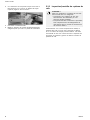
9.Whentherailisproperlypositioned,drillaØ7mm
holethroughtherailandtheinsertiontube,approx.
100mmfromtheendoftherail.Securetherailin
positionwithpassingboltsM6withlockingnuts.
10.Afterpositioningtherail,adjusttheendstoptoits
properposition.Whenpositioningtheendstop,
makesurethatthehoistwillnothitthewall.Witha
traversesystem,ensurethatthetwotraversetrolleys
hittheendstopsimultaneously.
Angular,wall-mounted
Therailcanbemounteddiagonallyintheroom.Therail
mustbeangledmax.45°.
Themountingiscarriedoutasdescribedforordinarywall
mountingwithorwithoutwallsupports.However,the
tubeisdeliveredpreparedforangledmounting.
3.4Wallinstallation–sidehungbracket
orside/endhungbracket
Wheninstallingarailsystemsidehung,theparallelrails
canbeinstalledclosetothewall.
Wheninstallingarailsystemsidehung,thewallmusthave
suchstrength,thatwallsupportlegsareunnecessary.
WheninstallingSprole,2000mmisthemaximum
distancebetweeneachxationpoint,butatleast3points
arenecessary.
WheninstallingMprole,4000mmisthemaximum
distancebetweeneachxationpoint,butatleast3points
arenecessary.
Alwaysmeasurethedistancebetweenbothwalls
accurately,inthecorrectheightandlocationofthesystem.
Thewallbracketcanbeadjusted+/-6mm.Ifmoreis
required,useaplateof6mmbetweenbracketandwall.
Finalappearanceisinuencedbytheparallelism
betweenwallandrail.Beaccurate.
Thetraversesystemmeasurementshere,istheroomsize
measured,deducted206mm(ifbetween-hunginstalled),
and62mm(ifunder-hunginstalled).
Again,thisrequiresanaccuratemeasurementaswell
assomeconsideringoftheadjustabilityduetowall
unevenness.
Wallinstallationdependsonthestructureofthewall.
Alwaysfollowrecommendationsinchapter3.3.1Rail
proleMandL,page18.Afterinstallingthewallbrackets
andthetwoparallelrails,followinstructionsinsection3.8
Mountingtraversesystem,page21
.
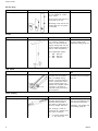
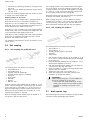
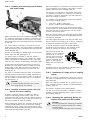
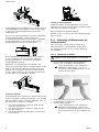
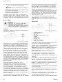
3.5Curves
Followingcurvesareavailable:
•Angle30°0.2+0.2mstraightends
•Angle45°0.2+0.2mstraightends
•Angle60°0.2+0.2mstraightends
•Angle90°0.6+0.6mstraightends
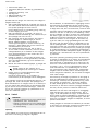
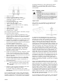
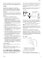
Allcurveshavearadiusof400mm.
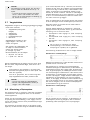
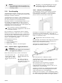
Thecurvesareavailablewithright-handbendsand
left-handbends.Itisespeciallyimportanttodistinguish
betweenrightandleftcurves,whenseveralcurvesare
includedinthesamerailsystem.
RL
1586749-C19

Invacare®EC-Track®
•Leftcurves(L):MountingchannelsAfacingoutfrom
thecurve.
•Rightcurves(R):MountingchannelsAfacinginward
intothecurve.
Pipepinsandcouplingbracketswithlockscrewsareused
tocouplecurveswithstraightrails.
Bracketpositionsonthecurves
Angle30°0.2+0.2mstraightends:Acouplingbracketat
bothends,ifthecurveisconnectedtostraightrails.
Angle45°0.2+0.2mstraightends:Acouplingbracketat
bothends,ifthecurveisconnectedtostraightrailsanda
narrowbracketatthemiddleofthecurve.
Angle60°0.2+0.2mstraightends:Onecouplingbracket,
atbothendsifthecurveisconnectedtostraightrailsand
anarrowbracketatthemiddleofthecurve.
Angle90°0.6+0.6mstraightends:Onecouplingbracket,
ifthecurveisconnectedtostraightrailsandanarrow
bracketatthemiddleofthecurve.
Forinstallationinstructionsforcurves,seesection:5.2.1.1,
section5.2.1.2.
3.6Railcoupling
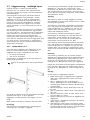
3.6.1RailcouplingforproleMandL
Thefollowingitemsareusedforrailcoupling:
•RailproleMno.1.
•RailproleMno.2.
•Insertiontube(forproleM).
•Couplingbracket(quickorstandard).
•Pipepins.
•Stopscrews.
•BoltM6.
•Washer.
•M6locknuts.
Pushtheinsertiontubehalfwayintorailproleno.1and
secureitwithapassingbolt.Furthermore,drilltheholes
forthepipepinsinrailproleno.2upto3.2mmina
depthcorrespondingtohalfthelengthofthepipepins.
Guidethepipepinshalfwayintorailproleno.1and
squeezethemtogetherintheend.
Pushthecouplingbrackethalfwayontorailproleno.1
andsecureitwiththestopscrew.
Thecouplingbracketisonlyrequiredwhenmountingthe
railontheceiling.Ifyouarecouplingatraverserail,the
couplingbracketisnotrequired.Pushtogetherrailprole
no.2andno.1andsecurethemwiththelockingscrew
inthecouplingbracketandthepassingbolt.
Installthecoupledrailusingtheinstructionsforinstallation
ofstraightrailproles,seesection5.2.
Whencouplinglongrails,itcanbedifculttoliftthe
coupledrailinonepiece.Inthiscase,rstinstalltherst
railontheceiling.Thenliftupthenextrailwhichhas
beenpreparedforcouplingandpushtherailstogether.
3.6.2RailcouplingforproleS
Thefollowingitemsareusedforrailcoupling:
•Railproleno.1
•Railproleno.2
•Couplingbracket(quickorstandard)
•Pipepins
•Stopscrews
1.Drilltheholesforthepipepinsinrailproleno.2up
to3.2mminadepthcorrespondingtohalfthelength
ofthepipepins.
2.Drivethepipepinshalfwayintorailproleno.1and
squeezethemtogetherintheend.
3.Pushthecouplingbrackethalfwayontorailproleno.
1andsecureitwiththestopscrew.
4.Insertrailproleno.2intothecouplingbracketand
drivethetworailstogether.
5.Tightenthestopscrewonrailproleno.2.
6.Installthecoupledrailsusingtheinstructionsfor
installationofstraightrailproles.
IMPORTANT!
Whencouplinglongrails,itcanbedifcultto
liftupthecoupledrailinonepiece.
–Inthiscase,rstinstalltherstrailonthe
ceiling.Thenliftthenextrailwhichhasbeen
preparedforcouplingandpushtherails
together.
3.7Wallsupportlegs
Wallsupportlegsareusedforinstallationongypsumwalls
andwallsofotherlightweightplatematerial.
201586749-C
Sidan laddas...
Sidan laddas...
Sidan laddas...
Sidan laddas...
Sidan laddas...
Sidan laddas...
Sidan laddas...
Sidan laddas...
Sidan laddas...
Sidan laddas...
Sidan laddas...
Sidan laddas...
Sidan laddas...
Sidan laddas...
Sidan laddas...
Sidan laddas...
Sidan laddas...
Sidan laddas...
Sidan laddas...
Sidan laddas...
Sidan laddas...
Sidan laddas...
Sidan laddas...
Sidan laddas...
Sidan laddas...
Sidan laddas...
Sidan laddas...
Sidan laddas...
Sidan laddas...
Sidan laddas...
Sidan laddas...
Sidan laddas...
Sidan laddas...
Sidan laddas...
Sidan laddas...
Sidan laddas...
Sidan laddas...
Sidan laddas...
Sidan laddas...
Sidan laddas...
Sidan laddas...
Sidan laddas...
Sidan laddas...
Sidan laddas...
Sidan laddas...
Sidan laddas...
Sidan laddas...
Sidan laddas...
Sidan laddas...
Sidan laddas...
Sidan laddas...
Sidan laddas...
Sidan laddas...
Sidan laddas...
Sidan laddas...
Sidan laddas...
Sidan laddas...
Sidan laddas...
Sidan laddas...
Sidan laddas...
Sidan laddas...
Sidan laddas...
Sidan laddas...
Sidan laddas...
Sidan laddas...
Sidan laddas...
Sidan laddas...
Sidan laddas...
Sidan laddas...
Sidan laddas...
Sidan laddas...
Sidan laddas...
Sidan laddas...
Sidan laddas...
Sidan laddas...
Sidan laddas...
Sidan laddas...
Sidan laddas...
Sidan laddas...
Sidan laddas...
Sidan laddas...
Sidan laddas...
Sidan laddas...
Sidan laddas...
Sidan laddas...
Sidan laddas...
Sidan laddas...
Sidan laddas...
Sidan laddas...
Sidan laddas...
Sidan laddas...
Sidan laddas...
Sidan laddas...
Sidan laddas...
Sidan laddas...
Sidan laddas...
Sidan laddas...
Sidan laddas...
Sidan laddas...
Sidan laddas...
Sidan laddas...
Sidan laddas...
Sidan laddas...
Sidan laddas...
Sidan laddas...
Sidan laddas...
Sidan laddas...
Sidan laddas...
Sidan laddas...
Sidan laddas...
Sidan laddas...
Sidan laddas...
Sidan laddas...
Sidan laddas...
Sidan laddas...
Sidan laddas...
-
 1
1
-
 2
2
-
 3
3
-
 4
4
-
 5
5
-
 6
6
-
 7
7
-
 8
8
-
 9
9
-
 10
10
-
 11
11
-
 12
12
-
 13
13
-
 14
14
-
 15
15
-
 16
16
-
 17
17
-
 18
18
-
 19
19
-
 20
20
-
 21
21
-
 22
22
-
 23
23
-
 24
24
-
 25
25
-
 26
26
-
 27
27
-
 28
28
-
 29
29
-
 30
30
-
 31
31
-
 32
32
-
 33
33
-
 34
34
-
 35
35
-
 36
36
-
 37
37
-
 38
38
-
 39
39
-
 40
40
-
 41
41
-
 42
42
-
 43
43
-
 44
44
-
 45
45
-
 46
46
-
 47
47
-
 48
48
-
 49
49
-
 50
50
-
 51
51
-
 52
52
-
 53
53
-
 54
54
-
 55
55
-
 56
56
-
 57
57
-
 58
58
-
 59
59
-
 60
60
-
 61
61
-
 62
62
-
 63
63
-
 64
64
-
 65
65
-
 66
66
-
 67
67
-
 68
68
-
 69
69
-
 70
70
-
 71
71
-
 72
72
-
 73
73
-
 74
74
-
 75
75
-
 76
76
-
 77
77
-
 78
78
-
 79
79
-
 80
80
-
 81
81
-
 82
82
-
 83
83
-
 84
84
-
 85
85
-
 86
86
-
 87
87
-
 88
88
-
 89
89
-
 90
90
-
 91
91
-
 92
92
-
 93
93
-
 94
94
-
 95
95
-
 96
96
-
 97
97
-
 98
98
-
 99
99
-
 100
100
-
 101
101
-
 102
102
-
 103
103
-
 104
104
-
 105
105
-
 106
106
-
 107
107
-
 108
108
-
 109
109
-
 110
110
-
 111
111
-
 112
112
-
 113
113
-
 114
114
-
 115
115
-
 116
116
-
 117
117
-
 118
118
-
 119
119
-
 120
120
-
 121
121
-
 122
122
-
 123
123
-
 124
124
-
 125
125
-
 126
126
-
 127
127
-
 128
128
-
 129
129
-
 130
130
-
 131
131
-
 132
132
-
 133
133
-
 134
134
-
 135
135
-
 136
136


Invacare EC-Track Installation & Technical Description
- Typ
- Installation & Technical Description
på andra språk
- français: Invacare EC-Track
- English: Invacare EC-Track
- dansk: Invacare EC-Track
Relaterade papper
Andra dokument
-
FläktGroup EQAZ-05-42 Adjustable plastic feet Installation and Maintenance Manual
-
Yamaha BCS251 Användarmanual
-
DeLOCK 42632 Datablad
-
 Molift Air 350 Användarmanual
-
Arrow Free 5201-95 Installationsguide
-
NEXON PS10 Användarmanual
-
Chamberlain 5580 Bruksanvisning
-
 Molift Air 500 Användarmanual
-
 Lekolar Akuframe Light Ceiling Användarmanual
-
LIVARNO 399127 Bruksanvisning


