AVENTICS Multistage ejector, series EMS Bruksanvisningar
- Typ
- Bruksanvisningar

Betriebsanleitung | Operating instructions | Notice d’instruction |
Istruzioni per l’uso | Instrucciones de servicio | Bruksanvisning
R412026279/2017-08, Replaces: –, DE/EN/FR/IT/ES/SV
Mehrstufenejektor
Multistage ejector
Éjecteur multi-étages
Eiettore multistadio
Eyector multi etapa
Flerstegsejektor
EMS
Deutsch
1 Zu dieser Dokumentation
Diese Anleitung enthält wichtige Informationen, um das
Produkt sicher und sachgerecht zu montieren und in
Betrieb zu nehmen.
O Lesen Sie diese Anleitung vollständig und
insbesondere das Kapitel 2 „Sicherheitshinweise“,
bevor Sie mit dem Produkt arbeiten.
Gültigkeit der Dokumentation
O Diese Dokumentation gilt für Mehrstufenejektoren der
Serie EMS.
Zusätzliche Dokumentationen
O Beachten Sie auch die Anleitungen der übrigen
Anlagenkomponenten.
O Beachten Sie außerdem allgemein gültige, gesetzliche
und sonstige verbindliche Regelungen der
europäischen bzw. nationalen Gesetzgebung sowie die
in Ihrem Land gültigen Vorschriften zur
Unfallverhütung und zum Umweltschutz.
Darstellung von Informationen
Warnhinweise
In
dieser Anleitung stehen Warnhinweise vor einer
Handlungsanweisung, bei der die Gefahr von Personen-
oder Sachschäden besteht. Die beschriebenen Maßnahmen
zur Gefahrenabwehr müssen eingehalten werden.
Aufbau von Warnhinweisen
Bedeutung der Signalwörter
SIGNALWORT
Art und Quelle der Gefahr
Folgen bei Nichtbeachtung der Gefahr
O Maßnahmen zur Abwehr der Gefahr
GEFAHR
Kennzeichnet eine gefährliche Situation, in der Tod oder
schwere Körperverletzung eintreten werden, wenn sie
nicht vermieden wird.
WARNUNG
Kennzeichnet eine gefährliche Situation, in der Tod oder
schwere Körperverletzung eintreten können, wenn sie
nicht vermieden wird.
VORSICHT
Kennzeichnet eine gefährliche Situation, in der leichte
bis mittelschwere Körperverletzungen eintreten
können, wenn sie nicht vermieden wird.
Symbole
2 Sicherheitshinweise
Das Produkt wurde gemäß den allgemein anerkannten
Regeln der Technik hergestellt. Trotzdem besteht die
Gefahr von Personen- und Sachschäden, wenn Sie die
folgenden grundsätzlichen Sicherheitshinweise und die
Warnhinweise vor Handlungsanweisungen in dieser
Anleitung nicht beachten.
O Lesen Sie diese Anleitung gründlich und vollständig,
bevor Sie mit dem Produkt arbeiten.
O Bewahren Sie die Anleitung so auf, dass sie jederzeit
für alle Benutzer zugänglich ist.
O Geben Sie das Produkt an Dritte stets zusammen mit
der Betriebsanleitung weiter.
Bestimmungsgemäße Verwendung
W Der Ejektor dient zur Vakuumerzeugung um in
Verbindung mit Sauggreifern Objekte mittels Vakuum
zu greifen und dann zu transportieren.
W Als zu evakuierendes Medium sind neutrale Gase
gemäß ISO 8573-1 zugelassen. Neutrale Gase sind
Luft, Stickstoff und Edelgase (z. B. Argon, Helium,
Neon). Nicht zugelassen sind aggressive Gase oder
Medien wie z. B. Säuren, Säuredämpfe, Laugen,
Biozide, Desinfektionsmittel und Reinigungsmittel.
W Das Gerät dient nicht zum Transport (Durchsaugen)
von Flüssigkeiten, nicht neutralen Gasen und/oder
Granulaten.
W Schalldämpfer darf nicht verschlossen sein.
W Andernfalls ist Beschädigung des Ejektors und sogar
Verletzungsgefahr nicht auszuschließen.
W Die Ejektoren dürfen nur mit einem maximalen Druck
von 6,0 bar betrieben werden.
W Montage, Inbetriebnahme, Wartung nur durch
Fachkräfte.
W Bedienen durch vom Betreiber unterwiesenes
Bedienpersonal.
W Personen die aufgrund einer physischen, psychischen
oder sensorischen Einschränkung nicht in der Lage
sind die Maschine gefahrlos zu bedienen, dürfen die
Maschine nicht oder nur unter Aufsicht einer
verantwortlichen Person bedienen.
Die bestimmungsgemäße Verwendung schließt auch ein,
dass Sie diese Anleitung und insbesondere das Kapitel 2
„Sicherheitshinweise“
vollständig gelesen und verstanden
haben.
ACHTUNG
Kennzeichnet Sachschäden: Das Produkt oder die
Umgebung können beschädigt werden.
Wenn diese Information nicht beachtet wird, kann
das zu Verschlechterungen im Betriebsablauf
führen.
AVENTICS | EMS | R412026279–BAL–001–AA | Deutsch 1

Typ / Type / Tipo
EMS 125/150
1
675
9 / 10
44 89 / 10
3
1
Typ / Type / Tipo
EMS 25/50
Typ / Type / Tipo
EMS 75/100
1
1
24 / 5
3
2
Nicht bestimmungsgemäße Verwendung
Als nicht bestimmungsgemäße Verwendung gilt, wenn Sie
den Ejektor
O außerhalb der Anwendungsgebiete verwenden, die in
dieser Anleitung genannt werden,
O unter Betriebsbedingungen verwenden, die von den in
dieser Anleitung beschriebenen abweichen,
Qualifikation des Personals
Die Montage, Inbetriebnahme, Demontage und
Instandhaltung (inkl. Wartung und Pflege) erfordern
grundlegende mechanische und pneumatische
Kenntnisse sowie Kenntnisse der zugehörigen
Fachbegriffe.
Um die Betriebssicherheit zu gewährleisten, dürfen diese
Tätigkeiten daher nur von einer entsprechenden Fachkraft
oder einer unterwiesenen Person unter Leitung einer
Fachkraft durchgeführt werden.
Eine Fachkraft ist, wer aufgrund seiner fachlichen
Ausbildung, seiner Kenntnisse und Erfahrungen, sowie
seiner Kenntnisse der einschlägigen Bestimmungen, die
ihm übertragenen Arbeiten beurteilen, mögliche Gefahren
erkennen und geeignete Sicherheitsmaßnahmen treffen
kann. Eine Fachkraft muss die einschlägigen
fachspezifischen Regeln einhalten.
Allgemeine Sicherheitshinweise
W Die Betriebsanleitung enthält wichtige Informationen
zum Umgang mit dem System. Betriebsanleitung
sorgfältig durchlesen und für spätere Zwecke
aufbewahren!
W Der Anschluss und die Inbetriebnahme des Systems
darf erst erfolgen, nachdem die Betriebsanleitung
gelesen und verstanden wurde!
W Arbeiten am System dürfen nur von qualifiziertem
Fachpersonal durchgeführt werden.
W Nur die vorgesehenen Anschlussmöglichkeiten,
Befestigungsbohrungen und Befestigungsmittel
verwenden.
W Wartung nur bei demontiertem Druckluftanschluss
W Allgemeine Sicherheitsvorschriften, EN-Normen und
VDE-Richtlinien müssen beachtet und eingehalten
werden!
W Bei der Handhabung von gefährlichen Stoffen sind die
für diese Stoffe gültigen Sicherheitshinweise zu
beachten.
Produkt- und technologieabhängige
Sicherheitshinweise
W Das Produkt wird in Verbindung mit einem
automatisierten Handlingsystem (Portal/Roboter)
eingesetzt.
W Deshalb gelten außerdem die Sicherheitsvorschriften
des entsprechenden Systems!
W Unter Druckluft stehende Geräte können Personen-
und Sachschäden verursachen.
W Abluft und eventuell angesaugte Medien und Teile
treten mit hoher Geschwindigkeit aus dem
Abluftanschluss aus.
W Verletzungsgefahr – vor allem im Augenbereich! Nicht
in den Luftstrom treten oder schauen.
W Anschlüsse unbedingt richtig anschließen und niemals
verschließen – Berstgefahr!
W Vakuum überwachen, um Störungen der
Vakuumerzeugung zu erkennen.
W Das Produkt darf nicht in aggressiver Umgebungsluft
(z. B. Lösungsmitteldämpfe) betrieben werden!
3Lieferumfang
Im Lieferumfang sind enthalten:
W 1 Mehrstufenejektor gemäß Bestellung
(Typen s. Abb. , Technische Daten)
W Betriebsanleitung
W Befestigungsschrauben
4 Montage und Betrieb
Ejektormodul befestigen
Der Schalldämpfer fixiert das Ejektormodul.
Deshalb darf der Ejektor nicht ohne Schalldämpfer
betrieben werden.
Ausnahme: Wenn der Ejektor ohne Schalldämpfer
betrieben werden soll, muss das Ejektormodul über die
Schalldämpfer-Aufnahme und die beiden mitgelieferten
Schrauben M4x16 (2 Nm) gesichert werden (vgl. Abschnitt
„Aufbau“ ).
WARNUNG
Ejektormodul kann aus der Bohrung geschleudert
werden, wenn es unzureichend fixiert ist
Schwerer Personenschaden
O Ejektormodul fixieren
O Schutzbrille tragen
VORSICHT
Verletzungsgefahr durch Montage unter Druck oder
Spannung!
Die Montage unter Druck oder anliegender elektrischer
Spannung kann zu Verletzungen führen und das
Produkt oder Anlagenteile beschädigen.
O Schalten Sie den relevanten Anlagenteil drucklos
und spannungsfrei, bevor Sie das Produkt
montieren.
O Sichern Sie die Anlage gegen Wiedereinschalten.
1
3
1
AVENTICS | EMS | R412026279–BAL–001–AA | Deutsch 2
Aufbau
Pos Bezeichnung
1 Druckluftanschluss, max. 15 Nm
2 Vakuumanschluss, max. 25 Nm
3 Abluftöffnungen
4 Abblasanschluss/Belüftungsanschluss, max.15 Nm
Externes Abblasen mit Abblasventil 2/2-NC* (vakuumdicht)
5 Vakuumabfrage, max. 10 Nm
6 Befestigungsschrauben M5 (4x), max. 5 Nm
7 Schalldämpfer-Aufnahme
8 Befestigungsschrauben M4 (8x für Gehäusedeckel) max. 2,5 Nm
9 Befestigungsschrauben M4x16 (2x für Schalldämpferaufnahme) max. 2 Nm
10 Befestigungsschrauben M4x35 (2x für Schalldämpfer) max. 2 Nm
* Weiteres Zubehör entnehmen Sie bitte dem Online-Katalog unter www.aventics.com/pneumatics-catalog
Pneumatischer Anschluss
Pos Bezeichnung
1 Druckluftanschluss
2 Vakuumanschluss
3 Abluft
4 Abblasen/Belüftung
5 Vakuumabfrage

L5
L4
B4
B3
B2
B1
LG5
G2
G3
G4
B
L2
L
X1L2
L1
L3
H1
H
G1
Y1
3
O Befestigen Sie den Ejektor mit den mitgelieferten M5-
Schrauben (4x). Anzugsmoment max. 5 Nm!
Alternativ kann ein Befestigungswinkel verwendet
werden, vgl. Kapitel 6 „Zubehör“.
Anschluss
W Verwenden Sie die empfohlenen
Schlauchdurchmesser.
W Ein zu klein gewählter Innendurchmesser
druckluftseitig bewirkt, dass dem Gerät nicht
genügend Druckluft für die optimale Leistung
zugeführt wird.
W Ein zu klein gewählter Innendurchmesser
vakuumseitig bewirkt einen zu hohen
Strömungswiderstand entlang der Schlauchwandung,
was sich negativ auf die Saugleistung und damit auf
die Ansaugzeiten auswirkt. Allerdings sollten die
Schlauchdurchmesser nicht beliebig groß gewählt
werden um bedingt durch das vergrößerte Volumen,
die Ansaugzeiten nicht zu verlängern.
W Schlauchleitungen sollten möglichst kurz verlegt
werden, um die Reaktionszeiten möglichst klein zu
halten. Schlauchleitungen knick- und quetschfrei
verlegen.
Nach dem Herstellen aller pneumatischen Verbindungen
kann das Gerät mit Druckluft beaufschlagt werden.
VORSICHT
Betrieb ohne Schalldämpfer
Ejektor emittiert Schall
O Gehörschutz tragen
VORSICHT
Angesaugte Partikel mit hoher Geschwindigkeit
Augenschäden
O Schutzbrille tragen
VORSICHT
Durch Druckluft/Vakuum können geschlossene Geräte
explodieren/implodieren
Personen- und/oder Sachschäden
O Schutzbrille tragen
O Schalldämpfer darf nicht verschlossen sein
2
Weitere Angaben
Für sichere Installation und störungsfreien Betrieb sind
weiterhin folgende Verhaltensweisen nebeneinander zu
beachten und einzuhalten:
W Prüfen Sie das Produkt auf offensichtliche Mängel, wie
beispielsweise Risse im Gehäuse oder fehlende
Schrauben, Abdeckkappen, Dichtungen!
W Elektrische Leitungsverbindungen, Pneumatik- und
Vakuumschläuche müssen dauerhaft mit dem Produkt
verbunden und gesichert sein!
W Produkt spannungs- und druckfrei schalten und gegen
unbefugtes Wiedereinschalten sichern!
W Der Betrieb in explosionsgefährdeter Umgebung ist
nicht zulässig. Brand- und Explosionsgefahr!
W Eigenmächtige Umbauten und Veränderungen des
Produktes und seinen Bauteilen sind aus
Sicherheitsgründen verboten!
Ausnahme: Ein Upgrade des Ejektors auf eine höhere
Leistungsklasse ist mithilfe eines Upgrade-Sets auf
Anfrage möglich.
W Im Betrieb ausreichend Sicherheitsabstand einhalten,
Quetschgefahr durch sich bewegende Teile!
W Das Produkt ist mit geeigneten Schutzvorrichtungen
zu betreiben. Vor unbefugtem Zutritt absichern!
W Der Betrieb außerhalb der spezifizierten
Leistungsgrenzen ist nicht zulässig.
5 Instandhaltung und
Instandsetzung
Wartung
Der Ejektor kann zu Wartungs- und Reinigungszwecken
geöffnet werden. Bei erneutem Zusammenbau sind die
vorgegebenen Anzugsmomente der Schrauben
einzuhalten (vgl. Abschnitt „Aufbau“ ).
Ersatz- und Verschleißteile
Bei fehlerhafter Montage, Betrieb außerhalb der
Leistungsgrenzen und eigenmächtigen Umbauten
bzw. Veränderungen des Produkts erlischt die
Gewährleistung!
Die Einbaulage des Ejektors ist beliebig.
Bezeichnung Materialnummer
Schalldämpfer R412026280
Dichtrahmen R412026281
O-Ring R412026282
1
AVENTICS | EMS | R412026279–BAL–001–AA | Deutsch 3
Abmessungen und Anschlüsse
Typ L L1 L2 L3 L4 L5 B B1 B2 B3 B4 H H1 X1 Y1
EMS-25-HF/HV
EMS-50-HF/HV
168285546711364515316 – –72747462
EMS-75-HF/HV
EMS 100-HF/HV
168 285 54 67 113 64 83 85 16 48 – 72 74 74 62
EMS-125-HF/HV
EMS-150-HF/HV
168 285 54 67 113 64 115 117 16 48 80 72 74 74 62
Typ G1 G2 G3 G4 G5 Lg5 empf. Schlauchinnen - Ø*
Druckluft Vakuum
EMS-25-HF/HV G3/8"-IG G3/4"-IG G1/4"-IG G1/8"-IG M5-AG 8,5 6 20
EMS-50-HF/HV G3/8"-IG G3/4"-IG G1/4"-IG G1/8"-IG M5-AG 8,5 6 25
EMS-75-HF/HV
EMS-100-HF/HV
G3/8"-IG G1"-IG G1/4"-IG G1/8"-IG M5-AG 8,5 9 32
EMS-125-HF/HV
EMS-150-HF/HV
G3/8"-IG G1"-IG G1/4"-IG G1/8"-IG M5-AG 8,5 11 32
* Bei Schlauchlängen bis 2 m

Verwendete Materialien
Typ Schallpegel Druck-
bereich
Gewicht
frei
[dB]
angesaugt
[dB]
[bar] [kg]
EMS-25-HF 61 54 2,0 … 6,0 0,8
EMS-25-HV 65 55 2,0 … 6,0 0,8
EMS-50-HF 65 55 2,0 … 6,0 0,8
EMS-50-HV 66 59 2,0 … 6,0 0,8
EMS-75-HF 67 57 2,0 … 6,0 1,1
EMS-75-HV 68 62 2,0 … 6,0 1,1
EMS-100-HF 69 58 2,0 … 6,0 1,1
EMS-100-HV 70 64 2,0 … 6,0 1,1
EMS-125-HF 70 60 2,0 … 6,0 1,5
EMS-125-HV 72 65 2,0 … 6,0 1,5
EMS-150-HF 71 61 2,0 … 6,0 1,5
EMS-150-HV 73 66 2,0 … 6,0 1,5
Bauteil Material
Grundkörper und
Anschlussplatte
Glasfaserverstärkter
Kunststoff
Deckel Glasfaserverstärkter
Kunststoff
Innenteile Aluminiumlegierung,
Messing, NBR
Dichtungen NBR
Schrauben Stahl verzinkt; Edelstahl
Befestigungsblech Stahl verzinkt
AVENTICS | EMS | R412026279–BAL–001–AA | Deutsch 4
L5
L4
B4
B3
B2
B1
LG5
G2
G3
G4
B
L2
L
X1L2
L1
L3
H1
H
G1
Y1
3
6Zubehör
Weiteres Zubehör entnehmen Sie bitte dem Online-Katalog unter
www.aventics.com/pneumatics-catalog
7Technische Daten
Bezeichnung Typ Materialnummer
Verschlussstopfen R412026139
Befestigungswinkel (inkl.
Schrauben)
R412026103
Düsenpatrone SEP-HF R412026137
SEP-HV R412026138
Max. Vakuum [%] Typ HF = 60
Typ HV = 90
Opt. Betriebsdruck [bar] 4 ... 5
Betriebsdruck
[bar] 2 ... 6
Einbaulage beliebig
Temperaturbereich [°C] 0...+60
Betriebsmedium
druckluftseitig
N
eutrale Gase gemäß EN 983
z. B. Luft, Stickstoff und
Edelgase (z. B. Argon, Helium,
Neon), gefiltert 40 μm, geölt
oder ungeölt,
Druckluftqualität Klasse 3-3-3
nach ISO 8573-1
Betriebsmedium
vakuumseitig
trockene und nicht
aggressive Gase
Typ Evakuie-
rungsgrad
Max. Saugver-
mögen
Luftver-
brauch
1)
1)
Bei optimalem Betriebsdruck
[%] [l/min] [l/min]
EMS-25-HF 60 290 80
EMS-25-HV 90 300 105
EMS-50-HF 60 500 160
EMS-50-HV 90 510 210
EMS-75-HF 60 710 230
EMS-75-HV 90 720 305
EMS-100-HF 60 860 300
EMS-100-HV 90 870 395
EMS-125-HF 60 1010 370
EMS-125-HV 90 1010 470
EMS-150-HF 60 1120 435
EMS-150-HV 90 1140 545
O Befestigen Sie den Ejektor mit den mitgelieferten M5-
Schrauben (4x). Anzugsmoment max. 5 Nm!
Alternativ kann ein Befestigungswinkel verwendet
werden, vgl. Kapitel 6 „Zubehör“.
Anschluss
W Verwenden Sie die empfohlenen
Schlauchdurchmesser.
W Ein zu klein gewählter Innendurchmesser
druckluftseitig bewirkt, dass dem Gerät nicht
genügend Druckluft für die optimale Leistung
zugeführt wird.
W Ein zu klein gewählter Innendurchmesser
vakuumseitig bewirkt einen zu hohen
Strömungswiderstand entlang der Schlauchwandung,
was sich negativ auf die Saugleistung und damit auf
die Ansaugzeiten auswirkt. Allerdings sollten die
Schlauchdurchmesser nicht beliebig groß gewählt
werden um bedingt durch das vergrößerte Volumen,
die Ansaugzeiten nicht zu verlängern.
W Schlauchleitungen sollten möglichst kurz verlegt
werden, um die Reaktionszeiten möglichst klein zu
halten. Schlauchleitungen knick- und quetschfrei
verlegen.
Nach dem Herstellen aller pneumatischen Verbindungen
kann das Gerät mit Druckluft beaufschlagt werden.
VORSICHT
Betrieb ohne Schalldämpfer
Ejektor emittiert Schall
O Gehörschutz tragen
VORSICHT
Angesaugte Partikel mit hoher Geschwindigkeit
Augenschäden
O Schutzbrille tragen
VORSICHT
Durch Druckluft/Vakuum können geschlossene Geräte
explodieren/implodieren
Personen- und/oder Sachschäden
O Schutzbrille tragen
O Schalldämpfer darf nicht verschlossen sein
2
Weitere Angaben
Für sichere Installation und störungsfreien Betrieb sind
weiterhin folgende Verhaltensweisen nebeneinander zu
beachten und einzuhalten:
W Prüfen Sie das Produkt auf offensichtliche Mängel, wie
beispielsweise Risse im Gehäuse oder fehlende
Schrauben, Abdeckkappen, Dichtungen!
W Elektrische Leitungsverbindungen, Pneumatik- und
Vakuumschläuche müssen dauerhaft mit dem Produkt
verbunden und gesichert sein!
W Produkt spannungs- und druckfrei schalten und gegen
unbefugtes Wiedereinschalten sichern!
W Der Betrieb in explosionsgefährdeter Umgebung ist
nicht zulässig. Brand- und Explosionsgefahr!
W Eigenmächtige Umbauten und Veränderungen des
Produktes und seinen Bauteilen sind aus
Sicherheitsgründen verboten!
Ausnahme: Ein Upgrade des Ejektors auf eine höhere
Leistungsklasse ist mithilfe eines Upgrade-Sets auf
Anfrage möglich.
W Im Betrieb ausreichend Sicherheitsabstand einhalten,
Quetschgefahr durch sich bewegende Teile!
W Das Produkt ist mit geeigneten Schutzvorrichtungen
zu betreiben. Vor unbefugtem Zutritt absichern!
W Der Betrieb außerhalb der spezifizierten
Leistungsgrenzen ist nicht zulässig.
5 Instandhaltung und
Instandsetzung
Wartung
Der Ejektor kann zu Wartungs- und Reinigungszwecken
geöffnet werden. Bei erneutem Zusammenbau sind die
vorgegebenen Anzugsmomente der Schrauben
einzuhalten (vgl. Abschnitt „Aufbau“ ).
Ersatz- und Verschleißteile
Bei fehlerhafter Montage, Betrieb außerhalb der
Leistungsgrenzen und eigenmächtigen Umbauten
bzw. Veränderungen des Produkts erlischt die
Gewährleistung!
Die Einbaulage des Ejektors ist beliebig.
Bezeichnung Materialnummer
Schalldämpfer R412026280
Dichtrahmen R412026281
O-Ring R412026282
1
AVENTICS | EMS | R412026279–BAL–001–AA | Deutsch 3
AVENTICS | EMS | R412026279–BAL–001–AA | Deutsch 5
Abmessungen und Anschlüsse
Typ L L1 L2 L3 L4 L5 B B1 B2 B3 B4 H H1 X1 Y1
EMS-25-HF/HV
EMS-50-HF/HV
168285546711364515316 – –72747462
EMS-75-HF/HV
EMS 100-HF/HV
168 285 54 67 113 64 83 85 16 48 – 72 74 74 62
EMS-125-HF/HV
EMS-150-HF/HV
168 285 54 67 113 64 115 117 16 48 80 72 74 74 62
Typ G1 G2 G3 G4 G5 Lg5 empf. Schlauchinnen - Ø*
Druckluft Vakuum
EMS-25-HF/HV G3/8"-IG G3/4"-IG G1/4"-IG G1/8"-IG M5-AG 8,5 6 20
EMS-50-HF/HV G3/8"-IG G3/4"-IG G1/4"-IG G1/8"-IG M5-AG 8,5 6 25
EMS-75-HF/HV
EMS-100-HF/HV
G3/8"-IG G1"-IG G1/4"-IG G1/8"-IG M5-AG 8,5 9 32
EMS-125-HF/HV
EMS-150-HF/HV
G3/8"-IG G1"-IG G1/4"-IG G1/8"-IG M5-AG 8,5 11 32
* Bei Schlauchlängen bis 2 m

Typ / Type / Tipo
EMS 125/150
1
675
9 / 10
44 89 / 10
3
1
Typ / Type / Tipo
EMS 25/50
Typ / Type / Tipo
EMS 75/100
1
1
24 / 5
3
2
Nicht bestimmungsgemäße Verwendung
Als nicht bestimmungsgemäße Verwendung gilt, wenn Sie
den Ejektor
O außerhalb der Anwendungsgebiete verwenden, die in
dieser Anleitung genannt werden,
O unter Betriebsbedingungen verwenden, die von den in
dieser Anleitung beschriebenen abweichen,
Qualifikation des Personals
Die Montage, Inbetriebnahme, Demontage und
Instandhaltung (inkl. Wartung und Pflege) erfordern
grundlegende mechanische und pneumatische
Kenntnisse sowie Kenntnisse der zugehörigen
Fachbegriffe.
Um die Betriebssicherheit zu gewährleisten, dürfen diese
Tätigkeiten daher nur von einer entsprechenden Fachkraft
oder einer unterwiesenen Person unter Leitung einer
Fachkraft durchgeführt werden.
Eine Fachkraft ist, wer aufgrund seiner fachlichen
Ausbildung, seiner Kenntnisse und Erfahrungen, sowie
seiner Kenntnisse der einschlägigen Bestimmungen, die
ihm übertragenen Arbeiten beurteilen, mögliche Gefahren
erkennen und geeignete Sicherheitsmaßnahmen treffen
kann. Eine Fachkraft muss die einschlägigen
fachspezifischen Regeln einhalten.
Allgemeine Sicherheitshinweise
W Die Betriebsanleitung enthält wichtige Informationen
zum Umgang mit dem System. Betriebsanleitung
sorgfältig durchlesen und für spätere Zwecke
aufbewahren!
W Der Anschluss und die Inbetriebnahme des Systems
darf erst erfolgen, nachdem die Betriebsanleitung
gelesen und verstanden wurde!
W Arbeiten am System dürfen nur von qualifiziertem
Fachpersonal durchgeführt werden.
W Nur die vorgesehenen Anschlussmöglichkeiten,
Befestigungsbohrungen und Befestigungsmittel
verwenden.
W Wartung nur bei demontiertem Druckluftanschluss
W Allgemeine Sicherheitsvorschriften, EN-Normen und
VDE-Richtlinien müssen beachtet und eingehalten
werden!
W Bei der Handhabung von gefährlichen Stoffen sind die
für diese Stoffe gültigen Sicherheitshinweise zu
beachten.
Produkt- und technologieabhängige
Sicherheitshinweise
W Das Produkt wird in Verbindung mit einem
automatisierten Handlingsystem (Portal/Roboter)
eingesetzt.
W Deshalb gelten außerdem die Sicherheitsvorschriften
des entsprechenden Systems!
W Unter Druckluft stehende Geräte können Personen-
und Sachschäden verursachen.
W Abluft und eventuell angesaugte Medien und Teile
treten mit hoher Geschwindigkeit aus dem
Abluftanschluss aus.
W Verletzungsgefahr – vor allem im Augenbereich! Nicht
in den Luftstrom treten oder schauen.
W Anschlüsse unbedingt richtig anschließen und niemals
verschließen – Berstgefahr!
W Vakuum überwachen, um Störungen der
Vakuumerzeugung zu erkennen.
W Das Produkt darf nicht in aggressiver Umgebungsluft
(z. B. Lösungsmitteldämpfe) betrieben werden!
3Lieferumfang
Im Lieferumfang sind enthalten:
W 1 Mehrstufenejektor gemäß Bestellung
(Typen s. Abb. , Technische Daten)
W Betriebsanleitung
W Befestigungsschrauben
4 Montage und Betrieb
Ejektormodul befestigen
Der Schalldämpfer fixiert das Ejektormodul.
Deshalb darf der Ejektor nicht ohne Schalldämpfer
betrieben werden.
Ausnahme: Wenn der Ejektor ohne Schalldämpfer
betrieben werden soll, muss das Ejektormodul über die
Schalldämpfer-Aufnahme und die beiden mitgelieferten
Schrauben M4x16 (2 Nm) gesichert werden (vgl. Abschnitt
„Aufbau“ ).
WARNUNG
Ejektormodul kann aus der Bohrung geschleudert
werden, wenn es unzureichend fixiert ist
Schwerer Personenschaden
O Ejektormodul fixieren
O Schutzbrille tragen
VORSICHT
Verletzungsgefahr durch Montage unter Druck oder
Spannung!
Die Montage unter Druck oder anliegender elektrischer
Spannung kann zu Verletzungen führen und das
Produkt oder Anlagenteile beschädigen.
O Schalten Sie den relevanten Anlagenteil drucklos
und spannungsfrei, bevor Sie das Produkt
montieren.
O Sichern Sie die Anlage gegen Wiedereinschalten.
1
3
1
AVENTICS | EMS | R412026279–BAL–001–AA | Deutsch 2
Aufbau
Pos Bezeichnung
1 Druckluftanschluss, max. 15 Nm
2 Vakuumanschluss, max. 25 Nm
3 Abluftöffnungen
4 Abblasanschluss/Belüftungsanschluss, max.15 Nm
Externes Abblasen mit Abblasventil 2/2-NC* (vakuumdicht)
5 Vakuumabfrage, max. 10 Nm
6 Befestigungsschrauben M5 (4x), max. 5 Nm
7 Schalldämpfer-Aufnahme
8 Befestigungsschrauben M4 (8x für Gehäusedeckel) max. 2,5 Nm
9 Befestigungsschrauben M4x16 (2x für Schalldämpferaufnahme) max. 2 Nm
10 Befestigungsschrauben M4x35 (2x für Schalldämpfer) max. 2 Nm
* Weiteres Zubehör entnehmen Sie bitte dem Online-Katalog unter www.aventics.com/pneumatics-catalog
Pneumatischer Anschluss
Pos Bezeichnung
1 Druckluftanschluss
2 Vakuumanschluss
3 Abluft
4 Abblasen/Belüftung
5 Vakuumabfrage

L5
L4
B4
B3
B2
B1
LG5
G2
G3
G4
B
L2
L
X1L2
L1
L3
H1
H
G1
Y1
3
O Befestigen Sie den Ejektor mit den mitgelieferten M5-
Schrauben (4x). Anzugsmoment max. 5 Nm!
Alternativ kann ein Befestigungswinkel verwendet
werden, vgl. Kapitel 6 „Zubehör“.
Anschluss
W Verwenden Sie die empfohlenen
Schlauchdurchmesser.
W Ein zu klein gewählter Innendurchmesser
druckluftseitig bewirkt, dass dem Gerät nicht
genügend Druckluft für die optimale Leistung
zugeführt wird.
W Ein zu klein gewählter Innendurchmesser
vakuumseitig bewirkt einen zu hohen
Strömungswiderstand entlang der Schlauchwandung,
was sich negativ auf die Saugleistung und damit auf
die Ansaugzeiten auswirkt. Allerdings sollten die
Schlauchdurchmesser nicht beliebig groß gewählt
werden um bedingt durch das vergrößerte Volumen,
die Ansaugzeiten nicht zu verlängern.
W Schlauchleitungen sollten möglichst kurz verlegt
werden, um die Reaktionszeiten möglichst klein zu
halten. Schlauchleitungen knick- und quetschfrei
verlegen.
Nach dem Herstellen aller pneumatischen Verbindungen
kann das Gerät mit Druckluft beaufschlagt werden.
VORSICHT
Betrieb ohne Schalldämpfer
Ejektor emittiert Schall
O Gehörschutz tragen
VORSICHT
Angesaugte Partikel mit hoher Geschwindigkeit
Augenschäden
O Schutzbrille tragen
VORSICHT
Durch Druckluft/Vakuum können geschlossene Geräte
explodieren/implodieren
Personen- und/oder Sachschäden
O Schutzbrille tragen
O Schalldämpfer darf nicht verschlossen sein
2
Weitere Angaben
Für sichere Installation und störungsfreien Betrieb sind
weiterhin folgende Verhaltensweisen nebeneinander zu
beachten und einzuhalten:
W Prüfen Sie das Produkt auf offensichtliche Mängel, wie
beispielsweise Risse im Gehäuse oder fehlende
Schrauben, Abdeckkappen, Dichtungen!
W Elektrische Leitungsverbindungen, Pneumatik- und
Vakuumschläuche müssen dauerhaft mit dem Produkt
verbunden und gesichert sein!
W Produkt spannungs- und druckfrei schalten und gegen
unbefugtes Wiedereinschalten sichern!
W Der Betrieb in explosionsgefährdeter Umgebung ist
nicht zulässig. Brand- und Explosionsgefahr!
W Eigenmächtige Umbauten und Veränderungen des
Produktes und seinen Bauteilen sind aus
Sicherheitsgründen verboten!
Ausnahme: Ein Upgrade des Ejektors auf eine höhere
Leistungsklasse ist mithilfe eines Upgrade-Sets auf
Anfrage möglich.
W Im Betrieb ausreichend Sicherheitsabstand einhalten,
Quetschgefahr durch sich bewegende Teile!
W Das Produkt ist mit geeigneten Schutzvorrichtungen
zu betreiben. Vor unbefugtem Zutritt absichern!
W Der Betrieb außerhalb der spezifizierten
Leistungsgrenzen ist nicht zulässig.
5 Instandhaltung und
Instandsetzung
Wartung
Der Ejektor kann zu Wartungs- und Reinigungszwecken
geöffnet werden. Bei erneutem Zusammenbau sind die
vorgegebenen Anzugsmomente der Schrauben
einzuhalten (vgl. Abschnitt „Aufbau“ ).
Ersatz- und Verschleißteile
Bei fehlerhafter Montage, Betrieb außerhalb der
Leistungsgrenzen und eigenmächtigen Umbauten
bzw. Veränderungen des Produkts erlischt die
Gewährleistung!
Die Einbaulage des Ejektors ist beliebig.
Bezeichnung Materialnummer
Schalldämpfer R412026280
Dichtrahmen R412026281
O-Ring R412026282
1
AVENTICS | EMS | R412026279–BAL–001–AA | Deutsch 3
Abmessungen und Anschlüsse
Typ L L1 L2 L3 L4 L5 B B1 B2 B3 B4 H H1 X1 Y1
EMS-25-HF/HV
EMS-50-HF/HV
168285546711364515316 – –72747462
EMS-75-HF/HV
EMS 100-HF/HV
168 285 54 67 113 64 83 85 16 48 – 72 74 74 62
EMS-125-HF/HV
EMS-150-HF/HV
168 285 54 67 113 64 115 117 16 48 80 72 74 74 62
Typ G1 G2 G3 G4 G5 Lg5 empf. Schlauchinnen - Ø*
Druckluft Vakuum
EMS-25-HF/HV G3/8"-IG G3/4"-IG G1/4"-IG G1/8"-IG M5-AG 8,5 6 20
EMS-50-HF/HV G3/8"-IG G3/4"-IG G1/4"-IG G1/8"-IG M5-AG 8,5 6 25
EMS-75-HF/HV
EMS-100-HF/HV
G3/8"-IG G1"-IG G1/4"-IG G1/8"-IG M5-AG 8,5 9 32
EMS-125-HF/HV
EMS-150-HF/HV
G3/8"-IG G1"-IG G1/4"-IG G1/8"-IG M5-AG 8,5 11 32
* Bei Schlauchlängen bis 2 m

Verwendete Materialien
Typ Schallpegel Druckber
eich
Gewicht
frei
[dB]
angesaugt
[dB]
[bar] [kg]
EMS-25-HF 61 54 2,0 … 6,0 0,8
EMS-25-HV 65 55 2,0 … 6,0 0,8
EMS-50-HF 65 55 2,0 … 6,0 0,8
EMS-50-HV 66 59 2,0 … 6,0 0,8
EMS-75-HF 67 57 2,0 … 6,0 1,1
EMS-75-HV 68 62 2,0 … 6,0 1,1
EMS-100-HF 69 58 2,0 … 6,0 1,1
EMS-100-HV 70 64 2,0 … 6,0 1,1
EMS-125-HF 70 60 2,0 … 6,0 1,5
EMS-125-HV 72 65 2,0 … 6,0 1,5
EMS-150-HF 71 61 2,0 … 6,0 1,5
EMS-150-HV 73 66 2,0 … 6,0 1,5
Bauteil Material
Grundkörper und
Anschlussplatte
Glasfaserverstärkter
Kunststoff
Deckel Glasfaserverstärkter
Kunststoff
Innenteile Aluminiumlegierung,
Messing, NBR
Dichtungen NBR
Schrauben Stahl verzinkt; Edelstahl
Befestigungsblech Stahl verzinkt
AVENTICS | EMS | R412026279–BAL–001–AA | Deutsch 4
6Zubehör
Weiteres Zubehör entnehmen Sie bitte dem Online-Katalog unter
www.aventics.com/pneumatics-catalog
7Technische Daten
Bezeichnung Typ Materialnummer
Verschlussstopfen R412026139
Befestigungswinkel (inkl.
Schrauben)
R412026103
Düsenpatrone SEP-HF R412026137
SEP-HV R412026138
Max. Vakuum [%] Typ HF = 60
Typ HV = 90
Opt. Betriebsdruck [bar] 4 ... 5
Betriebsdruck
[bar] 2 ... 6
Einbaulage beliebig
Temperaturbereich [°C] 0...+60
Betriebsmedium
druckluftseitig
N
eutrale Gase gemäß EN 983
z. B. Luft, Stickstoff und
Edelgase (z. B. Argon, Helium,
Neon), gefiltert 40 μm, geölt
oder ungeölt,
Druckluftqualität Klasse 3-3-3
nach ISO 8573-1
Betriebsmedium
vakuumseitig
trockene und nicht
aggressive Gase
Typ Evakuierun
gsgrad
Max.
Saugvermöge
n
Luftverbra
uch
1)
1)
Bei optimalem Betriebsdruck
[%] [l/min] [l/min]
EMS-25-HF 60 290 80
EMS-25-HV 90 300 105
EMS-50-HF 60 500 160
EMS-50-HV 90 510 210
EMS-75-HF 60 710 230
EMS-75-HV 90 720 305
EMS-100-HF 60 860 300
EMS-100-HV 90 870 395
EMS-125-HF 60 1010 370
EMS-125-HV 90 1010 470
EMS-150-HF 60 1120 435
EMS-150-HV 90 1140 545
AVENTICS | EMS | R412026279–BAL–001–AA | Deutsch 5

Betriebsanleitung | Operating instructions | Notice d’instruction |
Istruzioni per l’uso | Instrucciones de servicio | Bruksanvisning
Multistage ejector
EMS
R412026279/2017-08,
Replaces: –, DE/EN/FR/IT/ES/SV
The data specified above only serve to
describe the product. No statements
concerning a certain condition or suitability
for a certain application can be derived from
our information. The given information does
not release the user from the obligation of
own judgement and verification. It must be
remembered that our products are subject
to a natural process of wear and aging.
An example configuration is depicted on the
title page. The delivered product may thus
vary from that in the illustration.
Translation of the original operating
instructions. The original operating
instructions were created in the German
language.
R412026279–BAL–001–AA/2017-08
Subject to modifications. © All rights
reserved by AVENTICS GmbH, even and
especially in cases of proprietary rights
applications. It may not be reproduced or
given to third parties without its consent.
AVENTICS GmbH
Ulmer Straße 4
30880 Laatzen, GERMANY
Phone +49 (0) 5 11-21 36-0
Fax: +49 (0) 511-21 36-2 69
www.aventics.com
info@aventics.com
Further addresses:
www.aventics.com/contact
English
1 About this Documentation
These instructions contain important information for the
safe and appropriate assembly and commissioning of the
product.
O Read these instructions carefully, especially chapter 2
“Notes on Safety”, before you start working with the
product.
Documentation validity
O This documentation is valid for EMS series multistage
ejector.
Additional documentation
O Also follow the instructions for the other system
components.
O Please also observe the generally relevant, statutory
and other binding regulations of European and national
legislation and the national regulations for accident
prevention and environmental protection in your
country.
Presentation of information
Warnings
In this document, there are safety instructions before the
steps whenever there is a danger of personal injury or
damage to the equipment. The measures described to
avoid these hazards must be followed.
Structure of warnings
Meaning of the signal words
SIGNAL WORD
Hazard type and source
Consequences of non-observance
O Measures to avoid these hazards
DANGER
Indicates a hazardous situation which, if not avoided,
will certainly result in death or serious injury.
WARNING
Indicates a hazardous situation which, if not avoided,
could result in death or serious injury.
CAUTION
Indicates a hazardous situation which, if not avoided,
could result in minor or moderate injuries.
Symbols
2 Notes on Safety
The product has been manufactured according to the
accepted rules of current technology. Even so, there is a
risk of injury or damage if the following general safety
instructions and the specific warnings given in this
instruction manual are not observed.
O Please read all these instructions carefully before
working with the product.
O Keep these instructions in a location where they are
accessible to all users at all times.
O Always include the operating instructions when you
pass the product on to third parties.
Intended use
W The ejector is designed to generate a vacuum for
gripping and transporting objects when used in
conjunction with suction pads.
W Neutral gases in accordance with ISO8573-1 are
approved as evacuation media. Neutral gases include
air, nitrogen and inert gases (e.g. argon, helium and
neon). Aggressive gases or media such as acids, acid
fumes, bases, biocides, disinfectants or detergents are
not permitted.
W The device is not suitable for transporting (through-
suction) of liquids, non neutral gases and/or
granulates.
W Silencer must not be closed. Otherwise damages of the
ejector and even injury risks can not be excluded.
W The ejectors may only be operated with a maximum
pressure of 6,0 bar.
W Assembly, commissioning, maintenance must only be
carried out by qualified persons.
W Operating only by persons that are trained by the
operator.
W Persons that are not in a position to operate the
machine safely due to physical, mental or sensory
limitations, may only operate the machine under
supervision of a responsible person.
Intended use includes having read and understood these
instructions, especially chapter 2 “Notes on Safety”.
NOTICE
Indicates that damage may be inflicted on the product or
the environment.
Operation may be impaired if this information is
disregarded.
AVENTICS | EMS | R412026279–BAL–001–AA | English 6

Improper use
It is considered improper use when the ejector
O is used for any application not stated in these
instructions, or
O if they are used under operating conditions that deviate
from those described in these instructions.
Personnel qualifications
Assembly, disassembly, commissioning, and maintenance
(incl. service and care) require basic mechanical and
pneumatic knowledge, as well as knowledge of the
appropriate technical terms.
To ensure safe operation, this work may only be
performed by qualified personnel or trained persons
working under the supervision of qualified personnel.
A qualified employee is defined as an employee who has
received technical training and has the knowledge and
experience - including knowledge of corresponding
regulations - necessary to enable him or her to recognize
possible dangers and implement the appropriate safety
measures while performing tasks. Qualified personnel
must observe the pertinent industry-specific rules and
regulations.
General safety instructions
W The operating instructions contains important
information about the use of the system. Read the
operating instructions carefully and keep it for future
reference!
W The installation and commissioning of the system
should not be made until you have read and
understood the operating instructions fully!
W Work on the system may only be carried out by
qualified specialist personnel.
W Use only the connection facilities, mounting holes and
mounting components provided for this purpose.
W Maintenance only when compressed air is
disconnected
W General safety regulations, European standards and
VDE guidelines must be observed and complied with.
W You must observe the applicable safety instructions
when handling hazardous materials.
Safety instructions related to the product
and technology
W The product is used with an automated handling
system (portal/robot).
W For this reason, you must also follow the safety
regulations of the corresponding system.
W Devices with compressed air can cause harm to people
and damage property.
W The exhaust air and any particles which may have been
drawn into the ejector leave the exhaust-air outlet at
high velocities. This may cause injuries, particularly to
the eyes. Never stand in the stream of exhaust air and
never look into the exhaust-air outlet when the ejector
is connected to the compressed-air supply!
W Ensure that you make all connections correctly and
never close them off – danger of bursting!
W The vacuum created should be monitored to detect
possible faults in vacuum generation.
W Do not operate the product in aggressive environments
(e.g. ambient air containing solvent fumes).
3 Delivery Contents
The delivery contents include:
W Multistage ejector as per order
(for types, see figure , technical data)
W Operating instructions
W Mounting screws
4 Assembly and Operation
Mounting ejector module
The silencer fixes the ejector module.
Therefore the ejector may not be operated without
silencer.
Exception: If the ejector is to be operated without silencer,
the ejector module must be secured with the silencer
adapter and the two supplied screws M4x16 (2 Nm)
(see section “Construction” ).
WARNING
The ejector module may be flung out of the hole if it is
not adequately secured
Serious personal injury
O Attach the ejector module securely
O Wear protective glasses
CAUTION
Danger of injury if assembled under pressure
or voltage
Assembling when under pressure or electrical voltage
can lead to injuries and damage to the product or
system components.
O Make sure that the relevant system part is not under
voltage or pressure before you assemble the
product.
O Protect the system against being switched on.
1
3
1
AVENTICS | EMS | R412026279–BAL–001–AA | English 7
Construction
Pos Designation
1 Compressed air connection, max. 15 Nm
2 Vacuum connection, max. 25 Nm
3 Exhaust vents
4 Blow-off connection/Ventilation connection, max.15 Nm
External Blow-Off with Blow-Off valve 2/2-NC* (vacuum-tight)
5 Vacuum control, max. 10 Nm
6 Mounting screws M5 (4x), max. 5 Nm
7 Silencer adapter
8 Mounting screws M4 (8x for cover) max. 2.5 Nm
9 Mounting screws M4x16 (2x for Silencer adapter) max. 2 Nm
10 Mounting screws M4x35 (2x for Silencer) max. 2 Nm
* Further accessories can be found in our online catalog at www.aventics.com/pneumatics-catalog.
Pneumatic Connections
Pos Designation
1 Compressed air connection
2 Vacuum connection
3 Exhaust
4 Blow-off/Ventilation
5 Vacuum control
Typ / Type / Tipo
EMS 125/150
1
675
9 / 10
44 89 / 10
3
1
Typ / Type / Tipo
EMS 25/50
Typ / Type / Tipo
EMS 75/100
1
1
24 / 5
3
2

O Secure the ejector using the secured screws (M5).
Maximum torque 5 Nm!
As an alternative a mounting bracket can be used,
see chapter 6 “Accessories”.
Connection
W Use hoses of the recommended diameters.
W A hose with insufficient internal diameter on the
pressure side will prevent the unit from receiving the
amount of compressed air necessary for optimum
performance.
W A hose with insufficient internal diameter on the
vacuum side will cause excessive flow resistance
along the wall of the hose, with negative effects on the
suction capacity and thus on the evacuation times. On
the other hand, a hose whose internal diameter is too
large will have a large internal volume and will thus
also result in longer evacuation times.
W Hoses should be kept as short as possible in order to
reduce the reaction times to a minimum.
W Take care that the hoses are not kinked or pinched.
After all pneumatic connections have been made, the
compressed-air supply can be turned on.
More information
For safe installation and trouble-free operation, the
following instructions must be observed and complied
with:
W Check the product for apparent damage, such as
fissures in the housing or missing screws, cover caps
or seals.
W Electrical line connections, and pneumatic and vacuum
tubes, must be permanently connected to the product
and secured.
CAUTION
Operation without silencer
Ejector emits sound
O Wear ear protection
CAUTION
Picked up particles move at high speeds
Eye injuries
O Wear protection glasses
CAUTION
Pressure/Vacuum can cause closed devices to
explode/implode
Personal injury and/or damage to property
O Wear protection glasses
O Silencer must not be closed
2
W Make sure that the product is disconnected,
depressurized and cannot be switched on again
without authorization.
W The system may not be operated in environments
where there is a risk of explosion. Risk of fire and For
safety reasons, modifications or changes may not be
made to the product or its components without
approval.
Exception: On request, it is possible to upgrade the
ejector to a higher performance class using an
upgrade set.
W Maintain a safe distance during operation: The moving
parts present a risk of crushing injuries.
W The product must be operated with suitable safety
equipment. Protect the product from unauthorized
access.
W The device may not be operated outside its specified
capacities and limits.
5 Service and Repairs
Maintenance
The ejector can be opened for maintenance and cleaning
purposes.
During assembly, the prescribed tightening torque of the
screws must be observed (see section “Construction” ).
Spare and wearing parts
The warranty is void in case of faulty installation,
operation outside the performance limits and
unauthorized changes or modifications to the
product.
The installation position of the ejector is any.
Designation Mat. no.
Silencer R412026280
Sealing frame R412026281
O-ring R412026282
1
AVENTICS | EMS | R412026279–BAL–001–AA | English 8
Dimensions and connections
Type L L1 L2 L3 L4 L5 B B1 B2 B3 B4 H H1 X1 Y1
EMS-25-HF/HV
EMS-50-HF/HV
168285546711364515316 – –72747462
EMS-75-HF/HV
EMS 100-HF/HV
168 285 54 67 113 64 83 85 16 48 – 72 74 74 62
EMS-125-HF/HV
EMS-150-HF/HV
168 285 54 67 113 64 115 117 16 48 80 72 74 74 62
Type G1 G2 G3 G4 G5 Lg5 Recom. internal hose - Ø*
Compressed air Vacuum
EMS-25-HF/HV G3/8"-IG G3/4"-IG G1/4"-IG G1/8"-IG M5-AG 8.5 6 20
EMS-50-HF/HV G3/8"-IG G3/4"-IG G1/4"-IG G1/8"-IG M5-AG 8.5 6 25
EMS-75-HF/HV
EMS-100-HF/HV
G3/8"-IG G1"-IG G1/4"-IG G1/8"-IG M5-AG 8.5 9 32
EMS-125-HF/HV
EMS-150-HF/HV
G3/8"-IG G1"-IG G1/4"-IG G1/8"-IG M5-AG 8.5 11 32
* Hose lengths up to 2 m
L5
L4
B4
B3
B2
B1
LG5
G2
G3
G4
B
L2
L
X1L2
L1
L3
H1
H
G1
Y1
3

Materials used
Type Noise level Compr.
air range
Weight
free
[dB]
load gripped
[dB]
[bar] [kg]
EMS-25-HF 61 54 2.0 … 6.0 0.8
EMS-25-HV 65 55 2.0 … 6.0 0.8
EMS-50-HF 65 55 2.0 … 6.0 0.8
EMS-50-HV 66 59 2.0 … 6.0 0.8
EMS-75-HF 67 57 2.0 … 6.0 1.1
EMS-75-HV 68 62 2.0 … 6.0 1.1
EMS-100-HF 69 58 2.0 … 6.0 1.1
EMS-100-HV 70 64 2.0 … 6.0 1.1
EMS-125-HF 70 60 2.0 … 6.0 1.5
EMS-125-HV 72 65 2.0 … 6.0 1.5
EMS-150-HF 71 61 2.0 … 6.0 1.5
EMS-150-HV 73 66 2.0 … 6.0 1.5
Part Material
Body and connection
plate
Fiberglass reinforced plastic
Cover Fiberglass reinforced plastic
Internal parts Aluminium alloy, Brass, NBR
Gaskets NBR
Screws Galvanized steel; stainless
steel
Mounting plate Galvanized steel
AVENTICS | EMS | R412026279–BAL–001–AA | English 9
6 Accessories
Further accessories can be found in our online catalog at
www.aventics.com/pneumatics-catalog.
7Technical Data
Designation Type Mat. no.
Sealing plug R412026139
Mounting bracket
(incl. screws)
R412026103
Nozzle cartridge SEP-HF R412026137
SEP-HV R412026138
Max. vacuum [%] Type HF = 60
Type HV = 90
Opt. operating
pressure [bar]
4 ... 5
Operating pressure
[bar] 2 ... 6
Installation position any
Temperature range [°C] 0...+60
Operating medium on
pressure side
Neutral gases in accordance
with EN 983, e.g. air, nitrogen
and inert gases (e.g. argon,
helium, neon), filtered to
40 μm, oiled or oil-free,
compressed air quality class
3-3-3 as per ISO 8573-1
Operating medium
on vacuum side
dry, non-aggressive gas
Type Degree of
evacuation
Max. suction
capacity
Air
consumption
1)
1)
At opt. operating pressure
[%] [l/min] [l/min]
EMS-25-HF 60 290 80
EMS-25-HV 90 300 105
EMS-50-HF 60 500 160
EMS-50-HV 90 510 210
EMS-75-HF 60 710 230
EMS-75-HV 90 720 305
EMS-100-HF 60 860 300
EMS-100-HV 90 870 395
EMS-125-HF 60 1010 370
EMS-125-HV 90 1010 470
EMS-150-HF 60 1120 435
EMS-150-HV 90 1140 545
AVENTICS | EMS | R412026279–BAL–001–AA | English 10

Betriebsanleitung | Operating instructions | Notice d’instruction |
Istruzioni per l’uso | Instrucciones de servicio | Bruksanvisning
Éjecteur multi-étages
EMS
R412026279/2017-08,
Replaces: –, DE/EN/FR/IT/ES/SV
The data specified above only serve to
describe the product. No statements
concerning a certain condition or suitability
for a certain application can be derived from
our information. The given information does
not release the user from the obligation of
own judgement and verification. It must be
remembered that our products are subject
to a natural process of wear and aging.
An example configuration is depicted on the
title page. The delivered product may thus
vary from that in the illustration.
Translation of the original operating
instructions. The original operating
instructions were created in the German
language.
R412026279–BAL–001–AA/2017-08
Subject to modifications. © All rights
reserved by AVENTICS GmbH, even and
especially in cases of proprietary rights
applications. It may not be reproduced or
given to third parties without its consent.
AVENTICS GmbH
Ulmer Straße 4
30880 Laatzen, GERMANY
Phone +49 (0) 5 11-21 36-0
Fax: +49 (0) 511-21 36-2 69
www.aventics.com
info@aventics.com
Further addresses:
www.aventics.com/contact
Français
1 À propos de cette
documentation
Cette notice contient des informations importantes pour
monter et mettre en service le produit de manière sûre et
conforme.
O Lire entièrement cette notice d’instruction et
particulièrement le chapitre 2 « Consignes de
sécurité » avant de travailler avec le produit.
Validité de la documentation
O Cette documentation s’applique aux éjecteurs multi-
étages de la série EMS.
Documentations complémentaires
O Consulter également les modes d’emploi des autres
composants de l’installation.
O Observer en outre les dispositions légales ainsi que
toute autre réglementation à caractère obligatoire en
vigueur et généralement applicable en Europe ainsi
que dans le pays d’utilisation, de même que les
consignes de prévention d’accident et de sauvegarde
de l’environnement.
Présentation des informations
Consignes de danger
Dans les présentes instructions, toute consigne dont
l’exécution est susceptible d’entraîner des dommages
corporels ou matériels est précédée d’un avertissement.
Les mesures décrites pour éviter des dangers doivent être
respectées.
Structure des consignes de danger
Bedeutung der Signalwörter
MOT-CLÉ
Type et source de danger
Conséquences en cas de non-respect du danger
O Mesures pour éviter les dangers
DANGER
Signale une situation dangereuse entraînant à coup sûr
des blessures graves ou mortelles si le danger n’est pas
évité.
AVERTISSEMENT
Signale une situation dangereuse susceptible
d’entraîner des blessures graves
ou mortelles si le danger n’est pas évité.
Symboles
2 Consignes de sécurité
Le produit a été fabriqué selon les règles techniques
généralement reconnues. Des dommages matériels ou
corporels peuvent néanmoins survenir si les consignes de
sécurité générales suivantes ainsi que les avertissements
précédant les consignes d’utilisation contenus dans le
présent mode d’emploi ne sont pas respectés.
O Lire entièrement et soigneusement le mode d’emploi
avant de travailler avec le produit.
O Conserver ce mode d’emploi de sorte qu’il soit
accessible à tout instant à tous les utilisateurs.
O Toujours transmettre le produit à de tierces personnes
accompagné du mode d’emploi respectif.
Utilisation conforme
W L’éjecteur assure la génération du vide servant à saisir
des objets par ventouses et à les transporter.
W Sont autorisés pour l’évacuation les gaz neutres
conformément à la norme ISO 8573-1. Les gaz neutres
sont l’air, l’azote et les gaz rares (p. ex. argon, hélium,
néon). Les gaz ou les produits agressifs tels que les
acides, les vapeurs d’acides, les bases, les biocides, les
désinfectants et les produits nettoyants ne sont pas
autorisés.
W L’appareil ne sert pas au transport (à pomper) des
liquides, des gaz non neutres et/ou des granulés.
W Le silencieux ne doit pas être fermé. Dans le cas
contraire, un endommagement de l’éjecteur et des
risques de blessure seraient possibles.
W Les éjecteurs doivent être exploités avec une pression
maximale de 6,0 bars
W Montage, mise en service, entretien uniquement par du
personnel qualifié
W Manipulation par du personnel d’opération formé par
l’exploitant
W Les personnes qui ne sont pas en mesure d’opérer la
machine sans danger en raison d’une déficience
physique, psychique ou sensorielle ne sont pas
autorisées à opérer la machine ou ne peuvent le faire
que sous la surveillance d’une personne responsable.
ATTENTION
Signale une situation dangereuse susceptible
d’entraîner des blessures légères à modérées si le
danger n’est pas évité.
REMARQUE
Signale des dommages matériels : le produit ou son
environnement peuvent être endommagés.
Le non-respect de cette information peut
détériorer le fonctionnement.
AVENTICS | EMS | R412026279–BAL–001–AA | Français 11
L’utilisation conforme inclut le fait d’avoir lu et compris ce
mode d’emploi dans son intégralité et surtout le chapitre 2
« Consignes de sécurité ».
Utilisation non conforme
Une utilisation non conforme d’éjecteur correspond
O à une utilisation en dehors des domaines d’application
cités dans cette notice d’instruction
O à une utilisation déviant des conditions de
fonctionnement décrites dans cette notice
d’instruction.
Qualification du personnel
Le montage, la mise en service, le démontage et l’entretien
(y compris maintenance et nettoyage) exigent des
connaissances mécaniques et pneumatiques
fondamentales, ainsi que des connaissances concernant les
termes techniques adéquats
.
Afin d’assurer la sécurité de fonctionnement, ces tâches
doivent être réalisées exclusivement par du personnel
qualifié ou par une personne formée agissant sous la
direction d’un employé qualifié.
On entend par personnel qualifié toute personne qui, en
raison de sa formation spécialisée, de son savoir et de ses
expériences ainsi que de ses connaissances des
réglementations en vigueur, est en mesure d’apprécier les
tâches qui lui sont confiées, d’identifier les dangers
éventuels et de prendre les mesures de sécurité
adéquates. Le personnel qualifié est tenu de respecter les
réglementations en vigueur pour le domaine concerné.
Consignes générales de sécurité
W La notice d’instruction contient des informations
importantes concernant l’utilisation du système. Lire
la notice d’instruction en détail et le conserver à des
fins de référence ultérieure.
W Lisez impérativement la notice d’instruction et
assurez-vous de l’avoir compris avant de raccorder et
de mettre en service le système.
W Les travaux sur le système doivent être réalisés
uniquement par du personnel qualifié.
W Utilisez uniquement les possibilités de raccordement,
les alésages et les accessoires de fixation prévus.
W Entretien uniquement lorsque le raccord d’air
comprimé est démonté
W Observez impérativement les consignes générales de
sécurité, les normes européennes et les directives de
l’association professionnelle des électriciens
allemands (VDE).
W Lors de la manipulation de substances dangereuses,
respectez les consignes de sécurité en vigueur pour
ces substances.
Consignes de sécurité selon le produit et
la technique
W Le produit est utilisé en association avec un système
de manipulation automatique (portique/robot).
W C’est pourquoi vous devez également respecter les
consignes de sécurité du système correspondant !
W Les appareils sous air comprimé sont susceptibles
d’entraîner des dommages corporels et matériels.
W L’air évacué, les matériaux et éléments
éventuellement aspirés sont expulsés à grande
vitesse.
W Risque de blessure – notamment au niveau des yeux !
Ne regardez pas dans la direction du courant d’air et
éloignez-vous en.
W Contrôlez impérativement les raccords et veillez à ce
qu’aucune conduite ne soit obstruée – risque
d’éclatement !
W Surveiller le vide afin de détecter tout
dysfonctionnement au niveau de la génération du vide
W Le produit ne doit pas être utilisé dans un
environnement agressif (p. ex. air ambiant contenant
des vapeurs de solvants).
3Fourniture
Compris dans la fourniture :
W 1 éjecteur multi-étages conformément à la commande
(types, v. fig , données techniques)
W Notice d’instruction
W Vis de fixation
4Montage et
fonctionnement
AVERTISSEMENT
Un module d’éjecteur peut être éjecté de l’alésage
lorsque la fixation est insuffisante.
Dommages corporels sévères
O Fixer le module d’éjecteur
O Porter des lunettes de protection
ATTENTION
Risque de blessure dû à un montage sous pression ou
sous tension
Le montage sous pression ou sous tension électrique en
présence peut provoquer des blessures et
endommager le produit ou des parties de l’installation.
O Mettre la partie pertinente de l’installation hors
pression et hors tension avant de monter le produit.
O Protéger l’installation de toute remise en marche
1
3
AVENTICS | EMS | R412026279–BAL–001–AA | Français 12
Conception
Pos Désignation
1 Raccord d’air comprimé, max. 15 Nm
2 Raccord de vide, max. 25 Nm
3 Orifices d’air d’échappement
4 Raccord de soufflage/d’aération, max.15 Nm
Soufflage externe avec vanne de soufflage 2/2-NC* (étanche au vide)
5 Interrogation du vide, max. 10 Nm
6 Vis de fixation M5 (4x), max. 5 Nm
7 Logement du silencieux
8 Vis de fixation M4 (8x pour couvercle du boîtier) max. 2,5 Nm
9 Vis de fixation M4x16 (2x pour logement du silencieux) max. 2 Nm
10 Vis de fixation M4x35 (2x pour silencieux) max. 2 Nm
* De plus amples accessoires sont disponibles dans notre catalogue en ligne à l’adresse www.aventics.com/pneumatics-catalog.
Raccord pneumatique
Pos Désignation
1 Raccord d’air comprimé
2 Raccord de vide
3 Air d’échappement
4 Soufflage/aération
5 Interrogation du vide
Typ / Type / Tipo
EMS 125/150
1
675
9 / 10
4489 / 10
3
1
Typ / Type / Tipo
EMS 25/50
Typ / Type / Tipo
EMS 75/100
1
1
24 / 5
3
2

L’utilisation conforme inclut le fait d’avoir lu et compris ce
mode d’emploi dans son intégralité et surtout le chapitre 2
« Consignes de sécurité ».
Utilisation non conforme
Une utilisation non conforme d’éjecteur correspond
O à une utilisation en dehors des domaines d’application
cités dans cette notice d’instruction
O à une utilisation déviant des conditions de
fonctionnement décrites dans cette notice
d’instruction.
Qualification du personnel
Le montage, la mise en service, le démontage et l’entretien
(y compris maintenance et nettoyage) exigent des
connaissances mécaniques et pneumatiques
fondamentales, ainsi que des connaissances concernant les
termes techniques adéquats
.
Afin d’assurer la sécurité de fonctionnement, ces tâches
doivent être réalisées exclusivement par du personnel
qualifié ou par une personne formée agissant sous la
direction d’un employé qualifié.
On entend par personnel qualifié toute personne qui, en
raison de sa formation spécialisée, de son savoir et de ses
expériences ainsi que de ses connaissances des
réglementations en vigueur, est en mesure d’apprécier les
tâches qui lui sont confiées, d’identifier les dangers
éventuels et de prendre les mesures de sécurité
adéquates. Le personnel qualifié est tenu de respecter les
réglementations en vigueur pour le domaine concerné.
Consignes générales de sécurité
W La notice d’instruction contient des informations
importantes concernant l’utilisation du système. Lire
la notice d’instruction en détail et le conserver à des
fins de référence ultérieure.
W Lisez impérativement la notice d’instruction et
assurez-vous de l’avoir compris avant de raccorder et
de mettre en service le système.
W Les travaux sur le système doivent être réalisés
uniquement par du personnel qualifié.
W Utilisez uniquement les possibilités de raccordement,
les alésages et les accessoires de fixation prévus.
W Entretien uniquement lorsque le raccord d’air
comprimé est démonté
W Observez impérativement les consignes générales de
sécurité, les normes européennes et les directives de
l’association professionnelle des électriciens
allemands (VDE).
W Lors de la manipulation de substances dangereuses,
respectez les consignes de sécurité en vigueur pour
ces substances.
Consignes de sécurité selon le produit et
la technique
W Le produit est utilisé en association avec un système
de manipulation automatique (portique/robot).
W C’est pourquoi vous devez également respecter les
consignes de sécurité du système correspondant !
W Les appareils sous air comprimé sont susceptibles
d’entraîner des dommages corporels et matériels.
W L’air évacué, les matériaux et éléments
éventuellement aspirés sont expulsés à grande
vitesse.
W Risque de blessure – notamment au niveau des yeux !
Ne regardez pas dans la direction du courant d’air et
éloignez-vous en.
W Contrôlez impérativement les raccords et veillez à ce
qu’aucune conduite ne soit obstruée – risque
d’éclatement !
W Surveiller le vide afin de détecter tout
dysfonctionnement au niveau de la génération du vide
W Le produit ne doit pas être utilisé dans un
environnement agressif (p. ex. air ambiant contenant
des vapeurs de solvants).
3Fourniture
Compris dans la fourniture :
W 1 éjecteur multi-étages conformément à la commande
(types, v. fig , données techniques)
W Notice d’instruction
W Vis de fixation
4Montage et
fonctionnement
AVERTISSEMENT
Un module d’éjecteur peut être éjecté de l’alésage
lorsque la fixation est insuffisante.
Dommages corporels sévères
O Fixer le module d’éjecteur
O Porter des lunettes de protection
ATTENTION
Risque de blessure dû à un montage sous pression ou
sous tension
Le montage sous pression ou sous tension électrique en
présence peut provoquer des blessures et
endommager le produit ou des parties de l’installation.
O Mettre la partie pertinente de l’installation hors
pression et hors tension avant de monter le produit.
O Protéger l’installation de toute remise en marche
1
3
AVENTICS | EMS | R412026279–BAL–001–AA | Français 12
Conception
Pos Désignation
1 Raccord d’air comprimé, max. 15 Nm
2 Raccord de vide, max. 25 Nm
3 Orifices d’air d’échappement
4 Raccord de soufflage/d’aération, max.15 Nm
Soufflage externe avec vanne de soufflage 2/2-NC* (étanche au vide)
5 Interrogation du vide, max. 10 Nm
6 Vis de fixation M5 (4x), max. 5 Nm
7 Logement du silencieux
8 Vis de fixation M4 (8x pour couvercle du boîtier) max. 2,5 Nm
9 Vis de fixation M4x16 (2x pour logement du silencieux) max. 2 Nm
10 Vis de fixation M4x35 (2x pour silencieux) max. 2 Nm
* De plus amples accessoires sont disponibles dans notre catalogue en ligne à l’adresse www.aventics.com/pneumatics-catalog.
Raccord pneumatique
Pos Désignation
1 Raccord d’air comprimé
2 Raccord de vide
3 Air d’échappement
4 Soufflage/aération
5 Interrogation du vide
Typ / Type / Tipo
EMS 125/150
1
675
9 / 10
44 89 / 10
3
1
Typ / Type / Tipo
EMS 25/50
Typ / Type / Tipo
EMS 75/100
1
1
24 / 5
3
2

Fixation du module d’éjecteur
Le silencieux fixe le module d’éjecteur.
C’est pourquoi l’éjecteur ne doit pas être exploité sans
silencieux.
Exception : Au cas où l’éjecteur doit être exploité sans
silencieux, le module d’éjecteur doit être fixé à l’aide sur le
logement du silencieux et des deux vis fournies M4x16
(2 Nm) (cf. section « Conception » ).
O Fixez l’éjecteur à l’aide des vis M5v fournies (4x).
Couple de serrage max. : 5 Nm !
En alternative, une équerre de fixation peut être
utilisée, voir le chapitre 6 « Accessoires ».
Connexion
W Utilisez des flexibles de diamètre recommandé.
W Un diamètre intérieur trop faible diminuerait
l’alimentation de l’appareil en air comprimé et
empêcherait d’obtenir les meilleures performances.
W Un diamètre intérieur trop faible côté vide produit une
résistance au flux trop importante contre la paroi des
flexibles, ce qui a une influence néfaste sur la capacité
et donc sur les temps d’aspiration. Les diamètres ne
peuvent toutefois pas être de taille indifférente, afin de
ne pas prolonger les temps d’aspiration à cause de
l’augmentation du volume.
W Il est recommandé de poser des flexibles les plus
courts possibles afin de maintenir des temps de
réaction les plus courts possibles. Posez les flexibles
en veillant à ne pas les plier ni les écraser.
L’appareil peut être alimenté en air comprimé une fois que
toutes les connexions pneumatiques ont été établies.
ATTENTION
Exploitation sans silencieux
L’éjecteur émet du bruit
O Porter une protection auditive.
ATTENTION
Particules aspirées à très grande vitesse
Blessures aux yeux
O Porter des lunettes de protection.
ATTENTION
Les récipients fermés peuvent exploser/imploser
sous l’action de l’air comprimé/du vide
Dommages corporels et/ou matériels
O Porter des lunettes de protection.
O Le silencieux ne doit pas être fermé.
1
2
Autres informations
Observez les consignes suivantes afin de garantir la
sécurité de l’installation et d’éviter des pannes de
fonctionnement :
Vérifiez que le produit ne présente pas de défauts
apparents tels que des fissures dans le carter et qu’il
ne manque pas de vis, capuchons ou joints.
W Les câbles électriques, les conduites pneumatiques et
les conduites de vide doivent être branchés au produit
de façon permanente et vous devez vous assurer de
leur bonne fixation.
W Mettez le produit hors tension et hors pression et
verrouillez-le contre tout risque de remise en service
involontaire.
W Il est interdit d’utiliser le dispositif dans des locaux
présentant un risque d’explosion. Risque d’incendie et
d’explosion !
W Pour des raisons de sécurité, il est interdit d’effectuer
des modifications ou transformations arbitraires sur le
produit et ses composants.
W Exception : une mise à niveau de l’éjecteur sur une
classe de performance supérieure est possible sur
demande au moyen du kit de mise à niveau.
W Pendant le fonctionnement du produit, observez une
distance suffisante afin de prévenir tout risque
d’écrasement provoqué par des pièces en mouvement.
W Utilisez impérativement des équipements de
protection appropriés pour exploiter le produit.
Protégez-le contre tout accès non autorisé !
W Une utilisation en dehors des limites de puissance
mentionnées est interdite.
5 Entretien et maintenance
Entretien
L’éjecteur peut être ouvert à des fins d’entretien
et de nettoyage. Respectez les couples de serrage
prescrits des vis lorsque vous le remontez
(cf. section « Conception » ).
Pièces d’échange et d’usure
La garantie ne s’appliquera pas en cas de montage
incorrect, d’exploitation en dehors des limites de
puissance et de modifications ou transformations
arbitraires du produit.
La position de montage de l’éjecteur n’a pas
d’importance.
Désignation Référence
Silencieux R412026280
Cadre d’étanchéité R412026281
Joint torique R412026282
1
AVENTICS | EMS | R412026279–BAL–001–AA | Français 13
Dimensions et raccords
Type L L1 L2 L3 L4 L5 B B1 B2 B3 B4 H H1 X1 Y1
EMS-25-HF/HV
EMS-50-HF/HV
168285546711364515316 – –72747462
EMS-75-HF/HV
EMS 100-HF/HV
168 285 54 67 113 64 83 85 16 48 – 72 74 74 62
EMS-125-HF/HV
EMS-150-HF/HV
168 285 54 67 113 64 115 117 16 48 80 72 74 74 62
Type G1 G2 G3 G4 G5 Lg5 int. de tuyau recomm. - Ø*
Air comprimé Vide
EMS-25-HF/HV G3/8"-IG G3/4"-IG G1/4"-IG G1/8"-IG M5-AG 8,5 6 20
EMS-50-HF/HV G3/8"-IG G3/4"-IG G1/4"-IG G1/8"-IG M5-AG 8,5 6 25
EMS-75-HF/HV
EMS-100-HF/HV
G3/8"-IG G1"-IG G1/4"-IG G1/8"-IG M5-AG 8,5 9 32
EMS-125-HF/HV
EMS-150-HF/HV
G3/8"-IG G1"-IG G1/4"-IG G1/8"-IG M5-AG 8,5 11 32
* Pour les longueurs de tuyaux jusqu’à 2 m
L5
L4
B4
B3
B2
B1
LG5
G2
G3
G4
B
L2
L
X1L2
L1
L3
H1
H
G1
Y1
3

Matériaux utilisés
Type Niveau sonore Plage de
pression
Poids
libre
[dB]
avec charge
aspirée
[dB]
[bar] [kg]
EMS-25-HF 61 54 2,0 … 6,0 0,8
EMS-25-HV 65 55 2,0 … 6,0 0,8
EMS-50-HF 65 55 2,0 … 6,0 0,8
EMS-50-HV 66 59 2,0 … 6,0 0,8
EMS-75-HF 67 57 2,0 … 6,0 1,1
EMS-75-HV 68 62 2,0 … 6,0 1,1
EMS-100-HF 69 58 2,0 … 6,0 1,1
EMS-100-HV 70 64 2,0 … 6,0 1,1
EMS-125-HF 70 60 2,0 … 6,0 1,5
EMS-125-HV 72 65 2,0 … 6,0 1,5
EMS-150-HF 71 61 2,0 … 6,0 1,5
EMS-150-HV 73 66 2,0 … 6,0 1,5
Composant Matériau
Corps de base et plaque
de raccordement
Matière synthétique
renforcée de fibres de verre
Couvercle Matière synthétique
renforcée de fibres de verre
Pièces internes Alliage d’aluminium, laiton,
NBR
Joints NBR
Vis Acier galvanisé, inox
Tôle de fixation Acier galvanisé
AVENTICS | EMS | R412026279–BAL–001–AA | Français 14
6 Accessoires
De plus amples accessoires sont disponibles dans
notre catalogue en ligne à l’adresse
www.aventics.com/pneumatics-catalog.
7 Données techniques
Désignation Type Référence
Obturateur R412026139
Équerre de fixation
(vis incluses)
R412026103
Cartouche à buses SEP-HF R412026137
SEP-HV R412026138
Vide max. [%] Type HF = 60
Type HV = 90
Pression de service
optimale [bar]
4...5
Pression de service
[bar] 2...6
Position de montage Indifférente
Plage de température [°C]
0...+60
Élément de
fonctionnement côté
air comprimé
Gaz neutres selon la norme
EN 983, par ex. air, azote et
gaz rares (par ex. argon,
hélium, néon), filtrés à 40 μm,
lubrifiés ou non, qualité d’air
comprimé de classe 3-3-3
selon ISO 8573-1
Élément de
fonctionnement côté vide
Gaz secs et non agressifs
Type Degré
d’évacuation
Cap.
d’aspiration
max
.
Consom-
mation
d’air
1)
1)
Avec une pression de service optimale
[%] [l/min] [l/min]
EMS-25-HF 60 290 80
EMS-25-HV 90 300 105
EMS-50-HF 60 500 160
EMS-50-HV 90 510 210
EMS-75-HF 60 710 230
EMS-75-HV 90 720 305
EMS-100-HF 60 860 300
EMS-100-HV 90 870 395
EMS-125-HF 60 1010 370
EMS-125-HV 90 1010 470
EMS-150-HF 60 1120 435
EMS-150-HV 90 1140 545
AVENTICS | EMS | R412026279–BAL–001–AA | Français 15

L’utilisation conforme inclut le fait d’avoir lu et compris ce
mode d’emploi dans son intégralité et surtout le chapitre 2
« Consignes de sécurité ».
Utilisation non conforme
Une utilisation non conforme d’éjecteur correspond
O à une utilisation en dehors des domaines d’application
cités dans cette notice d’instruction
O à une utilisation déviant des conditions de
fonctionnement décrites dans cette notice
d’instruction.
Qualification du personnel
Le montage, la mise en service, le démontage et l’entretien
(y compris maintenance et nettoyage) exigent des
connaissances mécaniques et pneumatiques
fondamentales, ainsi que des connaissances concernant les
termes techniques adéquats
.
Afin d’assurer la sécurité de fonctionnement, ces tâches
doivent être réalisées exclusivement par du personnel
qualifié ou par une personne formée agissant sous la
direction d’un employé qualifié.
On entend par personnel qualifié toute personne qui, en
raison de sa formation spécialisée, de son savoir et de ses
expériences ainsi que de ses connaissances des
réglementations en vigueur, est en mesure d’apprécier les
tâches qui lui sont confiées, d’identifier les dangers
éventuels et de prendre les mesures de sécurité
adéquates. Le personnel qualifié est tenu de respecter les
réglementations en vigueur pour le domaine concerné.
Consignes générales de sécurité
W La notice d’instruction contient des informations
importantes concernant l’utilisation du système. Lire
la notice d’instruction en détail et le conserver à des
fins de référence ultérieure.
W Lisez impérativement la notice d’instruction et
assurez-vous de l’avoir compris avant de raccorder et
de mettre en service le système.
W Les travaux sur le système doivent être réalisés
uniquement par du personnel qualifié.
W Utilisez uniquement les possibilités de raccordement,
les alésages et les accessoires de fixation prévus.
W Entretien uniquement lorsque le raccord d’air
comprimé est démonté
W Observez impérativement les consignes générales de
sécurité, les normes européennes et les directives de
l’association professionnelle des électriciens
allemands (VDE).
W Lors de la manipulation de substances dangereuses,
respectez les consignes de sécurité en vigueur pour
ces substances.
Consignes de sécurité selon le produit et
la technique
W Le produit est utilisé en association avec un système
de manipulation automatique (portique/robot).
W C’est pourquoi vous devez également respecter les
consignes de sécurité du système correspondant !
W Les appareils sous air comprimé sont susceptibles
d’entraîner des dommages corporels et matériels.
W L’air évacué, les matériaux et éléments
éventuellement aspirés sont expulsés à grande
vitesse.
W Risque de blessure – notamment au niveau des yeux !
Ne regardez pas dans la direction du courant d’air et
éloignez-vous en.
W Contrôlez impérativement les raccords et veillez à ce
qu’aucune conduite ne soit obstruée – risque
d’éclatement !
W Surveiller le vide afin de détecter tout
dysfonctionnement au niveau de la génération du vide
W Le produit ne doit pas être utilisé dans un
environnement agressif (p. ex. air ambiant contenant
des vapeurs de solvants).
3Fourniture
Compris dans la fourniture :
W 1 éjecteur multi-étages conformément à la commande
(types, v. fig , données techniques)
W Notice d’instruction
W Vis de fixation
4Montage et
fonctionnement
AVERTISSEMENT
Un module d’éjecteur peut être éjecté de l’alésage
lorsque la fixation est insuffisante.
Dommages corporels sévères
O Fixer le module d’éjecteur
O Porter des lunettes de protection
ATTENTION
Risque de blessure dû à un montage sous pression ou
sous tension
Le montage sous pression ou sous tension électrique en
présence peut provoquer des blessures et
endommager le produit ou des parties de l’installation.
O Mettre la partie pertinente de l’installation hors
pression et hors tension avant de monter le produit.
O Protéger l’installation de toute remise en marche
1
3
AVENTICS | EMS | R412026279–BAL–001–AA | Français 12
Conception
Pos Désignation
1 Raccord d’air comprimé, max. 15 Nm
2 Raccord de vide, max. 25 Nm
3 Orifices d’air d’échappement
4 Raccord de soufflage/d’aération, max.15 Nm
Soufflage externe avec vanne de soufflage 2/2-NC* (étanche au vide)
5 Interrogation du vide, max. 10 Nm
6 Vis de fixation M5 (4x), max. 5 Nm
7 Logement du silencieux
8 Vis de fixation M4 (8x pour couvercle du boîtier) max. 2,5 Nm
9 Vis de fixation M4x16 (2x pour logement du silencieux) max. 2 Nm
10 Vis de fixation M4x35 (2x pour silencieux) max. 2 Nm
* De plus amples accessoires sont disponibles dans notre catalogue en ligne à l’adresse www.aventics.com/pneumatics-catalog.
Raccord pneumatique
Pos Désignation
1 Raccord d’air comprimé
2 Raccord de vide
3 Air d’échappement
4 Soufflage/aération
5 Interrogation du vide
Typ / Type / Tipo
EMS 125/150
1
675
9 / 10
44 89 / 10
3
1
Typ / Type / Tipo
EMS 25/50
Typ / Type / Tipo
EMS 75/100
1
1
24 / 5
3
2
Sidan laddas...
Sidan laddas...
Sidan laddas...
Sidan laddas...
Sidan laddas...
Sidan laddas...
Sidan laddas...
Sidan laddas...
Sidan laddas...
Sidan laddas...
Sidan laddas...
Sidan laddas...
Sidan laddas...
Sidan laddas...
Sidan laddas...
Sidan laddas...
Sidan laddas...
Sidan laddas...
Sidan laddas...
Sidan laddas...
Sidan laddas...
Sidan laddas...
Sidan laddas...
Sidan laddas...
-
 1
1
-
 2
2
-
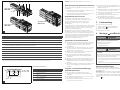 3
3
-
 4
4
-
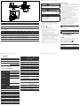 5
5
-
 6
6
-
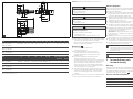 7
7
-
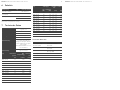 8
8
-
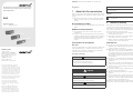 9
9
-
 10
10
-
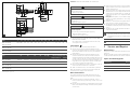 11
11
-
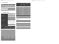 12
12
-
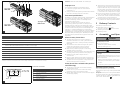 13
13
-
 14
14
-
 15
15
-
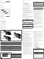 16
16
-
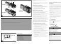 17
17
-
 18
18
-
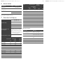 19
19
-
 20
20
-
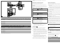 21
21
-
 22
22
-
 23
23
-
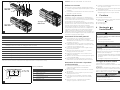 24
24
-
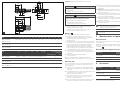 25
25
-
 26
26
-
 27
27
-
 28
28
-
 29
29
-
 30
30
-
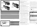 31
31
-
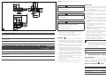 32
32
-
 33
33
-
 34
34
-
 35
35
-
 36
36
-
 37
37
-
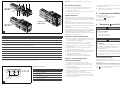 38
38
-
 39
39
-
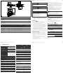 40
40
-
 41
41
-
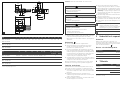 42
42
-
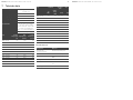 43
43
-
 44
44


AVENTICS Multistage ejector, series EMS Bruksanvisningar
- Typ
- Bruksanvisningar
på andra språk
- italiano: AVENTICS Multistage ejector, series EMS Istruzioni per l'uso
- español: AVENTICS Multistage ejector, series EMS Instrucciones de operación
- Deutsch: AVENTICS Multistage ejector, series EMS Bedienungsanleitung
- français: AVENTICS Multistage ejector, series EMS Mode d'emploi
- English: AVENTICS Multistage ejector, series EMS Operating instructions