Danfoss Link™ HC Hydronic Controller Installationsguide
- Typ
- Installationsguide

Danfoss Link™ HC Hydronic Controller
Installation Guide
Danfoss Heating Solutions
MAKING MODERN LIVING POSSIBLE

3
VIFZL25X © Danfoss 02/2011
SE
FI
NL
PL
CZ
GB
DE
FR
DK
Installation Guide Danfoss Link™ HC
Installation Guide
Installationsanleitung
Guide d’installation
Installationsmanual
Installationshandbok
Asennusohje
Installatiehandleiding
Instrukcja instalacji
Instalační příručka

4
VIFZL25X © Danfoss 02/2011
Installation Guide Danfoss Link™ HC
Introduction . . . . . . . . . . . . . . . . . . . . . . . . . . . . . . . . . . . . . . . . . . . . . . . . . . . . . . . . . . . . . . . . . . . . . . . . . . . . 5
Mounting
1: Mounting on wall . . . . . . . . . . . . . . . . . . . . . . . . . . . . . . . . . . . . . . . . . . . . . . . . . . . . . . . .5
2: Mounting on DIN-rail. . . . . . . . . . . . . . . . . . . . . . . . . . . . . . . . . . . . . . . . . . . . . . . . . . . . 5
Connections
1: Connecting actuators . . . . . . . . . . . . . . . . . . . . . . . . . . . . . . . . . . . . . . . . . . . . . . . . . . . . 6
2: Connecting pump and boiler controls . . . . . . . . . . . . . . . . . . . . . . . . . . . . . . . . . . . . 6
3: Connections for Away Function. . . . . . . . . . . . . . . . . . . . . . . . . . . . . . . . . . . . . . . . . . . 6
4: Connections for Heating & Cooling . . . . . . . . . . . . . . . . . . . . . . . . . . . . . . . . . . . . . . . 7
5: Power supply . . . . . . . . . . . . . . . . . . . . . . . . . . . . . . . . . . . . . . . . . . . . . . . . . . . . . . . . . . . 7
6: Wiring diagram . . . . . . . . . . . . . . . . . . . . . . . . . . . . . . . . . . . . . . . . . . . . . . . . . . . . . . . . . 7
7: External antenna . . . . . . . . . . . . . . . . . . . . . . . . . . . . . . . . . . . . . . . . . . . . . . . . . . . . . . . . 7
Configuration
1: Adding Danfoss Link™ HC to the system. . . . . . . . . . . . . . . . . . . . . . . . . . . . . . . . . . 8
2: Configure Danfoss Link™ HC . . . . . . . . . . . . . . . . . . . . . . . . . . . . . . . . . . . . . . . . . . . . . 8
2a: Configure outputs. . . . . . . . . . . . . . . . . . . . . . . . . . . . . . . . . . . . . . . . . . . . . . . . . . 9
2b: Configure inputs . . . . . . . . . . . . . . . . . . . . . . . . . . . . . . . . . . . . . . . . . . . . . . . . . . . .9
3: Add an output to a room . . . . . . . . . . . . . . . . . . . . . . . . . . . . . . . . . . . . . . . . . . . . . . . . . 9
4: Configure a room . . . . . . . . . . . . . . . . . . . . . . . . . . . . . . . . . . . . . . . . . . . . . . . . . . . . . . .10
5: Remove an output . . . . . . . . . . . . . . . . . . . . . . . . . . . . . . . . . . . . . . . . . . . . . . . . . . . . . . 11
6: Factory reset . . . . . . . . . . . . . . . . . . . . . . . . . . . . . . . . . . . . . . . . . . . . . . . . . . . . . . . . . . . .12
Trouble shooting . . . . . . . . . . . . . . . . . . . . . . . . . . . . . . . . . . . . . . . . . . . . . . . . . . . . . . . . . . . . . . . . . . . . . . . . .13
Technical specifications . . . . . . . . . . . . . . . . . . . . . . . . . . . . . . . . . . . . . . . . . . . . . . . . . . . . . . . . . . . . . . . . . 13
Disposal instructions . . . . . . . . . . . . . . . . . . . . . . . . . . . . . . . . . . . . . . . . . . . . . . . . . . . . . . . . . . . . . . . . . . . . 13
Index

5
VIFZL25X © Danfoss 02/2011
Installation Guide Danfoss Link™ HC
GB
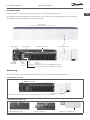
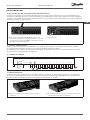
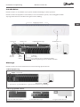
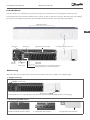
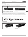
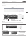
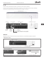
Danfoss Link™ is a wireless control system for a variety of heating systems.
The Danfoss Link™ HC (Hydronic Controller) is a part of this system allowing wireless control of
manifolds for water based floor heating/cooling.
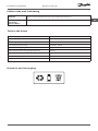
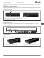
Inputs:
Not in use
Away Function (external ON/OFF switch)
Heating/Cooling (external ON/OFF switch)
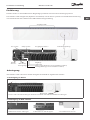
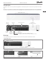
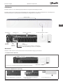
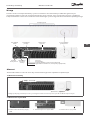
Front
cover
release
External
Antenna
Output LEDs
Install / Link TestOutput connections
Pump relay
Boiler relay
Introduction
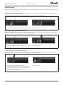
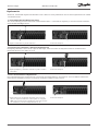
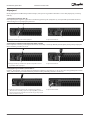
The Danfoss Link™ HC should always be mounted in an horizontal upright position.
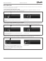
1: Mounting on wall
1. Remove front and side covers and mount with screws and wall plugs.
2: Mounting on DIN-rail
1. Mount DIN-rail parts. 2. Click on DIN-rail. 3. Release from DIN-rail.
Mounting

6
VIFZL25X © Danfoss 02/2011
Installation Guide Danfoss Link™ HC
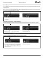
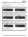
Make sure that all connections to the Danfoss Link™ HC are completed, before connecting to a 230 V
power supply.
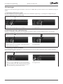
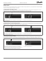
1: Connecting actuators (24 V)
If NC (normally closed) actuators are installed for ON/OFF regulation, no further actuator output con-
figuration is needed.
1. Connect actuator wires to an output. 2. Fix the cable.
2: Connecting pump and boiler controls
The relays for pump and boiler are potential free contacts and can thus NOT be used as direct power
supply. Max. load is 230 V, 8 (2) A.
1. Connect wires for pump and boiler controls to their
respective output.
2. Fix the cable.
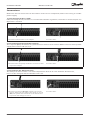
3: Connections for Away Function
The Away Function ensures a set room temperature fixed at 15°C for all Room Thermostats,
but it can be changed with the Danfoss Link™ CC.
1. Connect an external ON/OFF switch to the termi-
nals for Away Function. When this switch is closed
(ON) the system will override all room thermostat
set points and change it to 15°C.
2. Fix the cable.
Connections

7
VIFZL25X © Danfoss 02/2011
Installation Guide Danfoss Link™ HC
GB
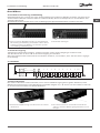
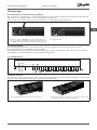
4: Connections for Heating & Cooling
When the system is in cooling mode the actuator output will be activated (ON for NC
actuators / OFF for NO actuators) when the temperature in a room exceeds the set point.
When the system is in cooling mode an independent dew-point alarm function should be installed.
1. Connect an external ON/OFF switch to the
terminals for Heating & Cooling. When this
switch is closed (ON) the system will switch
from heating to cooling.
2. Fix the cable.
5: Power supply
When all actuators, pump and boiler controls and other inputs are installed, connect
the supply plug to a 230 V power supply.
If the power supply plug is removed during installation, make sure that the connection is made ac-
cording to existing law/legislation.
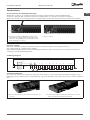
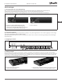
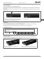
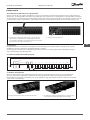
6: Wiring diagram
L
N
9 10876 54321
Actuator outputsRelays
Input
230 V~
50 Hz
External
antenna
L
N
Away
Heating / Cooling
max. 3 m
7: External antenne
The external antenna is installed as diverter when there is no transmission possible through a large
building, heavy construction or metal barrier, e.g. if the Danfoss Link™ HC is located in a metal cabinet/
box
1. Remove the plastic cover from the antenna con-
nection.
2. Connect the external antenna and place it on the
other side of the transmission barrier.
Connections

8
VIFZL25X © Danfoss 02/2011
Installation Guide Danfoss Link™ HC
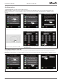
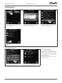
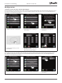
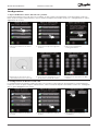
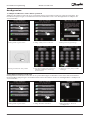
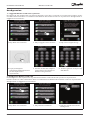
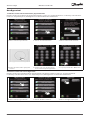
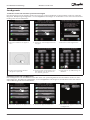
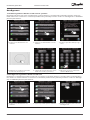
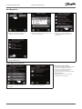
1: Adding Danfoss Link™ HC to the system
Adding Danfoss Link™ HC to a system is made from the Danfoss Link™ CC Central Controller. For
further information, see the Danfoss Link™ CC instruction manual: Configuration 7: Adding service
devices.
1. Select “Rooms and Devices”. 2. Select “Add Service Device”. 3. Select “Begin Registration”.
4. Select Install / Link Test on HC. 5. If wanted, edit room name with
the letter keys.
6. End with pressing “OK/Return”.
2: Configure Danfoss Link™ HC
Configuration Danfoss Link™ HC to a system is made from the Danfoss Link™ CC Central Controller.
For further information, see the Danfoss Link™ CC instruction manual: Configuration 7: Adding service
devices.
1. Select “Rooms and Devices”. 2. Select “Manage Devices”. 3. Select device to configure.
Configuration

9
VIFZL25X © Danfoss 02/2011
Installation Guide Danfoss Link™ HC
GB
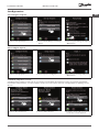
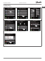
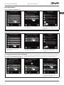
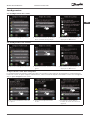
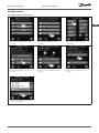
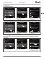
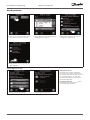
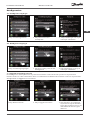
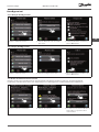
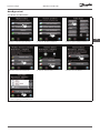
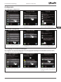
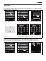
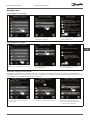
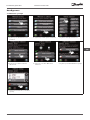
2a: Configure outputs
1. Select “Set up Relays”. 2. Select “Boiler Relay” or “Pump
Relay”.
3. Choose your settings and press
“OK/Return”.
2b: Configure inputs
1. Select “Setup Inputs”. 2. Select input to configure. 3. Choose your settings and press
“OK/Return”.
3: Add an output to a room
Configuration Danfoss Link™ HC to a system is made from the Danfoss Link™ CC Central Controller.
For further information, see the Danfoss Link™ CC instruction manual: Configuration 7: Adding service
devices.
1. Select “Room devices”. 2. Select “Add a device”. 3. If Danfoss Link™ HC is installed,
a selection screen appears.
Configuration

10
VIFZL25X © Danfoss 02/2011
Installation Guide Danfoss Link™ HC
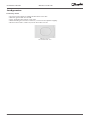
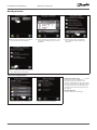
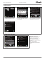
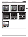
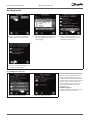
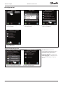
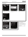
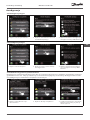
4. If more devices are installed,
select a device.
5. Select output. Only available
outputs are selectable.
6. Select heating emitter and press
“Actuator Settings”.
7. Select actuator type and press
“OK/Return”.
4: Configure a room
• Forecasting method:
by activation of the forecast
method, the system will automati-
cally predict the heating start-up
time necessary to reach desired
room temperature at desired time.
• Regulation type:
only in connection with electrical
heating systems.
1. Select “Heating regulation”. 2. Select type of regulation.
Configuration

11
VIFZL25X © Danfoss 02/2011
Installation Guide Danfoss Link™ HC
GB
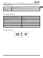
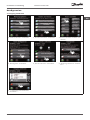
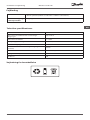
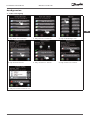
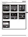
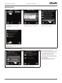
5: Remove an output
1. Select “Rooms and Devices”. 2. Select “Manage Devices”. 3. Select an existing room.
4. Select “Room devices”. 5. Select “Remove a device”. 6. Select “Remove an output”.
7. Select “Yes, remove an output
now”.
Configuration

12
VIFZL25X © Danfoss 02/2011
Installation Guide Danfoss Link™ HC
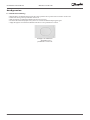
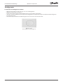
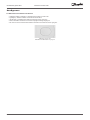
6: Factory reset
• Disconnect the power supply for Danfoss Link™ HC.
• Wait for green LED to turn off.
• Press and hold the Install / Link Test.
• While holding the Install / Link Test, reconnect the power supply.
• Release the Install / Link Test, when the LED’s are on.
Danfoss Link™
HC Install / Link Test
Configuration

13
VIFZL25X © Danfoss 02/2011
Installation Guide Danfoss Link™ HC
GB
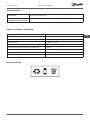
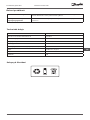
Degraded mode The actuator will be activated with a 25% duty cycle, if the signal from the
room thermostat is lost.
Flashing output /
alarm LED(s)
Output or actuator is short-circuited or the actuator is disconnected.
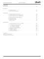
Technical specifications
Transmission Frequency 868.42 Mhz
Transmission range in normal constructions up to 30 m
Transmission power < 1 mW
Supply voltage 230 VAC, 50 Hz
Actuator outputs 10 x 24 VDC
Max. continued output load (total) 35 VA
Relays 230 VAC / 8 (2) A
Ambient temperature 0 - 50°C
IP class 30
Disposal instructions
Trouble shooting

14
VIFZL25X © Danfoss 02/2011
Installationsanleitung Danfoss Link™ HC
Einführung . . . . . . . . . . . . . . . . . . . . . . . . . . . . . . . . . . . . . . . . . . . . . . . . . . . . . . . . . . . . . . . . . . . . . . .15
Anbringung
1: Anbringung an Wand . . . . . . . . . . . . . . . . . . . . . . . . . . . . . . . . . . . . . . . . . . . . . . . . . . . . . . . . . . .15
2: Anbringung an DIN-Schiene . . . . . . . . . . . . . . . . . . . . . . . . . . . . . . . . . . . . . . . . . . . . . . . . . . . 15
Anschlüsse
1: Anschluss von Stellantrieben. . . . . . . . . . . . . . . . . . . . . . . . . . . . . . . . . . . . . . . . . . . . . . . . . . . .16
2: Anschluss von Pumpen- und Kesselreglern . . . . . . . . . . . . . . . . . . . . . . . . . . . . . . . . . . . . . .16
3: Anschlüsse für Abwesenheitsfunktion. . . . . . . . . . . . . . . . . . . . . . . . . . . . . . . . . . . . . . . . . . 16
4: Anschlüsse für Heizung und Kühlung . . . . . . . . . . . . . . . . . . . . . . . . . . . . . . . . . . . . . . . . . . 17
5: Stromversorgung. . . . . . . . . . . . . . . . . . . . . . . . . . . . . . . . . . . . . . . . . . . . . . . . . . . . . . . . . . . . . . 17
6: Schaltbild . . . . . . . . . . . . . . . . . . . . . . . . . . . . . . . . . . . . . . . . . . . . . . . . . . . . . . . . . . . . . . . . . . . . . 17
7: Externe Antenne . . . . . . . . . . . . . . . . . . . . . . . . . . . . . . . . . . . . . . . . . . . . . . . . . . . . . . . . . . . . . . 17
Konfiguration
1: Danfoss Link™ HC zum System hinzufügen . . . . . . . . . . . . . . . . . . . . . . . . . . . . . . . . . . . . . 18
2: Danfoss Link™ HC konfigurieren. . . . . . . . . . . . . . . . . . . . . . . . . . . . . . . . . . . . . . . . . . . . . . . . 18
2a: Ausgänge konfigurieren. . . . . . . . . . . . . . . . . . . . . . . . . . . . . . . . . . . . . . . . . . . . . . . 19
2b: Eingänge konfigurieren . . . . . . . . . . . . . . . . . . . . . . . . . . . . . . . . . . . . . . . . . . . . . . . 19
3: Ausgang zu einem Raum hinzufügen . . . . . . . . . . . . . . . . . . . . . . . . . . . . . . . . . . . . . . . . . . 19
4: Raum konfigurieren . . . . . . . . . . . . . . . . . . . . . . . . . . . . . . . . . . . . . . . . . . . . . . . . . . . . . . . . . . . 20
5: Ausgang entfernen . . . . . . . . . . . . . . . . . . . . . . . . . . . . . . . . . . . . . . . . . . . . . . . . . . . . . . . . . . . . 21
6: Rücksetzen auf Werkseinstellungen. . . . . . . . . . . . . . . . . . . . . . . . . . . . . . . . . . . . . . . . . . . . 22
Fehlersuche und -behebung. . . . . . . . . . . . . . . . . . . . . . . . . . . . . . . . . . . . . . . . . . . . . . . . . . . . . . . . . . . . . 23
Technische Daten . . . . . . . . . . . . . . . . . . . . . . . . . . . . . . . . . . . . . . . . . . . . . . . . . . . . . . . . . . . . . . . . . . . . . . 23
Hinweise zur Entsorgung . . . . . . . . . . . . . . . . . . . . . . . . . . . . . . . . . . . . . . . . . . . . . . . . . . . . . . . . . . . . . . . . 23
Inhaltsverzeichnis

15
VIFZL25X © Danfoss 02/2011
Installationsanleitung Danfoss Link™ HC
DE
Danfoss Link™ ist ein funkbasiertes Regelungssystem für verschiedene Heizungssysteme.
Der Danfoss Link™ Regler HC (Hydronic Controller) ist Teil dieses Systems. Er erlaubt Funksteuerung
von Verteilern für wasserbasierte Fußbodenheizung/-kühlung.
Eingänge:
Unbenutzt
Abwesenheitsfunktion (externer EIN/AUS-Schalter)
Heizung/Kühlung (externer EIN/AUS-Schalter)
Front-
abdeckung -
Entriegelung
Externe
Antenne
Ausgangs-LEDs
Verbindungsprüfung
Ausgangsanschlüsse
PumpenrelaisKesselrelais
Einführung
Der Danfoss Link™ HC muss immer waagerecht und flach angebracht werden.
1: Anbringung an Wand
1. Front- und Seitenabdeckungen abnehmen und mit Schrauben und Dübeln anbringen.
2: Anbringung an DIN-Schiene
1. DIN-Schienenteile anbringen. 2. DIN-Schiene aufschnappen. 3. Von DIN-Schiene lösen.
Anbringung

16
VIFZL25X © Danfoss 02/2011
Installationsanleitung Danfoss Link™ HC
Vor Anschluss einer 230-V-Stromversorgung sicherstellen, dass alle Anschlüsse zum Danfoss Link™ HC
hergestellt sind.
1: Anschluss von Stellantrieben (24 V)
Wenn stromlos geschlossene Stellantriebe (NC) zur EIN/AUS-Regelung installiert sind, muss kein weite-
rer Stellantriebausgang konfiguriert werden.
1. Die Stellantriebkabel an einen Ausgang
anschließen.
2. Das Kabel anbringen.
2: Anschluss von Pumpen- und Kesselreglern
Die Relais für Pumpe und Kessel sind potentialfreie Kontakte und können daher NICHT als direkte
Stromversorgung genutzt werden. Max. Last ist 230 V, 8 (2) A.
1. Kabel für Pumpen- und Kesselregler an ihren
jeweiligen Ausgang anschließen.
2. Das Kabel anbringen.
Anschlüsse
3: Anschlüsse für Abwesenheitsfunktion
Die Abwesenheitsfunktion sorgt für eine festgelegte Raumtemperatur von 15 °C für alle Raumthermo-
state, kann jedoch mit dem Danfoss Link™ CC geändert werden.
1. Einen externen EIN/AUS-Schalter an die Klemmen
für die Abwesenheitsfunktion anschließen. Wenn
dieser Schalter geschlossen (EIN) ist, hebt das Sy-
stem die Sollwerte aller Raumthermostate auf und
ändert sie auf 15 °C.
2. Das Kabel anbringen.

17
VIFZL25X © Danfoss 02/2011
Installationsanleitung Danfoss Link™ HC
DE
Anschlüsse
4: Anschlüsse für Heizung und Kühlung
Bei Kühlbetrieb des Systems wird der Stellantriebausgang aktiviert (EIN bei stromlos geschlossenen
Stellantrieben/AUS bei stromlos offenen Stellantrieben), wenn die Temperatur in einem Raum den
Sollwert übersteigt.
Bei Kühlbetrieb des Systems muss eine unabhängige Taupunktalarmfunktion installiert werden.
1. Einen externen EIN/AUS-Schalter an den Klemmen
für Heizung und Kühlung anschließen. Wenn dieser
Schalter geschlossen (EIN) ist, schaltet das System
von Heizung auf Kühlung um.
2. Das Kabel anbringen.
5: Stromversorgung
Sobald alle Stellantrieb, Pumpen- und Kesselregler sowie andere Eingänge installiert sind,
den Gerätestecker an eine 230-V-Stromversorgung anschließen.
Wird der Gerätestecker während der Installation entfernt, sicherstellen, dass der Anschluss regelge-
recht erfolgt.
6: Schaltbild
L
N
9 10876 54321
Actuator outputsRelays
Input
230 V~
50 Hz
External
antenna
L
N
Away
Heating / Cooling
max. 3 m
7: Externe Antenne
Die externe Antenne wird verwendet, wenn eine Funkübertragung durch große Gebäude, dicke
Wände mit Armierungen oder Metallsperren NICHT möglich ist, z. B. wenn sich der Danfoss Link™ HC
in einem Verteilerschrank aus Metall befindet.
1. Die Kunststoffabdeckung vom Antennen-anschluss
abnehmen.
2. Die externe Antenne anschließen und auf der
anderen Seite des Übertragungshindernisses an-
bringen.

18
VIFZL25X © Danfoss 02/2011
Installationsanleitung Danfoss Link™ HC
1: Danfoss Link™ HC zum System hinzufügen
Das Hinzufügen des Danfoss Link™ HC in einem System erfolgt über den Zentralregler Danfoss Link™
CC. Weitere Informationen finden Sie im Produkthandbuch des Danfoss Link™ CC: Konfiguration 7:
Hinzufügen von Wartungsgeräten
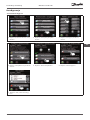
1. „Räume u. Geräte“ auswählen. 2. „Wartungsgerät hinzufügen“
auswählen.
3. „Registrierung beginnen“
auswählen.
4. Verbindungsprüfung an HC
auswählen.
5. Auf Wunsch die
Raumbezeichnung mit den
Buchstabentasten ändern.
6. Mit „OK/Return“ beenden.
2: Danfoss Link™ HC konfigurieren
Die Konfiguration des Danfoss Link™ HC für ein System erfolgt über den Zentralregler Danfoss Link™
CC. Weitere Informationen finden Sie im Produkthandbuch des Danfoss Link™ CC: Konfiguration 7:
Hinzufügen von Wartungsgeräten
1. „Räume u. Geräte“ auswählen. 2. „Geräte verwalten“ auswählen. 3. Das zu konfigurierende Gerät
auswählen.
Konfiguration

19
VIFZL25X © Danfoss 02/2011
Installationsanleitung Danfoss Link™ HC
DE
2a: Ausgänge konfigurieren
1. „Relais einrichten“ auswählen. 2. „Kesselrelais“ oder „Pumpenre-
lais“ auswählen.
3. Die gewünschten Einstellun-
gen wählen und „OK/Return“
drücken.
2b: Eingänge konfigurieren
1. „Einrichten der Eingänge“
auswählen.
2. Die zu konfigurierenden
Eingänge auswählen.
3. Die gewünschten Einstellungen
wählen und „OK/Return“
drücken.
3: Ausgang zu einem Raum hinzufügen
Die Konfiguration des Danfoss Link™ HC für ein System erfolgt über den Zentralregler Danfoss Link™
CC. Weitere Informationen finden Sie im Produkthandbuch des Danfoss Link™ CC: Konfiguration 7:
Hinzufügen von Wartungsgeräten
1. „Raumgeräte“ auswählen. 2. „Gerät hinzufügen“ auswählen. 3. Wenn der Danfoss Link™ HC
installiert ist, wird ein Auswahl-
bildschirm angezeigt.
Konfiguration

20
VIFZL25X © Danfoss 02/2011
Installationsanleitung Danfoss Link™ HC
4. Wenn weitere Geräte installiert
sind, ein Gerät auswählen.
5. Einen Ausgang auswählen. Nur
verfügbare Ausgänge sind aus-
wählbar.
6. Heizungssender auswählen
und „Einstellungen Aktuator“
drücken.
7. Einen Stellantriebtyp auswählen
und „OK/Return“ drücken.
4: Raum konfigurieren
• Adaptive Regelung: Durch
Aktivierung der adaptiven
Regelung prognostiziert das
System automatisch die erforderli-
che Einschaltzeit der Heizung, um
zum gewünschten Zeitpunkt die
gewünschte Raumtemperatur zu
erreichen.
• Regelungsart:
Nur bei Elektroheizungen.
1. „Wärmeregelung“ auswählen. 2. Regelungstyp auswählen.
Konfiguration

21
VIFZL25X © Danfoss 02/2011
Installationsanleitung Danfoss Link™ HC
DE
5: Ausgang entfernen
1. „Räume u. Geräte“ auswählen. 2. „Geräte verwalten“ auswählen. 3. Einen vorhandenen Raum aus-
wählen.
4. „Raumgeräte“ auswählen. 5. „Gerät entfernen“ auswählen. 6. „Ausgang entfernen“ auswäh-
len.
7. „Ja, Ausgang jetzt entfernen“
auswählen.
Konfiguration
Sidan laddas...
Sidan laddas...
Sidan laddas...
Sidan laddas...
Sidan laddas...
Sidan laddas...
Sidan laddas...
Sidan laddas...
Sidan laddas...
Sidan laddas...
Sidan laddas...
Sidan laddas...
Sidan laddas...
Sidan laddas...
Sidan laddas...
Sidan laddas...
Sidan laddas...
Sidan laddas...
Sidan laddas...
Sidan laddas...
Sidan laddas...
Sidan laddas...
Sidan laddas...
Sidan laddas...
Sidan laddas...
Sidan laddas...
Sidan laddas...
Sidan laddas...
Sidan laddas...
Sidan laddas...
Sidan laddas...
Sidan laddas...
Sidan laddas...
Sidan laddas...
Sidan laddas...
Sidan laddas...
Sidan laddas...
Sidan laddas...
Sidan laddas...
Sidan laddas...
Sidan laddas...
Sidan laddas...
Sidan laddas...
Sidan laddas...
Sidan laddas...
Sidan laddas...
Sidan laddas...
Sidan laddas...
Sidan laddas...
Sidan laddas...
Sidan laddas...
Sidan laddas...
Sidan laddas...
Sidan laddas...
Sidan laddas...
Sidan laddas...
Sidan laddas...
Sidan laddas...
Sidan laddas...
Sidan laddas...
Sidan laddas...
Sidan laddas...
Sidan laddas...
Sidan laddas...
Sidan laddas...
Sidan laddas...
Sidan laddas...
Sidan laddas...
Sidan laddas...
Sidan laddas...
Sidan laddas...
Sidan laddas...
Sidan laddas...
Sidan laddas...
Sidan laddas...
Sidan laddas...
-
 1
1
-
 2
2
-
 3
3
-
 4
4
-
 5
5
-
 6
6
-
 7
7
-
 8
8
-
 9
9
-
 10
10
-
 11
11
-
 12
12
-
 13
13
-
 14
14
-
 15
15
-
 16
16
-
 17
17
-
 18
18
-
 19
19
-
 20
20
-
 21
21
-
 22
22
-
 23
23
-
 24
24
-
 25
25
-
 26
26
-
 27
27
-
 28
28
-
 29
29
-
 30
30
-
 31
31
-
 32
32
-
 33
33
-
 34
34
-
 35
35
-
 36
36
-
 37
37
-
 38
38
-
 39
39
-
 40
40
-
 41
41
-
 42
42
-
 43
43
-
 44
44
-
 45
45
-
 46
46
-
 47
47
-
 48
48
-
 49
49
-
 50
50
-
 51
51
-
 52
52
-
 53
53
-
 54
54
-
 55
55
-
 56
56
-
 57
57
-
 58
58
-
 59
59
-
 60
60
-
 61
61
-
 62
62
-
 63
63
-
 64
64
-
 65
65
-
 66
66
-
 67
67
-
 68
68
-
 69
69
-
 70
70
-
 71
71
-
 72
72
-
 73
73
-
 74
74
-
 75
75
-
 76
76
-
 77
77
-
 78
78
-
 79
79
-
 80
80
-
 81
81
-
 82
82
-
 83
83
-
 84
84
-
 85
85
-
 86
86
-
 87
87
-
 88
88
-
 89
89
-
 90
90
-
 91
91
-
 92
92
-
 93
93
-
 94
94
-
 95
95
-
 96
96


Danfoss Link™ HC Hydronic Controller Installationsguide
- Typ
- Installationsguide
på andra språk
Relaterade papper
-
Danfoss Link™ HC Hydronic Controller Installationsguide
-
-
-
-
-
-
-
-
-