Yamaha DPX-1300 Användarmanual
- Kategori
- Dataprojektorer
- Typ
- Användarmanual
Denna manual är också lämplig för

YAMAHA ELECTRONICS CORPORATION, USA 6660 ORANGETHORPE AVE., BUENA PARK, CALIF. 90620, U.S.A.
YAMAHA CANADA MUSIC LTD. 135 MILNER AVE., SCARBOROUGH, ONTARIO M1S 3R1, CANADA
YAMAHA ELECTRONIK EUROPA G.m.b.H. SIEMENSSTR. 22-34, 25462 RELLINGEN BEI HAMBURG, GERMANY
YAMAHA ELECTRONIQUE FRANCE S.A. RUE AMBROISE CROIZAT BP70 CROISSY-BEAUBOURG 77312 MARNE-LA-VALLEE CEDEX02, FRANCE
YAMAHA ELECTRONICS (UK) LTD. YAMAHA HOUSE, 200 RICKMANSWORTH ROAD WATFORD, HERTS WD18 7GQ, ENGLAND
YAMAHA SCANDINAVIA A.B. J A WETTERGRENS GATA 1, BOX 30053, 400 43 VÄSTRA FRÖLUNDA, SWEDEN
YAMAHA MUSIC AUSTRALIA PTY, LTD. 17-33 MARKET ST., SOUTH MELBOURNE, 3205 VIC., AUSTRALIA
Printed in Japan WF80490
C2005 All Rights Reserved.
DPX-1300
U
DIGITAL CINEMA PROJECTOR
PROJECTEUR CINEMA NUMERIQUE
DPX-1300
10_DPX-1300-Cover1-4_U.p65 9/22/05, 4:28 PM1

• Explanation of Graphical Symbols
The lightning flash with arrowhead symbol,
within an equilateral triangle, is intended to alert
you to the presence of uninsulated “dangerous
voltage” within the product’s enclosure that may
be of sufficient magnitude to constitute a risk of
electric shock to persons.
The exclamation point within an equilateral
triangle is intended to alert you to the presence of
important operating and maintenance (servicing)
instructions in the literature accompanying the
appliance.
WARNING
TO REDUCE THE RISK OF FIRE OR ELECTRIC SHOCK,
DO NOT EXPOSE THIS UNIT TO RAIN OR MOISTURE.
1 Read these instructions.
2 Keep these instructions.
3 Heed all warnings.
4 Follow all instructions.
5 Do not use this apparatus near water.
6 Clean only with dry cloth.
7 Do not block any ventilation openings. Install in accordance
with the manufacturer’s instructions.
8 Do not install near any heat sources such as radiators, heat
registers, stoves, or other apparatus (including amplifiers) that
produce heat.
9 Do not defeat the safety purpose of the polarized or grounding-
type plug. A polarized plug has two blades with one wider than
the other. A grounding type plug has two blades and a third
grounding prong. The wide blade or the third prong are
provided for your safety. If the provided plug does not fit into
your outlet, consult an electrician for replacement of the
obsolete outlet.
10 Protect the power cord from being walked on or pinched
particularly at plugs, convenience receptacles, and the point
where they exit from the apparatus.
11 Only use attachments/accessories specified by the
manufacturer.
12 Use only with the cart, stand, tripod, bracket,
or table specified by the manufacturer, or sold
with the apparatus. When a cart is used, use
caution when moving the cart/apparatus
combination to avoid injury from tip-over.
13 Unplug this apparatus during lightning storms
or when unused for long periods of time.
14 Refer all servicing to qualified service personnel. Servicing is
required when the apparatus has been damaged in any way,
such as power-supply cord or plug is damaged, liquid has been
spilled or objects have fallen into the apparatus, the apparatus
has been exposed to rain or moisture, does not operate
normally, or has been dropped.
15 Be sure to allow spaces of at least 30cm above, behind and on
both sides the unit.
16 Do not place the following objects on this unit:
A vessel with water in it. If the vessel falls by vibrations and
water spills, it may cause damage to the unit, and/or you may
get an electric shock.
IMPORTANT!
Please record the serial number of this unit in the space below.
Model:
Serial No.:
The serial number is located on the bottom of the unit.
Retain this Owner’s Manual in a safe place for future reference.
CAUTION
RISK OF ELECTRIC SHOCK
DO NOT OPEN
CAUTION: TO REDUCE THE RISK OF
ELECTRIC SHOCK, DO NOT REMOVE
COVER (OR BACK). NO USER-SERVICEABLE
PARTS INSIDE. REFER SERVICING TO QUALIFIED
SERVICE PERSONNEL.
IMPORTANT SAFETY INSTRUCTIONS
i
10_DPX-1300-ULCaut_E.p65 9/20/05, 4:00 PM1

FCC INFORMATION (for US customers only)
1. IMPORTANT NOTICE: DO NOT MODIFY THIS
UNIT!
This product, when installed as indicated in the instructions
contained in this manual, meets FCC requirements.
Modifications not expressly approved by Yamaha may void
your authority, granted by the FCC, to use the product.
2. IMPORTANT: When connecting this product to accessories
and/or another product use only high quality shielded
cables. Cable/s supplied with this product MUST be used.
Follow all installation instructions. Failure to follow
instructions could void your FCC authorization to use this
product in the USA.
3. NOTE: This product has been tested and found to comply
with the requirements listed in FCC Regulations, Part 15 for
Class “B” digital devices. Compliance with these
requirements provides a reasonable level of assurance that
your use of this product in a residential environment will not
result in harmful interference with other electronic devices.
This equipment generates/uses radio frequencies and, if not
installed and used according to the instructions found in the
users manual, may cause interference harmful to the operation
of other electronic devices.
Compliance with FCC regulations does not guarantee that
interference will not occur in all installations. If this product is
found to be the source of interference, which can be determined
by turning the unit “OFF” and “ON”, please try to eliminate the
problem by using one of the following measures:
Relocate either this product or the device that is being affected
by the interference.
Utilize power outlets that are on different branch (circuit
breaker or fuse) circuits or install AC line filter/s.
In the case of radio or TV interference, relocate/reorient the
antenna. If the antenna lead-in is 300 ohm ribbon lead, change
the lead-in to coaxial type cable.
If these corrective measures do not produce satisfactory results,
please contact the local retailer authorized to distribute this type
of product. If you can not locate the appropriate retailer, please
contact Yamaha Electronics Corp., U.S.A. 6660 Orangethorpe
Ave, Buena Park, CA 90620.
The above statements apply ONLY to those products distributed
by Yamaha Corporation of America or its subsidiaries.
We Want You Listening For A Lifetime
YAMAHA and the Electronic Industries Association’s Consumer Electronics Group want you to get the most out of your
equipment by playing it at a safe level. One that lets the sound come through loud and clear without annoying blaring or
distortion – and, most importantly, without affecting your sensitive hearing. Since hearing damage from loud sounds is often
undetectable until it is too late, YAMAHA and the Electronic Industries Association’s Consumer Electronics Group recommend
you to avoid prolonged exposure from excessive volume levels.
COMPLIANCE INFORMATION STATEMENT
(DECLARATION OF CONFORMITY PROCEDURE)
Responsible Party: Yamaha Electronics Corporation
Address: 6660 Orangethorpe Avenue
Buena Park, CA90620
Telephone: 714-522-9105
Fax: 714-670-0108
Type of Equipment: Projector
Model Name: DPX-1300
This device complies with Part 15 of the FCC Rules.
Operation is subject to the following conditions:
1) this device may not cause harmful interference, and
2) this device must accept any interference received including interference that may cause undesired operation.
See the user manual instructions if interference to radio reception is suspected.
ii
10_DPX-1300-ULCaut_E.p65 9/20/05, 4:00 PM2

English
Caution: Read this before operating this unit.
•To assure the finest performance, please read this manual
carefully. Keep it in a safe place for future reference.
Installation
• Install this unit in a well-ventilated, cool, dry, clean place with
at least 30 cm (1 feet) clearance on the top, right and left, and
at the back of this unit — away from direct sunlight, heat
sources, vibration, dust, moisture, and/or cold.
• Locate this unit away from other electrical appliances, motors,
or transformers to avoid humming sounds. To prevent fire or
electrical shock, do not place this unit where it may get
exposed to rain, water, and/or any type of liquid.
• Do not expose this unit to sudden temperature changes from
cold to hot, and do not locate this unit in an environment with
high humidity (i.e. a room with a humidifier) to prevent
condensation inside this unit, which may cause an electrical
shock, fire, damage to this unit, and/or personal injury.
• On the top of this unit, do not place:
– Other components, as they may cause damage and/or
discoloration on the surface of this unit.
– Burning objects (i.e. candles), as they may cause fire,
damage to this unit, and/or personal injury.
– Containers with liquid in them, as they may cause electrical
shock to the user and/or damage to this unit.
• Do not cover this unit with a newspaper, tablecloth, curtain, etc.
in order not to restrict heat dissipation. If the temperature inside
this unit rises too much, it may cause fire, damage to this unit,
and/or personal injury.
•When installing this unit on the ceiling, make sure the ceiling
has sufficient strength to support this unit and the ceiling
mounts for an extended period of time. Installation must be
performed only by qualified service personnel.
• Install this unit near the AC outlet and where the AC power
plug can be reached easily.
Operation
• Remove the lens cover before starting any operation of this unit
to prevent the heat from staying around the lens. Operation
with the cap on may cause damage to this unit.
• Do not plug in this unit to a wall outlet until all connections are
complete.
• Only the voltage specified on this unit must be used. Using this
unit with a higher voltage than specified is dangerous and may
cause fire, damage to this unit, and/or personal injury.
YAMAHA will not be held responsible for any damage
resulting from use of this unit with a voltage other than that
specified.
• Do not use force on switches, knobs and/or cords.
•Take care of this unit so that no foreign objects and/or liquid
drop inside this unit.
•To prevent damage by lightning, keep the power cord out and
outdoor antennas disconnected from a wall outlet or te unit
during the lightning storm.
• Do not look into the lens while this unit is turned on. It may
cause serious damage to your eyesight.
• Before moving this unit, press STANDBY/ON to set this unit
in the standby mode, and disconnect the AC power plug from
the wall outlet.
• Do not attempt to modify or fix this unit. Contact qualified
YAMAHA service personnel when any service is needed. The
cabinet should never be opened for any reason.
• When not planning to use this unit for a long period of time
(i.e. vacation), disconnect the AC power plug from the wall
outlet.
•When disconnecting the power cord from the wall outlet, grasp
the plug; do not pull the cable.
• Be sure to read the “Troubleshooting” section on common
operating errors before concluding that this unit is faulty.
Others
• Clean the lens carefully so as not to create any scratches by
using a blower or lens paper.
•Replace the lamp when the LAMP warning indicator blinks in
red after the lamp usage has exceeded 2000 hours. Follow the
lamp replacement procedure described in this manual.
For U.K. customers
If the socket outlets in the home are not suitable for the plug
supplied with this appliance, it should be cut off and an appropriate
3 pin plug fitted. For details, refer to the instructions described
below.
Note
•The plug severed from the mains lead must be destroyed, as a plug with
bared flexible cord is hazardous if engaged in a live socket outlet.
IMPORTANT
THE WIRES IN THIS MAINS LEAD ARE COLOURED IN
ACCORDANCE WITH THE FOLLOWING CODE:
GREEN-AND-YELLOW: EARTH
BLUE: NEUTRAL
BROWN: LIVE
As the colours of the wires in the mains lead of this apparatus may
not correspond with the coloured markings identifying the
terminals in your plug, proceed as follows:
The wire which is coloured GREEN-AND-YELLOW must be
connected to the terminal in the plug which is marked by the letter
E or by the safety earth symbol or coloured GREEN or GREEN-
and-YELLOW.
The wire which is coloured BLUE must be connected to the
terminal which is marked with the letter N or coloured BLACK.
The wire which is coloured BROWN must be connected to the
terminal which is marked with the letter L or coloured RED.
For Canadian customers
To prevent electric shock, match wide blade of plug to
wide slot and fully insert.
This Class B digital apparatus complies with Canadian ICES-
003.
iii
10_DPX-1300-ULCaut_E.p65 9/20/05, 4:00 PM3

1
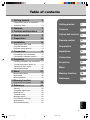
Table of contents
1 Getting started 2
Inappropriate places for installation ....... 2
Accessory check .................................... 2
2 Features 3
3 Controls and functions 4
4 Remote control 6
5 Preparation 10
6 Installation 12
Setting up the DPX-1300 ..................... 12
Projection distance ............................... 13
Projection image position ..................... 14
7 Connection 15
Connecting to AV components ............. 15
Connecting to computer devices ......... 16
8 Projection 17
Checking installation and connections...
17
Turning the projector power on ............ 18
Selecting an input signal ...................... 20
Adjusting the image ............................. 25
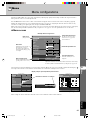
9 Menu 27
Menu configurations ............................ 27
Menu items .......................................... 28
Menu operations .................................. 38
10
Memory function
(Saving, Recall, Lock, Copy, Reset) 48
11
Reference 55
Glossary ............................................... 55
Compatible signal types ....................... 56
Maintenance ......................................... 58
Troubleshooting.................................... 60
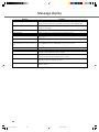
Message display .................................. 62
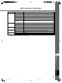
LED Indicator meanings ....................... 63
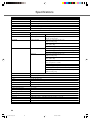
Specifications ....................................... 64
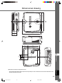
Dimensional drawing ............................ 65
Getting started
Features
Controls and functions
Remote control
Preparation
Projection
Menu
Memory function
Reference
11
10
9
8
7
6
5
4
3
2
1
Connection
Installation
English
11_DPX-1300_E.p65 9/20/05, 4:00 PM1

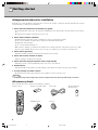
2
◆Inappropriate places for installation
If this unit is not correctly installed in an appropriate place, it may cause fire or failure, or damage the unit itself. Carefully choose the place
to install this unit by avoiding the places listed below.
1. Places where the temperature and humidity vary greatly
• Do not install this unit in a place where the temperature and humidity become extremely high or the temperature becomes extremely
low.
• This unit must be used within a temperature range of 5 to 35°C.
2. Places without adequate ventilation
• Install this unit with at least 30 cm (1 feet) of ventilation space on the top, right and left, and back.
• Do not cover the ventilation slots of this unit. Covering the slots will obstruct heat dissipation.
• Install this unit on the firm surface.
• Do not cover this unit with a tablecloth, etc.
• Make sure there is nothing to get sucked into the ventilation slots so that the temperature of this unit does not become too high.
• If you are going to install the unit in a rack, be sure to leave space for ventilation to prevent exhaust overheating the unit.
3. Places where it gets dusty
• If the filter is blocked with dust, the temperature of this unit may become too high.
4. Places with too much vibration or impact
•Vibration and impact can damage parts of this unit.
5. Places where this unit gets exposed to water or high humidity
• If this unit is exposed to water or high humidity, it may cause a fire or electrical shock.
6. Unstable places
• If this unit is installed on an unstable or an inclined tabletop, it may fall and cause damage to the unit or personal injury.
7. In close proximity to a Radio or Stereo
•The unit may interfere with reception if placed in close proximity to a radio or television receiver.
Warning
•To ensure vivid, high contrast images, make sure that no light other than the projector light falls directly on the screen.
◆Accessory check
Please check that all accessories listed here are included in your package.
• Remote control • Batteries (AA, UM-3 or R6) • Power cable
• Pin/BNC adapters • Lens cap
1 Getting started
• Trigger-out DC plug
(For USA only)
45
RESET
6
123
VIDEO
STILL
HIDE
PATTIRIS
AUTO
SETTING
ZOOM FOCUSV. POS
LIGHT
B
D4
DVI
S VIDEO
A
INPUT
MEMORY
HDMI
INPUT
MENU
ASPECT
ESCAPE
11_DPX-1300_E.p65 9/20/05, 4:00 PM2

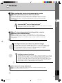
3
Features
2
English
Adjust 7 colors independently (including white), or use the
automatic color balance function
The DPX-1300 allows you to adjust the 7-axis WRGBYCM color coordinate and gain
parameters directly. For better consistency, you can also control color temperature and RGB
balance together, allowing you to check that the changes you make are always consistent with
your preferences.
The digital interface provides sharp, detailed images
The DPX-1300 is equipped with an HDMI terminal, which is set to become the standard for the
coming generation of products. Connect to a DVD player or set-top box with a HDMI terminal
to receive digital image data directly, and enjoy completely digitally processed images.
Compatible with the content protection function of HDCP.
Intelligent memory functions
The DPX-1300 can store six image memory settings, called memory numbers, for each input
jack. For each memory number, you can set parameters for different input resolutions, and the
unit will switch to the appropriate parameters when it begins displaying an image of an
appropriate resolution. For example, the unit automatically changes display settings without
changing memory numbers when you change from watching a DVD to watching a HDTV
image for which you have set different image menu item parameters.
In-line menus for image adjustment
You can access image adjustment menu items at the touch of a button, and adjust images while
viewing them without opening the menu screen.
Highly configurable electronic adjustment gives you the
freedom to place the projector wherever you want
A short focal length, high power zoom, and fully vertically adjustable lens allow you to use the
projector in a wide range of environments. You can also use the remote control to access many
lens functions such as focus, zoom, and lens shift to fine-tune the projector from your viewing
position.
Uses the DMD
TM
device 720p DarkChip3
TM
The projector uses the high contrast “720p DarkChip3
TM
”, to reduce black levels even further
and reproduce contrasts close to that of a film.
2 Features
11_DPX-1300_E.p65 9/20/05, 4:00 PM3

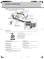
4
◆Main unit <Front panel and controls>
STANDBY
/
ON
SETTING
LAMP COVER TEMP FAN
PATTERN
ESCAPE
MENU
INPUT
DIGITAL CINEMA PROJECTOR DPX-1300
ASPECT
1
2
3
4
5
1
6
7
8
9
0
STANDBY
/
ON
SETTING
LAMP COVER TEMP FAN
PATTERN
ESCAPE
MENU
INPUT
ASPECT
A
E
B
CD
2 STANDBY/ON button
Switches the unit between Standby and On (operational)
modes.
3 ESCAPE button
Exits from submenus.
4 PATTERN button
Switches the built-in test pattern on and off.
5 ASPECT button
Turns the display aspect menu for the project image on and off.
6 (Enter) button
Sets values when the DPX-1300 is displaying the menu. When
the menu is not displayed, the DPX-1300 displays the in-line
image quality adjustment menu. (☞ page 47)
1 LED Indicators
The main unit is equipped with 5 indicators to display various states of operation. See page 63 for explanations of the LED indicator
meanings.
7 MENU button
Switches the settings and adjustments menu display on and off.
8 SETTING button
Selects lens adjustment modes.
9 INPUT button
Switches the input signal selection menu display on and off.
0 Cursor buttons
Use the h, g, +, - buttons for system operations, menu item
selection, and changing system values.
A STANDBY/ON indicator
(There is also an LED on the front panel of the main unit.)
B LAMP warning indicator
C COVER warning indicator
D TEMP warning indicator
E FAN warning indicator
Lamp cover
Ventilation inlet
Adjustable feet
Makes small adjustments to
the projection angle
Lens
Exhaust vent
Front remote control sensor
STANDBY/ON indicator
3 Controls and functions
Lens cap
11_DPX-1300_E.p65 9/20/05, 4:00 PM4

5
Controls and functions
3
English
HDMIDVI
G/Y B/P
B
/C
B
R/P
R
/C
R
INPUT A
HD/SYNC
VD
OUT IN
REMOTE
TRIGGER OUT
S VIDEO VIDEO
INPUT B
RGB/YP
B
P
R
/YC
B
C
R
RS-232C
D4 VIDEO
wq
8
765432190
ert
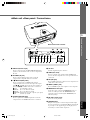
◆Main unit <Rear panel / Connections>
1 INPUT B (D-sub 15 pin)
Receives component video and RGB (RGB/YPBPR/YCBCR)
signals. Use a D-sub monitor cable to connect components to
this jack.
2 D4 VIDEO (D jack)
Receives signals output from the D jacks of other AV
components. It is compatible with D1 - D4 formats.
3 - 7 INPUT A (BNC jacks)
Receive component video and RGB signals. Connect
component signal connectors from AV components to input
jacks 3 - 5, and RGB signal connectors from computers to
input jacks 3 - 7. Use BNC cables for these connections.
3 G/Y (G, or luminance signal)
4 B/P
B/CB (B, or color difference signal)
5 R/PR/CR (R, or color difference signal)
6 HD/SYNC (Horizontal sync signal, composite sync signal)
7 VD (Vertical sync signal)
8 S VIDEO (Mini DIN jack)
Receives signals from S-VIDEO output jacks of other AV
components. Use an S-VIDEO cable for these connections.
9 AC inlet
Insert the supplied AC power cable here.
0 VIDEO (Pin Jack)
Receives composite video signals from the VIDEO output
jacks of other AV components. Use a video pin cable for these
connections.
q DVI (DVI jack)
Receives RGB signals from computers or AV components. Use
a DVI cable for this connection.
w HDMI
TM
(HDMI
TM
jack)
Receives HDMI
TM
signals from computers or AV components.
e REMOTE IN / OUT jack
Connect the remote control to the REMOTE IN jack if you
want to use it through a cable. The REMOTE OUT jack
outputs the signal received through the REMOTE IN jack
without any change.
r RS-232C (D-sub 9 pin)
For use in servicing this unit.
t TRIGGER OUT
Outputs control signals to external components. This output
provides a potential of 12 V/ maximum 200 mA when this unit
is projecting. Use the supplied trigger-out DC plug (for US
model only) to control external components.
Rear remote control sensor
11_DPX-1300_E.p65 9/20/05, 4:00 PM5

6
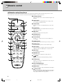
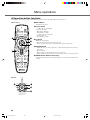
◆ Remote control functions
Buttons on the remote control with identical names to those on the main unit perform identical functions. When using the remote control,
point it at the remote control sensor on the front or back of the main unit from a distance of 7m (23 feet) or less.
1 Transmit indicator
Lights up when the remote control sends infrared signals to the
main unit.
2 AUTO button
Automatically sets the DPX-1300 to the best settings for the
type of signal it is currently receiving.
3 V.POS button
Switches on or off the vertical adjustment mode for the entire
image.
4 ZOOM button
Switches on or off the size adjustment mode for the image the
DPX-1300 is projecting.
5 IRIS button
Switches on or off the lens iris change mode.
6 ESCAPE button
Exits from submenus.
7 Cursor buttons
Use the h ,g, +, - buttons to move the cursor within the on-
screen display.
8 ASPECT button
Turns the display aspect menu for the project image on and off.
9 RESET button
Resets all adjustable parameters to their default settings.
0 STILL button
Stops a moving image, displaying a still of the image the DPX-
1300 is projecting. Press STILL again to cancel this effect.
q INPUT area
Selects the INPUT jacks directly.
w MEMORY area
Calls stored memory (all parameter settings) directly.
e button
Switches the unit between Standby and On (operational)
modes.
r FOCUS button
Switches on or off the focus adjustment mode for the image the
DPX-1300 is projecting.
t PATT (PATTERN) button
Switches on and off the built-in test pattern.
y MENU button
Switches on and off the settings and adjustments menu display.
u (Enter) button
Sets values when the DPX-1300 is displaying the menu. When
the menu is not displayed, the DPX-1300 displays the in-line
image quality adjustment menu. (☞ page 47)
4 Remote control
45
RESET
6
123
VIDEO
STILL
HIDE
PATTIRIS
AUTO
SETTING
ZOOM FOCUSV. POS
LIGHT
B
D4
DVI
S VIDEO
A
INPUT
MEMORY
HDMI
INPUT
MENU
ASPECT
ESCAPE
o
i
u
y
t
p
r
e
1
2
3
4
5
6
7
8
9
0
q
w
11_DPX-1300_E.p65 9/20/05, 4:00 PM6

7
Remote control
4
English
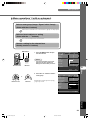
i INPUT button
Switches on and off the input signal selection menu display.
o LIGHT switch
Moving this switch lights the high-use AUTO (2), ESCAPE
(6), ASPECT(8) ,
(e), MENU (y), and INPUT (i)
buttons. The light disappears if you do not perform any
operation within 10 seconds.
p HIDE button
Temporarily halts projection of the image the DPX-1300 is
currently displaying. Press again to cancel this effect.
a Remote control code switch
Selects ID-1 or ID-2 when operating two main units with one
remote control. You can set the ID for the main unit in the
menu (The default setting is ID-1).
s Remote control cable jack
Connect this jack and REMOTE IN jack on the main unit using
a cable (commercially available) to use the remote control with
a wired connection. (☞ page 8)
INPUT
I
RIS
V
.POS
AU
T
O
PATT
FO
C
US
ZO
O
M
S
E
T
T
I
N
G
I
D-2
ID
-
1
RESET
H
ID
E
ST
I
L
L
S VIDEO
VIDEO
B
D4
A
DVI
4
5
6
1
2
3
HDMI
MEMORY
LIGHT
INPUT
MENU
E
SCAPE
ASPECT
a
s
11_DPX-1300_E.p65 9/20/05, 4:00 PM7

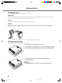
8
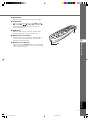
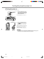
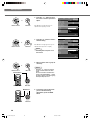
◆Loading the batteries into the remote control
1. Remove the battery compartment cover.
2. Insert two batteries (AA, UM3, or R6 type), matching the polarity
markings on the batteries with those in the battery
compartment.
3. After loading the batteries, close the cover until it snaps into
place.
Warning
• If the remote control must be used closer to the main unit than normal, or does not always operate correctly, exchange the
batteries for new ones.
• Do not mix old and new, or different types of batteries.
• Remove the batteries if you do not plan to use the unit for a long time.
• If the batteries leak, dispose of them immediately, taking care not to touch the battery fluid. If the battery fluid comes into contact
with your eyes, mouth, or skin, rinse it off with water immediately and consult a doctor. Clean the battery compartment thoroughly
before installing new batteries.
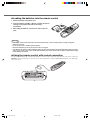
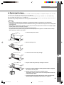
◆Using the remote control with a wired connection
Use a 2P monaural miniplug cable (commercially available) to connect the remote control jack on the underside of the remote control to the
REMOTE IN jack on the main unit. Use the wired remote control configuration to control the DPX-1300 without having to be within range
of the remote sensor.
1
3
2
IR
IS
V
.P
OS
A
U
T
O
PAT
T
FOCUS
ZOOM
SE
T
T
I
N
G
ID
-
2
I
D
-1
R
ESET
H
IDE
STIL
L
4
5
6
1
2
3
LIGH
T
I
N
PU
T
ME
N
U
ES
CAPE
AS
P
ECT
INPU
T
INPUT
S
V
IDE
O
VID
E
O
B
D4
A
D
V
I
HD
MI
HDMIDVI
G/Y B/P
B
/C
B
R/P
R
/C
R
INPUT A
HD/SYNC VD
OUT IN
REMOTE
TRIGGER OUT
S-VIDEO VIDEO
INPUT B
RGB/YP
B
P
R
/YC
B
C
R
RS-232C
D4 VIDEO
11_DPX-1300_E.p65 9/20/05, 4:00 PM8

9
Remote control
4
English
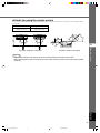
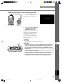
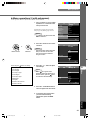
Distance to sensor Angle to sensor
7 m 30˚ vertically and horizontally
(approximate value) (approximate value)
◆ Limits for using the remote control
Use the remote control within the following parameters. The remote control may not function correctly if you use it outside the limits
described here.
Warning
• Bright or fluorescent light on the main unit remote sensor may inhibit the functioning of the remote control.
• Objects placed between the main unit remote sensor and the remote control may block the remote control signal and inhibit
functioning.
Use within a left/right arc of 30 degrees Use within a vertical arc of 30 degrees
HDMI
G/Y B/P
B
/C
B
R/P
R
/C
R
INPUT A
HD/SYNC
VD
OUT IN
REMOTE
TRIGGER OUT
S-VIDEO VIDEO
INPUT B
RGB/YP
B
P
R
/YC
B
C
R
RS-232C
D4 VIDEO
45
RESET
6
123
VIDEO
STILL
HIDE
PATTIRIS
AUTO
SETTING
ZOOM FOCUSV. POS
LIGHT
BDVI
S VIDEO
A
D4
INPUT
MEMORY
HDMI
INPUT
MENU
ASPECT
ESCAPE
45
RESET
6
123
VIDEO
STILL
HIDE
PATTIRIS
AUTO
SETTING
ZOOM FOCUSV. POS
LIGHT
B DVI
S VIDEO
A
D4
INPUT
MEMORY
HDMI
INPUT
MENU
ASPECT
ESCAPE
11_DPX-1300_E.p65 9/20/05, 4:00 PM9

10
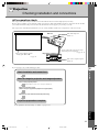
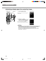
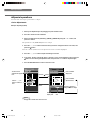
Before projection, install the main unit and a screen, connect the main unit to an AV component or computer, and adjust the projection image.
You can begin projection as soon as installation is complete.
Refer to the sections below for information on how to install the main unit to suit your viewing environment.
◆If you have not installed the main unit or screen
• Immediately after purchase, when you have not installed either the main unit or a screen.
• When moving the main unit and screen to a new location.
◆If you have installed the main unit and screen, and connected a
source component
• You have installed the main unit and screen, and connected source components.
• You are using the main unit in a previously installed location with previously connected source components.
◆If you have installed the main unit and screen, but not connected
any image playback components
• You have installed the main unit and screen, but not connected any source components.
• You are using the main unit in a previously installed location, and wish to change the component you use as a signal source.
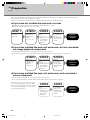
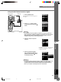
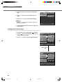
You do not need to carry out step 3 or step 4 if you
do not want to adjust the projection image. If the
unit does not project the image correctly, it may not
be connected correctly. In this case, carry out this
procedure starting from step 2.
STEP3
Select an image and
project.
☞ page 17 - 26
• The image is used
for adjusting the
image position
and focus.
STEP4
Adjust the
projection image.
☞ page 27 - 47
• Use the menu to
adjust projection
details.
Projection
preparations
complete
STEP2
Connect AV
components or a
computer to the
main unit.
☞ page 15 - 16
STEP3
Select an image and
project.
☞ page 17 - 26
• The image is used
for adjusting the
image position
and focus.
STEP4
Adjust the
projection image.
☞ page 27 - 47
• Use the menu to
adjust projection
details.
Projection
preparations
complete
STEP 1
Install the main unit
and screen.
☞ page 12
STEP3
Select an image and
project.
☞ page 17 - 26
• The image is used
for adjusting the
image position
and focus.
STEP2
Connect AV
components or a
computer to the
main unit.
☞ page 15 - 16
Projection
preparations
complete
5
Preparation
STEP4
Adjust the
projection image.
☞ page 27 - 47
• Use the menu to
adjust projection
details.
11_DPX-1300_E.p65 9/20/05, 4:00 PM10

11
Prepararion
5
English
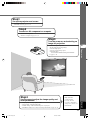
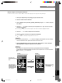
Step2
Connect an AV component or computer
• Connect AV components
• Connect a computer ☞ page 15 - 16
Step3
Turn the power on and selecting an
image for projection
•Turn on the projector power
•Begin playback of the input image
• Select an input signal
• Select a projection image aspect
• Adjust the image
Focus/Vertical and Horizontal position/Size/Iris
☞ page 17 - 26
Step1
Set up the projector and screen
• Install the projector
• Install the screen ☞ page 12 - 14
Only adjust these
parameters when
necessary. It is not
necessary to adjust these
settings once you have set
them initially.
Step4
Use the menu to adjust the image quality and
other parameters
• Image quality: Set image quality details
• Signal setting: Set input signal details
• Default settings: Set the default settings for everyday use
• Installation settings: Set to suit your viewing environment ☞ page 27 - 47
11_DPX-1300_E.p65 9/20/05, 4:00 PM11

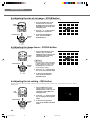
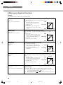
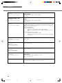
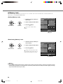
12
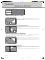
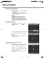
Setting up the DPX-1300
◆ Mounting the projector on a table
A: From in front of a screen
Place the unit on a table to project and view the image from in front of the screen. Usually,
place the unit on a reasonably high table. The height from the bottom of the unit to the center
of the lens is 12.4 cm (4”-7/8).
B: From behind a screen (using a semi-translucent screen)
Place the unit on a table to project and view the image from behind a semi-translucent
screen. The distance between the projector and the screen should be the same as “A: From in
front of the screen”.
• Set the [Location] menu item in the [Setup] menu group to [Rear/Table]. (☞ page 27 - 47)
◆ Mounting the projector on the ceiling
There are two kinds of brackets (sold separately: PMT-L31 and PMT-H35), which you can use to mount the projector on the ceiling. Please
consult your dealer for details on their use, and have installation done by either your dealer or a reputable contractor.
C: From in front of a screen
Mount the unit on the ceiling to project and view the image from in front of the screen. The
distance between the projector and the screen should be the same as “A: From in front of the
screen”.
•
Set the [Location] menu item in the [Setup] menu group to [Front/Ceiling]. (☞ page
27 - 47
)
D: From behind a semi-translucent screen
Mount the unit on the ceiling to project and view the image from behind a semi-translucent
screen. The distance between the projector and the screen should be the same as “B: From
behind a screen”.
•
Set the [Location] menu item in the [Setup] menu group to [Rear/Ceiling]. (☞ page
27 - 47
)
There are four ways of mounting the projector.
6
Installation
Mounting method
Placed on a table
Mounted on the
ceiling
Projection method
A: From in front of a screen
C: From in front of a screen
B: From behind a semi-translucent screen
D: From behind a semi-translucent screen
11_DPX-1300_E.p65 9/20/05, 4:00 PM12

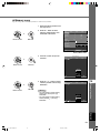
13
Installation
6
English
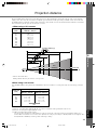
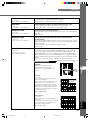
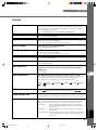
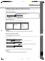
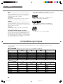
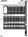
The most suitable distance between the screen and the projector (see Projection distance [a]) depends on the size of the screen (diagonal
length) you use. You can use the zoom function to adjust the projection distance within a preset range from Wide to Tele. You can also alter
the V.POS parameter to adjust the vertical position of the image to better suit the screen. Use the information in the table below to determine
the best location to place the projector in to suit your screen size.
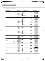
Projection distance
<When using a 4:3 screen>
Since the DPX-1300 has a 16:9 panel, the ideal installation location for use with a 4:3 screen depends on the size of the image you wish to
view.
<When using a 16:9 screen>
60'' 80'' 100'' 150'' 200''
*These are theoretical values.
During actual use there may be a deviance of a few percent.
(*1) Projects a 16:9 image that completely fills the screen (leaves a black line at the top and bottom of the screen).
(*2) Projects a 4:3 image that completely fills the screen.
(*3) When projecting both 16:9 and 4:3 images.
You can use the zoom function to make efficient use of the screen for both *1 and *2 above. The projection distance in this case is
between Wide in *2 and Tele in *1. Use the zoom to adjust the size of the projection images so that they fill the screen completely. Note
that adjustments to V.POS may cause the position of the image to change.
Projection distance [a]
Lens
centerline
Screen size
60
70
80
90
100
110
120
150
200
Screen size
(inch)
1.78 – 2.88
2.08 – 3.37
2.39 – 3.86
2.70 – 4.35
3.00 – 4.84
3.31 – 5.33
3.62 – 5.82
4.54 – 7.29
6.07 – 9.74
Projection distance [a]
Wide (m) – Tele (m)
Screen size
(inch)
16:9 image (*1)
Wide (m) – Tele (m)
4:3 image (*2)
Wide (m) – Tele (m)
Projection distance[a]
60
80
100
120
200
1.63 – 2.64
2.19 – 3.54
2.76 – 4.44
3.32 – 5.34
5.58 – 8.94
2.17 – 3.52
2.93 – 4.72
3.68 – 5.92
4.43 – 7.12
7.43 – 11.92
(*3)
11_DPX-1300_E.p65 9/20/05, 4:00 PM13

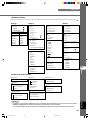
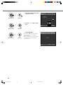
14
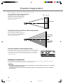
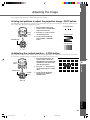
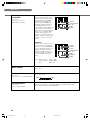
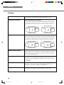
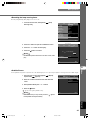
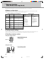
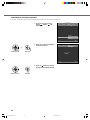
Follow the instructions to adjust the position of the projected image on screen.
<Using ZOOM to adjust image position>
This illustration shows the limits within which the
zoom function can alter projection distance [a] in
relation to screen size. You can adjust the image
within these limits so that it fills the screen
completely. ( ☞ page 26)
<Using V.POS (vertical position) to adjust image position>
You can adjust the vertical position of the
projection image up or down by half of the height
of the screen. For example, shifting V.POS fully up
brings the lower limit of the image above the
centerline of the lens. (☞ page 25)
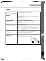
<Using the adjusters to adjust image position>
If you mount this unit on a tabletop, you can use the adjusters on its underside to change the
position of the projection image. Rotate the movable part of the two screw-type adjusters at
the front bottom of the case to adjust the height. The movement range of the adjusters is 3
cm (1-1/4 inch). Adjust with care as loosening them further than 3 cm may cause them to
separate from the unit.
Projection image position
◆ Keystone adjustment
If you mount the unit at an angle to the screen, it projects trapezoidally distorted images. You can use the [V keystone Correction] or [H
keystone Correction] item in the [Setup] menu group to rectify this. (☞ page 36)
Memo
• If the keystone is adjusted aspect ratio may not be correctly maintained. To correctly maintain the aspect ratio, try to use the DPX-
1300 with the lens shift in the center position.
• The video may be disturbed by keystone correction. Wherever possible, we recommend setting up so the screen and projector
form a right angle.
Wide Tele
Lens centerline
Lens centerline
(When shifted
fully up)
Lens centerline
(When shifted
fully down)
11_DPX-1300_E.p65 9/20/05, 4:00 PM14

15
Connection
7
English
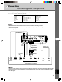
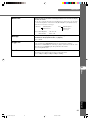
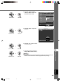
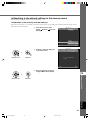
Connecting to AV components
This unit is equipped with 7 types of video input jacks for AV components. Follow the diagram to connect AV components to this unit, taking
care to use cables and adapters that match the input jacks.
Warning
• Be sure to turn off the power of this unit and the source component before attempting connection.
• Connection methods and jack names may differ depending on the component you are attempting to connect. Refer to the owner’s
manual for the component.
• Insert all plugs firmly to avoid noise or other problems.
Memo
• Be sure to connect Y/PB/PR and Y/CB/CR to the jacks with the correct signals when connecting AV components to INPUT A. Refer to
the owner’s manual of the source component for more information. You may need to make connections to HD/SYNC and VD for
RGB video signals.
D connector
cable
D-sub
monitor
cable
BNC cable for
component connection
Pin/BNC
adapters
Pin cable
Video pin cable
S-Video cable
D1—4
output
connectors
Pin jacksD-sub
Component/RGB video output connectors
Image output from AV components
BNC jacks S-Video output
jack
Video output
jack
HDMI cable (digital)
HDMI
output
connector
7 Connection
DVI cable (digital)
DVI output
connector
Input
VIDEO
S VIDEO
INPUT A
INPUT B
D4 VIDEO
HDMI
DVI
Signal type
Composite video
S-Video
Component video/RGB video
Component video/RGB video
Component video
Component video/RGB video (digital)
RGB video (digital)
Connector type
Pin jack
Mini DIN connector
BNC connector x 3-5
D-sub 15 pin
D connector
HDMI connector
DVI connector
HDMI
G/Y B/P
B
/C
B
R/P
R
/C
R
INPUT A
HD/SYNC
VD
OUT IN
REMOTE
TRIGGER OUT
S VIDEO VIDEO
INPUT B
RGB/YP
B
P
R
/YC
B
C
R
RS-232C
D4 VIDEO
DVI
G
/
YR
/
P
R
/
C
R
B
/
P
B
/
C
B
11_DPX-1300_E.p65 9/20/05, 4:00 PM15

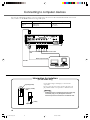
16
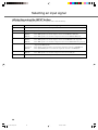
You can use the following three methods to connect to computer devices. Be sure to use cables with jacks that match the connectors and
jacks you wish to use. The HDMI terminal does not support PC signals.
Connecting to computer devices
HDMIDVI
G/Y B/P
B
/C
B
R/P
R
/C
R
INPUT A
HD/SYNC
VD
OUT IN
REMOTE
TRIGGER OUT
S VIDEO VIDEO
INPUT B
RGB/YP
B
P
R
/YC
B
C
R
RS-232C
D4 VIDEO
D-Sub monitor
cable
BNC monitor cable
Monitor output terminal
Computer devices
Use the supplied trigger-out DC plug to control external
components.
Be sure to solder the wires from an external component to the
plug terminals with the correct polarities, as illustrated at left.
Warning
• Soldering the wires to terminals with incorrect polarity may
cause bodily injury or may damage this unit and the
external component connected to this unit with this cable.
Information for installers
(for US model only)
+ polarity (inside)
- polarity (outside)
(GND)
+ polarity
- polarity
Input
INPUT A
INPUT B
DVI
Signal type
RGB (Analog)
RGB (Analog)
RGB (Digital)
Connector type
BNC jack x 5
D-sub 15 pin
DVI connector
DVI cable
11_DPX-1300_E.p65 9/20/05, 4:00 PM16
Sidan laddas...
Sidan laddas...
Sidan laddas...
Sidan laddas...
Sidan laddas...
Sidan laddas...
Sidan laddas...
Sidan laddas...
Sidan laddas...
Sidan laddas...
Sidan laddas...
Sidan laddas...
Sidan laddas...
Sidan laddas...
Sidan laddas...
Sidan laddas...
Sidan laddas...
Sidan laddas...
Sidan laddas...
Sidan laddas...
Sidan laddas...
Sidan laddas...
Sidan laddas...
Sidan laddas...
Sidan laddas...
Sidan laddas...
Sidan laddas...
Sidan laddas...
Sidan laddas...
Sidan laddas...
Sidan laddas...
Sidan laddas...
Sidan laddas...
Sidan laddas...
Sidan laddas...
Sidan laddas...
Sidan laddas...
Sidan laddas...
Sidan laddas...
Sidan laddas...
Sidan laddas...
Sidan laddas...
Sidan laddas...
Sidan laddas...
Sidan laddas...
Sidan laddas...
Sidan laddas...
Sidan laddas...
Sidan laddas...
Sidan laddas...
-
 1
1
-
 2
2
-
 3
3
-
 4
4
-
 5
5
-
 6
6
-
 7
7
-
 8
8
-
 9
9
-
 10
10
-
 11
11
-
 12
12
-
 13
13
-
 14
14
-
 15
15
-
 16
16
-
 17
17
-
 18
18
-
 19
19
-
 20
20
-
 21
21
-
 22
22
-
 23
23
-
 24
24
-
 25
25
-
 26
26
-
 27
27
-
 28
28
-
 29
29
-
 30
30
-
 31
31
-
 32
32
-
 33
33
-
 34
34
-
 35
35
-
 36
36
-
 37
37
-
 38
38
-
 39
39
-
 40
40
-
 41
41
-
 42
42
-
 43
43
-
 44
44
-
 45
45
-
 46
46
-
 47
47
-
 48
48
-
 49
49
-
 50
50
-
 51
51
-
 52
52
-
 53
53
-
 54
54
-
 55
55
-
 56
56
-
 57
57
-
 58
58
-
 59
59
-
 60
60
-
 61
61
-
 62
62
-
 63
63
-
 64
64
-
 65
65
-
 66
66
-
 67
67
-
 68
68
-
 69
69
-
 70
70


Yamaha DPX-1300 Användarmanual
- Kategori
- Dataprojektorer
- Typ
- Användarmanual
- Denna manual är också lämplig för
på andra språk
- italiano: Yamaha DPX-1300 Manuale utente
- čeština: Yamaha DPX-1300 Uživatelský manuál
- español: Yamaha DPX-1300 Manual de usuario
- Deutsch: Yamaha DPX-1300 Benutzerhandbuch
- polski: Yamaha DPX-1300 Instrukcja obsługi
- português: Yamaha DPX-1300 Manual do usuário
- français: Yamaha DPX-1300 Manuel utilisateur
- Türkçe: Yamaha DPX-1300 Kullanım kılavuzu
- English: Yamaha DPX-1300 User manual
- dansk: Yamaha DPX-1300 Brugermanual
- русский: Yamaha DPX-1300 Руководство пользователя
- suomi: Yamaha DPX-1300 Ohjekirja
- Nederlands: Yamaha DPX-1300 Handleiding
- română: Yamaha DPX-1300 Manual de utilizare
Relaterade papper
-
Yamaha DPX-1 Bruksanvisning
-
Yamaha DPX-1200 Bruksanvisning
-
-
-
-
-
-
-
-