
i-SERIES
ENERGIZER
REMOTE &
FAULT FINDER
Instructions
Installatie instucties
Notice d’installation
Betriebsanleitung
Monteringsvejledning
Instrucciones
Monteringsinstrucktioner
Istruzioni per l’installazione
- ENG
- NED
- FRA
- DEU
- DAN
- ESP
- SVE
- ITA

PUBLISHED BY
Gallagher Group Limited
181 Kahikatea Drive, Private Bag 3026
Hamilton, New Zealand
www.gallagher.com
Copyright© Gallagher Group Limited 2021
All rights reserved. Patents pending.
Gallagher i-Series Energizer Remote &
Fault Finder User Manual
3E2749 - Edi on 6 - June 2021
DISCLAIMER: Whilst every eff ort has
been made to ensure accuracy, neither
Gallagher Group Limited nor any employee
of the company shall be liable on any
ground whatsoever to any party in respect
of decisions or ac ons they may make as a
result of using this informa on.
In accordance with the Gallagher policy
of con nuing development, design and
specifi ca ons are subject to change
without no ce.
Developed and manufactured by Gallagher
Group Limited, and ISO 9001 2000
Cer fi ed Supplier.

Contents
English 5
Remote Readings ........................................................................ 5
Installing the baery ................................................................... 6
Features ...................................................................................... 7
Checking your fence and nding faults ....................................... 8
Detecng Alarms ......................................................................... 9
Turning the Energizer On / O (Standby) .................................. 10
Using your Remote with mulple Energizers ............................ 10
Adding a channel ...................................................................... 11
Understanding your Electric Fence ........................................... 12
Waste electrical and electronic equipment .............................. 13
Nederlands 14
Waarden aezen met de afstandsbediening ............................. 14
De baerij plaatsen ................................................................... 15
Funces ..................................................................................... 16
Uw afrastering controleren en storingen opsporen ..................17
Alarmmeldingen detecteren ..................................................... 18
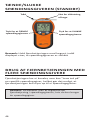
Schrikdraadapparaat in-/uitschakelen (stand-by) ..................... 19
Uw afstandsbediening met meerdere schrikdraadapparaten
gebruiken ............................................................................... 19
Een kanaal toevoegen .............................................................. 20
Hoe werkt uw elektrische Afrastering? ..................................... 21
Afgedankte elektrische en elektronische apparatuur ............... 22
Français 23
Achages de la télécommande ................................................ 23
Installaon de la pile ................................................................. 24
Caractérisques ........................................................................ 25
Véricaon de la clôture et recherche des pertes .................... 26
Détecon des alarmes .............................................................. 27
Acvaon/désacvaon de l’électricateur (mode veille) ....... 28
Ulisaon de la télécommande avec plusieurs électricateurs 28
Ajout d’un canal ........................................................................ 29
Comment fonconne votre cloture electrique .........................30
Déchets d’équipements électriques et électroniques ...............31
Deutsch 32
Fernabfrage ............................................................................. 32
Installaon der Baerie .......................................................... 33
Eigenschaen .......................................................................... 34
Wie Sie Ihren Zaun überprüfen und Fehler aufspüren ............ 35
Alarme aufspüren .................................................................... 36
Elektrozaungerät auf EIN / AUS (Standby) schalten ................ 37
Benutzung des Fernabfragegeräts mit mehreren
Elektrozaungeräten ............................................................... 37
Kanal hinzufügen ..................................................................... 38
Verstehen Sie Ihren Elektrozaun? ............................................ 39

4
Elektrische und elektronische Abfallprodukte ......................... 40
Dansk 41
Udlæsninger på ernbetjening ................................................ 41
Isætning af baeriet ................................................................ 42
Funkoner ............................................................................... 43
Kontrol af hegnet og fejlsøgning .............................................. 44
Detektering af alarmer ............................................................ 45
Tænde/slukke spændingsgiveren (standby) ............................46
Brug af ernbetjeningen med ere spændingsgivere .............46
Sådan lføjes en kanal ............................................................. 47
Forstå dit elhegn ...................................................................... 48
Aald af elektrisk og elektronisk udstyr .................................. 49
Español 50
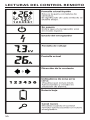
Lecturas del control remoto .................................................... 50
Instalación de la batería .......................................................... 51
Caracteríscas.......................................................................... 52
Revisando su cerca y encontrando los fallos ........................... 53
Detectando alarmas ................................................................ 54
Encendiendo/ apagando el Energizador (En espera) ............... 55
Ulización de su control remoto con varios Energizadores ..... 55
Añadir canales ......................................................................... 56
Comprendiendo su cerca eléctrica .......................................... 57
Eliminación de equipo eléctrico y electrónico .........................58
Svenska 59
Fjärravläsningar ....................................................................... 59
Montera baeriet .................................................................... 60
Funkoner ............................................................................... 61
Kontrollera stängslet och hia fel ........ .................................... 62
Upptäcka larm ......................................................................... 63
Slå på/stänga av aggregatet (standby) ..................................... 64
Använda ärrkontrollen med era aggregat ............................64
Lägga ll en kanal .................................................................... 65
Förstå di elstängsel ................................................................ 66
Avfall - elektrisk och elektronisk utrustning ............................67
Italiano 68
Signicato dei simboli .............................................................. 68
Installare la baeria ................................................................. 69
Caraerische ......................................................................... 70
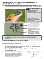
Verica della recinzione e ricerca guas ..................................71
Rilevazione degli allarmi .......................................................... 72
Accendere o spegnere (standby) l’elericatore ..................... 73
Uso del telecomando con più elericatori ............................ 73
Aggiunta di un elericatore ................................................... 74
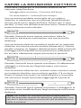
Capire la recinzione elerica ................................................... 75
Roamazione arezzature Eleriche od Eleroniche ............. 76
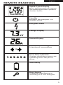
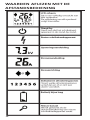
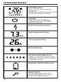
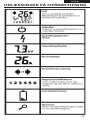
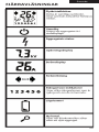
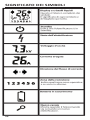
This is the full range of symbols.
The meaning of each symbol is
detailed below.
Liquid Crystal Display
Standby
Indicates the energizer is in
Standby mode.
Energizer status
Current Display
Direction of current ow
Voltage Display
Fence Zone indicators
Displays which fence zones are
operating and if they are in
alarm.
Low battery
Remote readings
123456
OR
123456
New channel
Displayed when Remote is
searching for a new energizer.

4 5
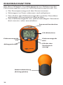
This is the full range of symbols.
The meaning of each symbol is
detailed below.
Liquid Crystal Display
Standby
Indicates the energizer is in
Standby mode.
Energizer status
Current Display
Direction of current ow
Voltage Display
Fence Zone indicators
Displays which fence zones are
operating and if they are in
alarm.
Low battery
Remote readings
123456
OR
123456
New channel
Displayed when Remote is
searching for a new energizer.
REMOTE READINGS English

6
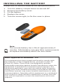
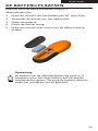
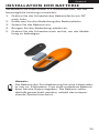
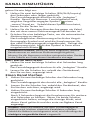
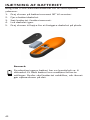
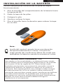
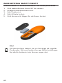
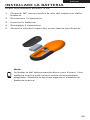
INSTALLING THE BATTERY
Always use 9V alkaline baeries for best performance.
1. Turn the baery compartment screw le 90o.
2. Remove the baery cover.
3. Fit the baery.
4. Replace the cover.
5. Turn the screw right, to x the cover in place.
Note:
The remote baery has a life of approximately 6
months. A at baery may give false measurements
so replace the baery when the icon shows.
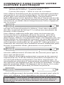
Note: Approvals & Standards - FCC
This equipment has been tested and found to comply with
the limits for a Class A digital device, pursuant to part 15
of the FCC Rules. These limits are designed to provide
reasonable protecon against harmful interference when the
equipment is operated in a commercial environment. This
equipment generates, uses and can radiate radio frequency
energy and, if not installed and used in accordance with the
instrucon manual, may cause harmful interference to radio
communicaons. Operaon of this equipment in a residenal
area is likely to cause harmful interference in which case the
user will be required to correct the interference at his own
expense.

6 7
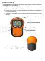
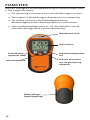
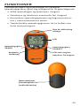
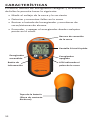
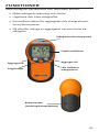
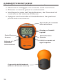
FEATURES
The Gallagher Energizer Remote and Fault Finder enables
you to do the following:
• Measure fence voltage and current
• Detect and nd fence faults
• Check the status of the energizer and fence monitors
/ alarm systems.
• Turn the energizer on or o from any locaon on the
fence.
Liquid Crystal Display
Energizer ON Energizer OFF
Inquire
(Grounding contact plate)
fence pulse

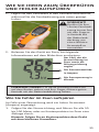
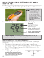
8
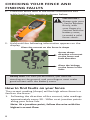
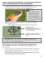
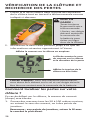
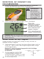
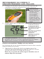
CHECKING YOUR FENCE AND
FINDING FAULTS
1. Place the fence wire in the fence connecons slot
while holding the remote as shown below.
2. Hold unl the following informaon appears on the
display.
Handy Hint: For best performance, you must be
standing on the ground, and your ngers must make
good contact with the baery cover.
Gives the current on the fence in Amps
Arrow shows
on the fence and
Gives the Voltage
on the fence in kilo
Volts
The current reading (Amps) will be high when there is a
fault on the fence.
1. Following the direcon of the current, take readings
approximately every 50 - 100m or at juncon points
along your fence line.
IMPORTANT:
Always grip your
i-Series Remote
rmly, with
your ngers in
contact with the
baery cover,
to avoid a mild
fence shock.
!

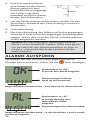
8 9
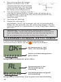
2. A fault is indicated by
a drop in current ow
between two check-
points. The fault will be
somewhere between the
two checkpoints.
3. To narrow down locaon of the fault, work back
along the fence checking the current ow at shorter
intervals.
4. Correct the fault.
5. Aer correcng the fault you should see the current
reading drop and the voltage go up. If not, check for
further faults.
Note: Mulwire fences connected in parallel will have
similar current owing in each wire. To get the total
fence current ow, add together the current ow in
each wire.
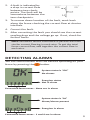
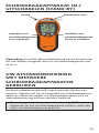
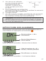
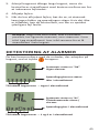
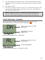
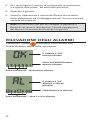
DETECTING ALARMS
You can communicate with the devices operang on your
fence by pressing the buon.
System status is “OK”
No alarms
Energizer status
Not in alarm
Connected fence zones - None are in alarm
Energizer in alarm
Connected fence zones - 1 and 4 are in alarm
System status is “AL”
Alarm/alarms present

10
The Remote has nine channels that can be “tuned in” to
a specic energizer, enabling the Remote to control up to
nine energizers.
USING YOUR REMOTE WITH
MULTIPLE ENERGIZERS
Note: You do NOT need to register your Remote with the
Energizer if you are only using one Energizer.
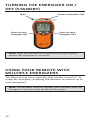
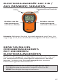
TURNING THE ENERGIZER ON /
Wire
Press to turn
Energizer ON
Press to turn
Energizer OFF
Note: Hold the Remote on the fence unl the display
shows the energizer is on or o.

10 11
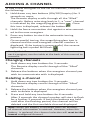
ADDING A CHANNEL
Changing channels
1. Hold down any two buons for 3 seconds.
The Remote display scrolls through all the “lled”
channels.
2. Release the buons when the energizer channel you
wish to communicate with is displayed.
To add a new energizer to the list of channels, complete
the following:
1. Hold down any two buons (ON/OFF/Inquiry) for 3
seconds or more.
The Remote display scrolls through all the “lled”
channels. Before returning back to 1, a “new” channel
is indicated by the magnifying glass icon . Once
this icon is displayed, release the buon.
2. Hold the fence connecon slot against a wire connect-
ed to the new energizer.
3. Press any buon to start the automac tuning
process.
On successful tuning, the magnifying glass icon is
cleared and the new energizer channel number is
displayed. If the tuning is unsuccessful, the reverse
lightning bolt symbol will ash.
1. Hold down any two buons for 3 seconds.
The Remote display scrolls through all the “lled”
channels.
2. Release the buons when the energizer channel you
wish to delete is displayed.
3. Press and hold any two buons for 6 seconds.
Aer 3 seconds the channel number will start to ash
for a further 3 seconds. If both the buons are held
unl aer the ashing period, the channel will be
deleted and the rst available channel displayed.
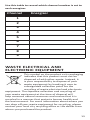
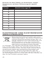
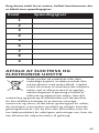
Handy Hint: To remember which channel number is set to
each energizer, use the table at the back of this manual to
record it.
Note: When the baery is removed from the Remote,
all channel informaon is retained. However, when the
baery is replaced, the channel selecon will reset to the
lowest congured channel.

12
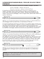
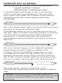
Compare your electric fence to a water supply system.
Fence Voltage = Water Pressure
Electric Current = Water Volume/Flow
A perfectly performing Electric fence is similar to a
water system that has a pressure pump (Energizer) at
one end and a bung at the other. There would be high
water pressure (voltage) and a high ow potenal with no
water leaking.
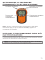
UNDERSTANDING YOUR ELECTRIC
FENCE
When an animal touches this fence there is total delivery
of voltage and current for a maximum shock.
A normal electric fence is similar to a water pipe with one
or two leaks (faults). While a minor ow of water (current)
will ow into these leaks and reduce overall pressure
(voltage) at point B, the pressure is sll signicant enough
to deliver enough water (current) at point B as needed.
When an animal touches the fence, there is sll sucient
voltage and current to deliver an eecve shock.
An electric fence with a substanal fault on the fence line
is similar to a water system with a major leak. Hence you
will see signicant ow of water (current) along the pipe
to this leak. As most of the water is owing out of this
leak very lile water (current) reaches point B.
When an animal touches the fence at point B, there is
insucient voltage and current to deliver an eecve
shock.
Note: To avoid excessive baery use caused by accidental
acvaon, do not leave your Remote on or near the
energizer or electric fence.

12 13
Channel Energizer
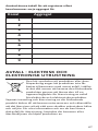
1
2
3
4
5
6
7
8
9
Use this table to record which channel number is set to
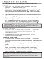
WASTE ELECTRICAL AND
ELECTRONIC EQUIPMENT
This symbol on the product or its packaging
indicates that this product must not be
disposed of with other waste. Instead, it
is your responsibility to dispose of your
waste equipment by handing it over to
a designated collecon point for the
recycling of waste electrical and electronic
equipment. The separate collecon and recycling of
your waste equipment at the me of disposal will
help conserve natural resources and ensure that it is
recycled in a manner that protects human health and
the environment. For more informaon about where you
can drop o your waste equipment for recycling, please
contact your local city recycling oce or the dealer from
whom you purchased the product.

14
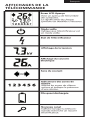
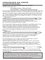
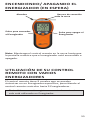
WAARDEN AFLEZEN MET DE
AFSTANDSBEDIENING

14 15
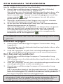
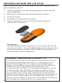
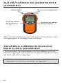
DE BATTERIJ PLAATSEN
Gebruik voor de beste prestaes aljd 9 V
alkalinebaerijen.
1. Draai de schroef van het baerijvak 90° naar links.
2. Verwijder de deksel van het baerijvak.
3. Plaats de baerij.
4. Plaats de deksel terug.
5. Draai de schroef naar rechts om de deksel vast te
maken.
Opmerking:
de baerij van de afstandsbediening gaat ca. 6
maanden mee. Een lege baerij kan verkeerde
meetwaarden geven. Vervang de baerij daarom
zodra het pictogram wordt getoond.
Nederlands

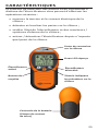
16
FUNCTIES
Met de Gallagher afstandsbediening en foutenvinder kunt
u het volgende doen:
• De spanning en stroom van uw afrasteringen meten.
• Storingen in afrasteringen detecteren en opsporen.
• De status van het schrikdraadapparaat en
afrasteringsmonitor/alarmsystemen controleren.
• Het schrikdraadapparaat in- of uitschakelen vanaf
een willekeurige plek op uw afrastering.
Draadmeet sleuf
LCD-scherm
Schrikdraad-
apparaat AAN
Schrikdraadapparaat
UIT
(Aardingsplaat)
LED die de pulsen
van de afrastering

16 17
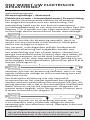
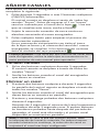
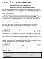
UW AFRASTERING CONTROLEREN
EN STORINGEN OPSPOREN
1. Plaats de draad van de afrastering in de
draadmeetsleuf terwijl u de afstandsbediening
vasthoudt zoals hieronder weergegeven.
2. Wacht tot de volgende informae op het display
wordt getoond.
Toont de stroom op de afrastering in ampère (A)
Pijl toont de
van de storing
Toont de spanning op
de afrastering in kilovolt
(kV)
De stroomwaarde (A) is hoog bij een storing op uw
afrastering.
1. Voer, met de richng van de stroom mee, om de 50
tot 100 meter een meng uit of op elk verbindings-
punt langs uw afrastering.
Opmerking: volg bij een verbindingspunt de draad
Storingen op uw afrastering opsporen
Voor de beste prestaes moet u op
de grond staan en moeten uw vingers goed contact
maken met het baerijklepje.
LET OP:
Houd uw i-Series-
afstandsbediening
aljd stevig vast,
terwijl uw vingers
contact maken met
het baerijklepje
om een lichte schok
van de afrastering te
voorkomen.
!

18
2. Een storing wordt aange-
geven met een val in de
stroomsterkte tussen twee
controlepunten. De storing
bevindt zich ergens tussen
de twee controlepunten.
3. Om de exacte locae van de
storing te achterhalen, loopt u de afrastering in
omgekeerde richng af om de stroomsterkte op
kortere intervallen te
controleren.
4. Verhelp de storing.
5. Nadat de storing is
verholpen, ziet u de waarde van de stroomsterkte
dalen en de waarde van de spanning sjgen. Als dit
niet het geval is, controleert u of er nog meer storin-
gen zijn.
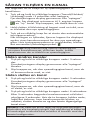
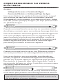
ALARMMELDINGEN DETECTEREN
U kunt met de apparaten op uw afrastering
communiceren door op de knop te drukken.
Systeemstatus is “OK”
Geen alarmmeldingen
Status schrikdraadapparaat:
geen alarm
Aangesloten rasterzones: geen alarm
alarmmelding
Aangesloten rasterzones: 1 en 4 geven een alarmmelding
Systeemstatus is “AL”
Alarmmelding(en)
aanwezig
Opmerking: bij meerdraadse, parallel geschakelde
afrasteringen hee elke draad dezelfde stroomsterkte.
Voor de totale stroomsterkte van de afrastering telt u
de stroomsterkte van alle draden bij elkaar op.

18 19
De afstandsbediening hee negen kanalen die kunnen
worden ‘afgestemd’ op één bepaald schrikdraadapparaat,
zodat er maximaal negen schrikdraadapparaten met de
afstandsbediening kunnen worden bediend.
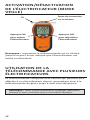
UW AFSTANDSBEDIENING
MET MEERDERE
SCHRIKDRAADAPPARATEN
GEBRUIKEN
Opmerking: U hoe uw afstandsbediening NIET te
registeren op het schrikdraadapparaat indien u maar één
enkel schrikdraadapparaat gebruikt.
Draadmeet sleuf
Draad
Indrukken om
schrikdraadapparaat
in te schakelen
Indrukken om
schrikdraadapparaat
uit uit te schakelen
Opmerking: houd de afstandsbediening op de afrastering
tot het display aangee dat het schrikdraadapparaat aan
of uit is.

20
Kanalen wijzigen
1. Houd twee willekeurige knoppen 3 seconden lang
ingedrukt.
Het display van de afstandsbediening bladert door alle
‘bezee’ kanalen.
2. Laat de knoppen los als het schrikdraadapparaatka-
naal wordt getoond waarmee u wilt communiceren.
EEN KANAAL TOEVOEGEN
Ga als volgt te werk om een nieuw schrikdraadapparaat
toe te voegen aan de lijst met kanalen:
1. Houd twee willekeurige knoppen (AAN/UIT/Info)
minimaal 3 seconden lang ingedrukt.
Het display van de afstandsbediening bladert door alle
‘bezee’ kanalen. Voordat het display naar 1 terug-
keert, wordt een ‘nieuw’ kanaal aangegeven met het
vergrootglas . Laat de knoppen los als dit picto-
gram wordt getoond.
2. Houd de draadmeet sleuf tegen een op het nieuwe
schrikdraadapparaat aangesloten draad.
3. Druk op een willekeurige knop om het automasche
afstemmingsproces te starten.
Als het afstemmen is voltooid, verdwijnt het vergroot-
glas en wordt het kanaalnummer van het nieuwe
schrikdraadapparaat getoond. Als het afstemmen
is mislukt, begint het symbool van de omgekeerde
bliksemschicht te knipperen .
Een kanaal verwijderen
1. Houd twee willekeurige knoppen 3 seconden lang
ingedrukt.
Het display van de afstandsbediening bladert door alle
‘bezee’ kanalen.
2. Laat de knoppen los als het schrikdraadapparaatkanaal
wordt getoond dat u wilt verwijderen.
3. Houd twee willekeurige knoppen 6 seconden lang
ingedrukt.
Na 3 seconden begint het kanaalnummer 3 seconden
lang te knipperen. Als beide knoppen worden ingedrukt
tot na het knipperen, wordt het kanaal verwijderd en
het eerst beschikbare kanaal getoond.
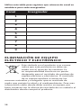
noteer in de tabel achterin deze handleiding
het kanaalnummer dat voor elk schrikdraadapparaat wordt
gebruikt.
Opmerking: als de baerij uit de afstandsbediening wordt
verwijderd, blij alle kanaalinformae behouden. Bij het
terugplaatsen van de baerij wordt de kanaalselece
echter gereset op het laagst gecongureerde kanaal.
Sidan laddas...
Sidan laddas...
Sidan laddas...
Sidan laddas...
Sidan laddas...
Sidan laddas...
Sidan laddas...
Sidan laddas...
Sidan laddas...
Sidan laddas...
Sidan laddas...
Sidan laddas...
Sidan laddas...
Sidan laddas...
Sidan laddas...
Sidan laddas...
Sidan laddas...
Sidan laddas...
Sidan laddas...
Sidan laddas...
Sidan laddas...
Sidan laddas...
Sidan laddas...
Sidan laddas...
Sidan laddas...
Sidan laddas...
Sidan laddas...
Sidan laddas...
Sidan laddas...
Sidan laddas...
Sidan laddas...
Sidan laddas...
Sidan laddas...
Sidan laddas...
Sidan laddas...
Sidan laddas...
Sidan laddas...
Sidan laddas...
Sidan laddas...
Sidan laddas...
Sidan laddas...
Sidan laddas...
Sidan laddas...
Sidan laddas...
Sidan laddas...
Sidan laddas...
Sidan laddas...
Sidan laddas...
Sidan laddas...
Sidan laddas...
Sidan laddas...
Sidan laddas...
Sidan laddas...
Sidan laddas...
Sidan laddas...
Sidan laddas...
-
 1
1
-
 2
2
-
 3
3
-
 4
4
-
 5
5
-
 6
6
-
 7
7
-
 8
8
-
 9
9
-
 10
10
-
 11
11
-
 12
12
-
 13
13
-
 14
14
-
 15
15
-
 16
16
-
 17
17
-
 18
18
-
 19
19
-
 20
20
-
 21
21
-
 22
22
-
 23
23
-
 24
24
-
 25
25
-
 26
26
-
 27
27
-
 28
28
-
 29
29
-
 30
30
-
 31
31
-
 32
32
-
 33
33
-
 34
34
-
 35
35
-
 36
36
-
 37
37
-
 38
38
-
 39
39
-
 40
40
-
 41
41
-
 42
42
-
 43
43
-
 44
44
-
 45
45
-
 46
46
-
 47
47
-
 48
48
-
 49
49
-
 50
50
-
 51
51
-
 52
52
-
 53
53
-
 54
54
-
 55
55
-
 56
56
-
 57
57
-
 58
58
-
 59
59
-
 60
60
-
 61
61
-
 62
62
-
 63
63
-
 64
64
-
 65
65
-
 66
66
-
 67
67
-
 68
68
-
 69
69
-
 70
70
-
 71
71
-
 72
72
-
 73
73
-
 74
74
-
 75
75
-
 76
76


på andra språk
- italiano: Gallagher G50700 Istruzioni per l'uso
- español: Gallagher G50700 Instrucciones de operación
- Deutsch: Gallagher G50700 Bedienungsanleitung
- français: Gallagher G50700 Mode d'emploi
- English: Gallagher G50700 Operating instructions
- dansk: Gallagher G50700 Betjeningsvejledning
- Nederlands: Gallagher G50700 Handleiding


