Rotel A14 Bruksanvisning
- Kategori
- Kompletterande musikutrustning
- Typ
- Bruksanvisning

A14
Stereo Integrated Amplier
Amplicateur Stéréo Intégré
Stereo-Vollverstärker
Amplicador Integrado Estereofónico
Geïntegreerde stereoversterker
Amplicatore integrato stereo
Integrerad stereoförstärkare
Интегрированный стерео усилитель
Owner’s Manual
Manuel de l’utilisateur
Bedienungsanleitung
Manual de Instrucciones
Gebruikershandleiding
Manuale di istruzioni
Instruktionsbok
Инструкция пользователя

2
A14 Stereo Integrated Amplier
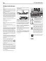
You must allow a minimum 10 cm or 4 inches of unobstructed
clearance around the unit.
WARNING: The rear panel power cord connector is the mains power
disconnect device. The device must be located in an open area that
allows access to the cord connector.
The unit must be connected to a power supply only of the type and
voltage specified on the rear panel. (USA: 120 V/60Hz, EC: 230V/50Hz)
Connect the component to the power outlet only with the supplied
power supply cable or an exact equivalent. Do not modify the supplied
cable. Do not use extension cords.
The mains plug is the disconnect of the unit. In order to completely
disconnect the unit from the supply mains, remove the main plug from
the unit and the AC power outlet. This is the only way to completely
remove mains power from the unit.
Use Class 2 wiring for speaker connections to ensure proper installation
and minimize the risk of electrical shock.
The batteries in the remote control should not be exposed to excessive
temperature such as sunshine, re or other heat sources. Batteries
should be recycled or disposed as per state and local guidelines.
Notice
The RS232 connection should be handled by authorized persons only.
WARNING: There are no user serviceable parts inside. Refer all
servicing to qualified service personnel.
WARNING: To reduce the risk of fire or electric shock, do not expose
the unit to moisture or water. Do not expose the unit to dripping or
splashing. Do not place objects filled with liquids, such as vases, on
the unit. Do not allow foreign objects to get into the enclosure. If the
unit is exposed to moisture, or a foreign object gets into the enclosure,
immediately disconnect the power cord from the wall. Take the unit
to a qualified service person for inspection and necessary repairs.
Read these instructions.
Keep these instructions.
Heed all warnings.
Follow all instructions.
Do not use this apparatus near water.
Clean only with dry cloth.
Do not block any ventilation openings. Install in accordance with the
manufacturer’s instructions.
Do not install near any heat sources such as radiators, heat registers,
stoves, or other apparatus (including amplifiers) that produce heat.
Do not defeat the safety purpose of the polarized or grounding-type
plug. A polarized plug has two blades with one wider than the other.
A grounding type plug has two blades and a third grounding prong.
The wide blade or the third prong are provided for your safety. If
the provided plug does not fit into your outlet, consult an electrician
for replacement of the obsolete outlet.
Protect the power cord from being walked on or pinched particularly
at plugs, convenience receptacles, and the point where they exit
from the apparatus.
Only use attachments/accessories specified by the manufacturer.
Use only with the cart, stand, tripod, bracket, or
table specified by the manufacturer, or sold with
the apparatus. When a cart is used, use with caution
when moving the cart/apparatus combination to
avoid injury from tip-over.
Unplug this apparatus during lightning storms or when unused for
long periods of time.
Refer all servicing to qualified service personnel. Servicing is required
when the apparatus has been damaged in any way, such as power-
supply cord or plug is damaged, liquid has been spilled or objects
have fallen into the apparatus, the apparatus has been exposed to
rain or moisture, does not operate normally, or has been dropped.
The apparatus should be used in non tropical climate.
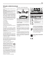
Rotel products are designed to comply with
international directives on the Restriction of Hazardous
Substances (RoHS) in electrical and electronic
equipment and the disposal of Waste Electrical and
Electronic Equipment (WEEE). The crossed wheelie bin
symbol indicates compliance and that the products must
be appropriately recycled or processed in accordance
with these directives.
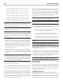
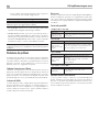
Important Safety Instructions
POWER
PHONES
A12
PHONO TUNER CD USB OPT COAX AUX PC-USB BT
5V / 2.1A
MENU
SPEAKERS
A B
POWER
PHONES
A14
PHONO TUNER CD USB OPT COAX AUX PC-USB BT
5V
/
2.1A
MENU
SPEAKERS
A B
This symbol means that this unit is double insulated.
An earth connection is not required.

3
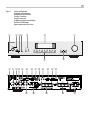
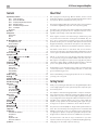
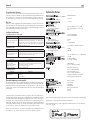
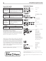
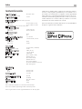
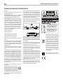
Figure 1: Controls and Connections
Commandes et Branchements
Bedienelemente und Anschlüsse
Controles y Conexiones
Controlli e connessioni
De bedieningsorganen en aansluitingen
Kontroller och anslutningar
Органы управления и разъемы
POWER
PHONES
A 14
PHONO TUNER CD USB OPT COAX AUX PC-USB BT
5V / 2.1A
MENU
SPEAKERS
A B
0 - =
q w
e r
t
y
u
i o
[
] \
a s
1
2 3
4
5
6
7
8
9
p

4
A14 Stereo Integrated Amplier
A
B
C
D
E
F
G
H
I
N
L
K
J
M
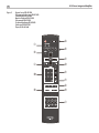
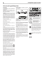
Figure 2: Remote Control RR-AX1400
Télécommande infra-rouge RR-AX1400
Fernbedienung RR-AX1400
Mando a Distancia RR-AX1400
Telecomando RR-AX1400
De afstandsbediening RR-AX1400
Fjärrkontroll RR-AX1400
Пульт ДУ RR-AX1400

5
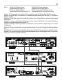
Figure 3: Preamp Input and Speaker Output Connections
Branchements des entrées sources et sorties enceintes acoustiques
Anschlussdiagramm
Conexiones para Entrada de Señal y Salida a las Cajas Acústicas
Collegamenti ingressi e diffusori
De signaalingangen en de luidsprekeruitgangen
Signal- och högtalaranslutningar
Подсоединение источников сигнала и акустических систем
Amplifier A14
CD PLAYER
PHONO

6
A14 Stereo Integrated Amplier
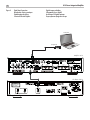
Figure 4: Digital Input Connections
Branchements Entrées numériques
Digitaleingänge-Anschlüsse
Conexiones Entradas Digitales
Digitale ingang verbinding
Collegamenti ingressi digitali
Anslutningar för digitala ingångar
Подсоединение Цифровые входы
Computer
CLASS 1
LASER PRODUCT
APPAREIL LASER
DE CLASSE 1
MODEL NO.: CD14
RP-572C
Amplier A14
(Supplied)
CD Player CD14

7
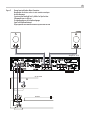
Figure 5: Rotel Link and 12V Trigger Connections
Branchements Rotel Link et trigger 12 V
Rotel Link- und 12V-Trigger-Anschlüsse
Conexiones Rotel Link y para Señal de Disparo de 12V
CLASS 1
LASER PRODUCT
APPAREIL LASER
DE CLASSE 1
MODEL NO.: CD14
RP-572C
CD Player CD14
Amplifier A14
T14
NETWORK TUNER
R
ANTENNA
FM
DAB
L
OUTPUT
COAXIAL OUT
USB
RS232
12V TRIGGER
IN OUTOUT
ROTEL LINK
OUT
RP-571B
Tuner T14
WIFI ANTENNA
WIFI ANTENNA
Important! : The 12V trigger cables will override the Rotel Link commands. Do not connect the 12V trigger cable if Rotel Link is connected.
Important : Les connexions trigger 12v sont prioritaires sur les commandes Rotel Link. Ne branchez pas de câble trigger 12 V si une connexion
Rotel Link a été réalisée.
Wichtig! Die 12V-Trigger-Kabel umgehen die Rotel Link-Befehle. Schließen Sie kein 12V-Trigger-Kabel an, wenn die Rotel Link-Verbindung
hergestellt wurde.
¡Importante!: Los cables para señal de disparo de 12V bloquearán las órdenes de control vía Rotel Link. Por lo tanto, cuando el Rotel Link esté
conectado no conecte ningún cable para señal de disparo de 12V.
Importante! I segnali Trigger 12 V hanno la precedenza sui comandi Rotel Link, pertanto non effettuare i collegamenti Trigger 12 V se si utilizza
il bus Rotel Link.
Belangrijk: De 12V trigger aansluitingen hebben voorrang op de Rotel Link opdrachten. Sluit dus niet de 12V triggerkabel en Rotel Link tegelijkertijd
aan.
Viktigt! Kablarna för 12 V styrsignaler åsidosätter Rotel Link-kommandon. Anslut inte kablar för 12 V styrsignal om det nns en Rotel Link-anslutning.
Внимание! : 12-В триггерный сигнал имеет приоритет над командами шины Rotel Link. Не подсоединяйте кабель 12-В триггерного
сигнала, если уже сделано соединение по Rotel Link.
De Rotel Link en 12V trigger aansluitingen
Collegamenti Rotel Link e segnali Trigger 12 V
Rotel Link-anslutning och 12 V-anslutning för styrsignal
Подсоединение Rotel Link и 12-В триггерного сигнала

8
A14 Stereo Integrated Amplier
POWER
PHONES
A 14
PHONO TUNER CD USB OPT COAX AUX PC-USB BT
5V
/
2.1A
MENU
SPEAKERS
A B
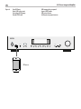
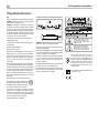
iPhone
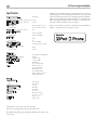
Figure 6: Front USB Input
Entrée USB en face avant
Frontseitiger USB-Eingang
Entrada USB Frontal
USB-ingang op het voorpaneel
Ingresso USB frontale
USB-port på fronten
USB вход на передней панели

9
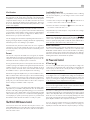
Important Notes
When making connections be sure to:
Turn off all the components in the system before hooking up any components, including loudspeakers.
4 Turn off all components in the system before changing any of the connections to the system.
It is also recommended that you:
4 Turn the volume control of the amplifier all the way down before the amplifier is turned on or off.
Remarques importantes
Pendant les branchements, assurez-vous que :
Tous les maillons sont éteints avant leur branchement, quels qu’ils soient, y compris les enceintes acoustiques.
4 Éteignez tous les maillons avant de modifier quoi que ce soit au niveau de leurs branchements, quels qu’ils soient.
Il est également recommandé de :
4 Toujours baissez le niveau sonore via le contrôle de volume, avant d’allumer ou d’éteindre l’amplificateur.
Wichtige Hinweise
Achten Sie beim Herstellen der Verbindungen auf Folgendes:
4 Schalten Sie alle Komponenten im System ab, bevor Sie Geräte (einschließlich Lautsprecher) anschließen.
4 Schalten Sie alle Komponenten im System ab, bevor Sie Anschlüsse im System verändern.
Ferner empfehlen wir, dass
4 Sie die Lautstärke herunterdrehen, bevor Sie die Endstufe ein- oder abschalten.
Notas Importantes
Cuando realice las conexiones, asegúrese de que:
4 Desactiva todos los componentes del equipo, cajas acústicas incluidas, antes de conectar cualquier nuevo componente en el mismo.
Desactiva todos los componentes del equipo antes de cambiar cualquier conexión del mismo.
También le recomendamos que:
Reduzca el nivel de volumen de su amplificador a cero antes de activarlo o desactivarlo.
Héél belangrijk
Bij het maken van de verbindingen:
Zorg dat niet alleen de A14, maar de gehele installatie uitstaat, als nog niet alle verbindingen gemaakt zijn.
Zorg dat niet alleen de A14, maar de gehele installatie ook uitstaat, als u verbindingen gaat wijzigen.
Wij raden u ook aan om
de volumeregelaar van de voorversterker geheel dicht te draaien (volkomen naar links) wanneer u uw eindversterker aan- of uitzet.
Note importanti
Quando effettuate i collegamenti assicuratevi di:
Spegnere tutti i componenti del sistema prima di collegare qualsiasi componente, inclusi i diffusori.
Spegnere tutti i componenti del sistema prima di modificare qualsiasi connessione nel sistema.
Vi raccomandiamo inoltre di:
Portare il volume a zero prima di accendere o spegnere l’amplificatore.
Viktigt
Tänk på följande när du gör anslutningar:
4 Stäng av alla apparater i anläggningen innan du ansluter nya komponenter eller högtalare.
4 Stäng av alla apparater i anläggningen innan du ändrar någon anslutning.
Du rekommenderas också:
Vrid ner volymen på förförstärkaren helt och hållet innan förstärkaren slås på eller av.
Важные замечания
Перед подсоединением:
4 Выключите все компоненты, включая колонки.
Выключите все компоненты в вашей системе, прежде чем что-то в ней менять.
Рекомендуется также:
Вывести громкость усилителя на минимум, перед тем как включать или выключать его.

10
A14 Stereo Integrated Amplier
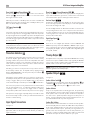
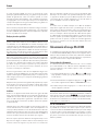
About Rotel
Our story began over 50 years ago. Over the decades, we have received
hundreds of awards for our products and satised hundreds of thousands
of people who take their entertainment seriously – like you.
Rotel was founded by a family whose passionate interest in music led them
to manufacture high-delity components of uncompromising quality.
Through the years, that passion has remained undiminished and the family
goal of providing exceptional value for audiophiles and music lovers,
regardless of their budget, is shared by all Rotel employees.
Rotel’s engineers work as a close team, listening to, and ne tuning, each
new product until it reaches their exacting musical standards. They are
free to choose components from around the world in order to make that
product the best they can. You are likely to nd capacitors from the United
Kingdom and Germany, semiconductors from Japan or the United States,
while toroidal power transformers are manufactured in Rotel’s own factory.
We all have concerns about our environment. And, as more and more
electronics are produced it is especially important for a manufacturer to do all
it can to engineer products that have a minimum impact on the environment.
At Rotel, we are proud to do our part. We have reduced the lead content
in our products by using special lead-free ROHS solder and components.
Our engineers continually strive to improve power supply efciency without
compromise to quality. When in standby mode Rotel products use minimal
power to meet global Standby Power Consumption requirements.
The Rotel factory is also doing their part to help the environment through
constant improvements to product assembly methods for a cleaner and
greener manufacturing processes.
All of us at Rotel thank you for buying this product. We are sure it will bring
you many years of enjoyment.
Getting Started
Thank you for purchasing the Rotel A14 Stereo Integrated Amplier. When
used in a high-quality music audio system, Rotel products will provide years
of musical enjoyment.
This amplier is a full featured, high performance component. All aspects
of the design have been optimized to retain the full dynamic range and
subtle nuances of your music. The unit has a highly regulated power supply
incorporating a Rotel custom-designed toroidal power transformer. This low
impedance power supply has ample power reserves, which enables the
amplier to easily reproduce the most demanding audio signals. This type
of design is more expensive to manufacture, but it is better for the music.
The printed circuit boards (PCB) are designed with Symmetrical Circuit
Traces. This ensures that the precise timing of the music is maintained and
faithfully recreated. The circuitry uses metal lm resistors and polystyrene
or polypropylene capacitors in important signal paths. All aspects of this
design have been examined to ensure the most faithful music reproduction.
The main functions of the A14 are easy to install and use. If you have
experience with other stereo systems, you shouldn’t nd anything perplexing.
Simply plug in the associated components and enjoy.
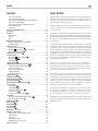
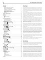
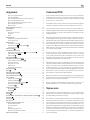
Contents
Important Safety Instructions ..........................................2
Figure 1: Controls and Connections 3
Figure 2: Remote Control RR-AX1400 4
Figure 3: Preamp Input and Speaker Output Connections 5
Figure 4: Digital Input Connections 6
Figure 5: Rotel Link and 12V Trigger Connections 7
Figure 6: Front USB Input 8
Important Notes 9
About Rotel ......................................................10
Getting Started ...................................................10
A Few Precautions 11
Placement 11
Cables 11
The RR-AX1400 Remote Control .......................................11
Second Amplier Remote Code 11
Remote Control Batteries 11
AC Power and Control ..............................................11
AC Power Input
s
11
Power Switch
1
A
and Power Indicator
2
12
12V Trigger Connection
u
12
Protection Indicator
2
.............................................12
Input Signal Connections ............................................12
Phono Input
-
and Ground Connection (GND)
0
12
Line Level Inputs
=qw
12
Digital Signal Inputs
]
12
Preamp Output
[
................................................12
Speaker Outputs
\a
.............................................12
Speaker Selector Switch
5
12
Speaker Selection 12
Speaker Wire Selection 12
Polarity and Phasing 13
Speaker Connection 13
Headphone Output
4
..............................................13
Display
6
......................................................13
Front USB Input
3
...............................................13
APTX Bluetooth Connection
e
........................................13
Rear USB Power port
p
............................................13
Audio Controls ....................................................13
Volume Control
7
E
13
Balance Control
9
B
13
Tone Control Bypass
9
B
13
Bass and Treble Controls
9
B
14
Source Input Selector
8
I
14
Dimmer Control ...................................................14
Display Dimmer
9
D
14
LED Dimmer
9
14
PC-USB Input
r
..................................................14
Rotel Link
t
....................................................14
EXT REM IN Jack
y
...............................................15
RS232 Connector
i
...............................................15
Network Connection
o
............................................15
Settings Menu ....................................................15
Troubleshooting ...................................................17
Power Indicator Is Not Illuminated 17
Fuse Replacement 17
No Sound 17
Playable Audio Formats 17
Cannot Connect via Bluetooth 17
Specications .....................................................18

11
A Few Precautions
WARNING: To avoid potential damage to your system, turn off ALL
the components in the system when connecting or disconnecting the
loudspeakers or any associated components. Do not turn the system
components back on until you are sure all the connections are correct
and secure. Pay particular attention to the speaker wires. There must
be no loose strands that could contact the other speaker wires, or the
chassis of the amplifier.
Please read this manual carefully. It provides information on how to
incorporate the unit into your system as well as information that will help
you get optimum sound performance. Please contact your authorized Rotel
dealer for answers to any questions you might have. In addition, all of us
at Rotel welcome your questions and comments.
Save the shipping carton and all enclosed packing material for future use.
Shipping or moving the amplier in anything other than the original packing
material may result in severe damage to your amplier.
If included in the box please ll out and send in the owner’s registration
card. Also be sure to keep the original sales receipt. It is your best record
of the date of purchase, which you will need in the event warranty service
is ever required.
Placement
Like all audio components that handle low level signals, this amplier
can be affected by its environment. Avoid placing the unit on top of other
components. Also avoid routing audio signal cables near power cords. This
will minimize the chance it will pick up hum or interference.
The unit generates heat as part of its normal operation. The heat sinks and
ventilation openings in the amplier are designed to dissipate this heat. The
ventilation slots in the top cover must be open. There should be 10 cm (4
inches) of clearance around the chassis, and reasonable airow through
the installation location, to prevent the amplier from overheating.
Remember the weight of the amplier when you select an installation location.
Make sure that the shelf or cabinet can support it. We recommend installing
the unit in furniture designed to house audio components. Such furniture is
designed to reduce or suppress vibration which can adversely affect sound
quality. Ask your authorized Rotel dealer for advice about component
furniture and proper installation of audio components.
Cables
Be sure to keep the power cords, digital signal cables and analog audio
signal cables in your installation away from each other. This will minimize
the chance of the analog audio signal cables picking up noise or interference
from the power cords or digital cables. Using only high quality, shielded
cables will also help to prevent noise or interference from degrading the
sound quality of your system. If you have any questions see your authorized
Rotel dealer for advice about the best cable to use with your system.
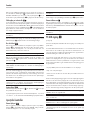
The RR-AX1400 Remote Control
Some functions can be done with either the front panel controls, or the
supplied RR-AX1400 remote control. When these operations are described,
the square call out numbers refer to the main unit, while the encircled letters
refer to the remote control.
Second Amplier Remote Code
The factory setting is remote code 1. If you nd that the remote is conicting
with other Rotel ampliers, you can change to remote code 2 with the
following steps.
1. From the remote control press Tuner
I
and 2
M
at the same time for 5
seconds, to set the remote control to send Audio Code 2.
2. Point the remote at the unit and press 2
M
button for 14 seconds. The
unit will show “Audio Code SET 1 -> 2”.
3. Repeat the above procedure and press “1” key instead of “2” to change
the unit back to Code 1.
NOTE: The remote control can be used to operate the basic functions
of Rotel tuners and CD players. Remote control keys labeled
GHMN
can be used to operate CD or Tuner functions in your system. For the
remote to operate properly, make sure both the remote and the CD or
Tuner are both in same remote code, either Code 1 or 2.
Remote Control Batteries
Two AAA size batteries (supplied) must be installed before the remote control
can be used. To install the batteries, remove the cover on the back of the
RR-AX1400. Install the batteries as shown in the illustration in the battery
well. Test the control for proper operation, then replace the cover. When the
batteries become weak the remote control won’t operate the A14 consistently.
Installing fresh batteries should eliminate the problem.
AC Power and Control
AC Power Input
s
Your unit is congured at the factory for the proper AC line voltage in the
country where you purchased it (either 120 volts AC or 230 volts AC with
a line frequency of either 50 Hz or 60 Hz). The AC line conguration is
noted on a decal on the back panel.
NOTE: Should you move your amplifier to another country, it is possible
to reconfigure it for use on a different line voltage. Do not attempt to
perform this conversion yourself. Opening the enclosure of the unit
exposes you to dangerous voltages. Consult a qualified service person
or the Rotel factory service department for information.
NOTE: Some products are intended for sale in more than one country
and as such are supplied with more than one AC cord. Please only use
the one appropriate for your country/region.
The unit does not draw high levels of current from the power outlet. However,
it should be plugged directly into a polarized wall outlet using the supplied
cable or other compatible cable as recommended by your authorized Rotel
dealer. Do not use an extension cord. A heavy duty multi-tap power outlet
strip may be used if it (and the wall outlet) can handle the current demanded
by the amplier and all the other components connected to it.
If you are going to be away from home for an extended period of time
such as a month-long vacation, it is a sensible precaution to unplug your
amplier (as well as other audio and video components) while you are away.

12
A14 Stereo Integrated Amplier
Power Switch
1
A
and Power Indicator
2
Press the front panel Power Switch button
1
, to turn the unit on. The Power
Indicator light
2
is illuminated when the unit is on. Press Power Switch
button again to turn the unit off.
When the power switch is in the ON position, the remote control ON and
OFF buttons may be used to activate the A14. In Standby mode the power
LED is red, but the display is turned OFF.
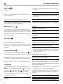
12V Trigger Connection
u
See Figure 5
Some audio components can be turned on automatically when they receive
a 12V turn on signal. The two 12V Trigger Outputs of the A14 unit provide
the required signal. Connect compatible components to the amplier with a
conventional 3.5mm mini plug cable. When the unit is in standby mode or
turned off, the trigger signal is interrupted, and the components controlled
by it are turned off.
NOTE: If you are using other units in the series with Rotel Link, please
use the Rotel Link connection to turn the units on or off. Do not connect
both the Rotel Link and 12V trigger cables. The 12V trigger’s power
on or off features will override the Rotel Link features.
Protection Indicator
2
The amplier has both thermal and over-current protection circuitry that
protects the amplier against damage in the event of extreme or faulty
operating conditions. The protection circuits are independent of the audio
signal and have no impact on sonic performance. Instead, the protection
circuits monitor the temperature of the output devices and shut down the
amplier if temperatures exceed safe limits.
Most likely, you will never see this protection circuitry in action. However,
should a faulty condition arise, the amplier will stop playing and will
display “AMP PROTECTION“ on the front panel. The power indicator 2
on the front panel will turn red.
If this happens, turn the amplier off. Let it cool down for several minutes,
and attempt to identify and correct the problem that caused the protection
circuitry to engage. When you turn the amplier back on, the protection
circuit will automatically reset and the power indicator 2 should turn blue.
In most cases, the protection circuitry activates because of a fault condition
such as shorted speaker wires, or inadequate ventilation leading to an
overheating condition. In very rare cases, highly reactive or extremely
low impedance speaker loads could cause the protection circuit to engage.
If the protection circuitry triggers repeatedly and you are unable to isolate
and correct the faulty condition, contact your authorized Rotel dealer for
assistance in troubleshooting.
Input Signal Connections
See Figure 3
NOTE: To prevent loud noises that neither you nor your speakers will
appreciate, make sure the system is turned off when you make any
signal connections.
Phono Input
-
and Ground Connection (GND)
0
Plug the cable from the turntable into the appropriate left and right phono
inputs. If the turntable has a “ground” wire, connect it to the screw terminal
to the left of the Phono inputs. It will help prevent hum and noise.
Line Level Inputs
=qw
The CD, Tuner, and Aux inputs of the amplier are “line level” inputs. These
are for connecting components such as CD players or other audio playback
devices with an analog audio output.
The Left and Right channels are labeled and should be connected to the
corresponding channels of the source component. The Left connectors
are white, the Right connectors are red. Use high quality RCA cables for
connecting input source components to the unit. Ask your authorized Rotel
dealer for advice about cables.
Digital Signal Inputs
]
See Figure 4
There are two sets of digital inputs labeled 1 and 2 for COAXIAL and
OPTICAL respectively. Connect the COAXIAL or OPTICAL outputs of your
source component into these sockets. The digital signals will be decoded
and played by the amplier. The unit is capable of decoding PCM signals
up to 24 bit, 192kHz.
Preamp Output
[
The amplier has a set of preamp outputs labeled PRE OUT. The currently
selected source input is available from this output. Typically the PRE OUT
output is used to provide a signal to another integrated amplier or power
amplier, which is used to drive remote speakers.
NOTE: Changes to the settings of the Volume, Balance or Tone controls
affect the signal from the Preamp Output.
Speaker Outputs
\a
See Figure 3
Speaker Selector Switch
5
The amplier has two sets of speaker outputs, labeled “SPEAKER A”
\
and
“SPEAKER B”
a
. The speaker outputs are controlled by the A-B speaker
selector buttons
5
on the front panel or J on the remote control.
Speaker Selection
If only one set of speakers will be used at any given time, the speakers may
have an impedance as low as 4 ohms. If there are times when both the A
and B speakers will be used, all the speakers should have an impedance
of 8 ohms or more. Speaker impedance ratings are less than precise. In
practice, very few loudspeakers will present any problems for the unit. See
your authorized Rotel dealer if you have any questions.
Speaker Wire Selection
Use insulated two-conductor stranded wire to connect the unit to the speakers.
The size and quality of the wire can have an audible effect on the performance
of the system. Standard speaker wire will work, but can result in lower
output or diminished bass response, particularly over longer distances. In
general, heavier wire will improve the sound. For best performance, you
may want to consider special high-quality speaker cables. Your authorized
Rotel dealer can help in the selection of cables for your system.

13
Polarity and Phasing
The polarity - the positive/negative orientation of the connections - for every
speaker and amplier connection must be consistent so all the speakers will
be in phase. If the polarity of one connection is reversed, bass output will
be very weak and stereo imaging degraded. All wire is marked so you can
identify the two conductors. There may be ribs or a stripe on the insulation
of one conductor. The wire may have clear insulation with different color
conductors (copper and silver). There may be polarity indications printed
on the insulation. Identify the positive and negative conductors and be
consistent with every speaker and amplier connection.
Speaker Connection
Turn off all the components in the system before connecting the speakers.
The amplier has color-coded binding post type speaker connectors on the
back panel. These connectors accept bare wire, connector lugs, or dual
banana type connectors. (Except in European Community countries where
their use is not permitted.)
Route the wire from the amplier to the speakers. Give yourself enough slack
so you can move the components to allow access to the speaker connectors.
If you are using dual banana plugs, connect them to the wires and then
plug into the backs of the binding posts. The thumbscrews of the binding
posts should be screwed in all the way (clockwise).
If you are using terminal lugs, connect them to the wires. If you are attaching
bare wires directly to the binding posts, separate the wire conductors and
strip the insulation from the end of each conductor. Be careful not to cut
into the wire strands. Unscrew (turn counterclockwise) the binding post
thumbscrews. Place the connector lug or wire around the binding post
shaft. Turn the thumbscrews clockwise to clamp the connector lug or wire
rmly in place.
NOTE: Be sure there are no loose wire strands that could touch adjacent
wires or connectors.
Headphone Output
4
The headphone output allows you to connect headphones for private listening.
This output accepts a standard 3.5mm (1/8”) mini stereo headphone
connector. Plugging in a set of headphones does not cut off the signal to the
speakers. Use the front panel
5
or remote control
J
A-B speaker selector
buttons to turn off the speakers.
NOTE: Because the sensitivity of speakers and headphones can
vary widely, always reduce the volume level before connecting or
disconnecting headphones.
Display
6
The front panel display shows the source selected, volume level and tone
settings. The display provides access to the setup and conguration menu
options of the amplier.
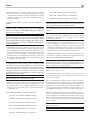
Front USB Input
3
The front USB input can be connected to an iPhone, iPad or iPod device
providing music playback to the amplier. To enable audio playback using
one of these devices simply plug the device into the front USB and select
USB as the desired source. The device will remain active allowing search
and play functions.
APTX Bluetooth Connection
e
The Bluetooth Antenna e on the A14’s back panel is for wireless streaming
via Bluetooth, from your device (i.e. mobile phones, tablets or computers).
From your device, look for “Rotel Bluetooth” and connect to it. Connection
is normally automatic, but if prompted for a password, please enter “0000”
on your device. The A14’s supports both traditional Bluetooth and APTX
Bluetooth audio streaming.
Rear USB Power Port
p
The rear USB port provides 5V/0.5A for charging or powering USB devices
including streaming music players. This port does not allow playback of audio.
The port can be congured to remain powered even when the A14 is in
standby mode through the front panel setup menu (See USB POWER option
on page 15).
This conguration option allows the attached streaming source to remain
powered for use with the Signal Sense function for automatic power on/
off control of the amplier.
NOTE: When configured to provide continuous power to the rear
panel USB port the A14 will consume additional power even when in
standby mode.
Audio Controls
Volume Control
7
E
Turn the control clockwise to increase the volume, or counter clockwise to
decrease the volume. From the remote control press the volume + or - button
to turn the volume up or down. Press the MUTE
F
button to completely
mute the volume.
Balance Control
9
B
The Balance Control adjusts the left-to-right balance of the sound output. The
factory default is the center position or “0”. To change the balance from
the front panel, press the MENU
9
button to toggle the front display to
BALANCE setting mode. Then press the - or + buttons on the front panel to
change the value to LEFT or RIGHT. The value can change from L15 to R15.
NOTE: This setting is saved permanently including after powering off
the A14.
To make temporary changes not saved after power off, from the remote,
press the BAL
B
button to access the BALANCE SETTING menu, then press
the up/down/left/right
C
arrow buttons to adjust.
Tone Control Bypass
9
B
Bass and Treble Control (Tone Control) circuits are bypassed at factory
default to ensure the purest possible sound. The front display will show
TONE BYPASS. To turn on the tone control from the front panel, press the
MENU
9
button to toggle to the Bypass control then press the - or + buttons
to turn bypass on or off.

14
A14 Stereo Integrated Amplier
NOTE: This setting is saved permanently including after powering off
the A14.
To temporarily changes the Tone Control Bypass, press the BYPASS
B
button
on the remote control to toggle the Bypass mode enabled and disabled.
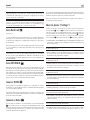
Bass and Treble Controls
9
B
Set the Bass or Treble controls from the front panel by pressing the MENU
9
button to the Bass and Treble Setting menu in sequence. Press the - or +
buttons to adjust the value. The Bass and Treble values range from -10 to +10.
NOTE: These settings are saved permanently including after powering
off the A14.
To temporarily change the Bass and Treble settings from the remote control,
press the BASS or TREB
B
button, then press the up/down/left/right
C
arrow buttons on the remote to adjust the value.
NOTE: Bass and Treble changes are only available when Tone Bypass
is disabled (see Tone Control Bypass section).
A properly setup high-performance audio system produces the most natural
sound with little or no adjustment of the tone controls. Use these controls
sparingly. Be particularly careful when turning the controls up. This increases
the power output in the bass or treble range, increasing the load on the
amplier and speakers.
NOTE: Setting the Bass and Treble controls do not automatically turn
on the tone control. To turn on tone control, refer to previous section
Tone Control Bypass.
Source Input Selector
8
I
Press the corresponding input button on the front panel
8
or remote control
I
to select the desired listening source.
Push the front panel source buttons to toggle between Optical 1 - 2, Coaxial
1- 2 and Aux 1 - 2 or use the dedicated source button on the remote control.
Dimmer Control
Display Dimmer
9
D
To change the brightness of the front display, press the MENU
9
button
to toggle to the DIMMER Settings. Then press the - or + buttons on the front
panel to change the display brightness.
NOTE: This setting is saved permanently including after powering off
the A14.
To temporarily change the display brightness, press the DIM
D
button on
the remote.
LED Dimmer
9
To change the brightness of the Power LED and the two Speaker Selector
LEDs on the front panel, press the MENU
9
button to toggle to the LED
DIMMER Settings. Then press the - or + buttons on the front panel to change
the LEDs brightness.
NOTE: This setting is saved permanently including after powering off
the A14.
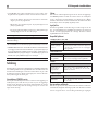
PC-USB Input r
See Figure 4
Connect this input using the supplied USB cable to the PC-USB socket of
your computer.
The A14 supports both USB Audio Class 1.0 and USB Audio Class 2.0
modes. Windows computers do not require installation of a driver for USB
Audio Class 1.0 and support playback of audio up to 96kHz sampling
rates. The Factory Default setting is USB Audio Class 1.0.
To take advantage of USB Audio Class 2.0 audio playback supporting up to
384kHz sampling rates you will need to install the Windows driver supplied
on the CD included with the A14. You will also need to switch the A14 to
USB Audio Class 2.0 playback mode with the following:
• Press MENU on the front panel until “PC-USB CLASS” appears on the display.
• Select “2.0” using the “+” button.
• Power cycle the A14 and reboot your PC after changing the USB Audio
mode to ensure both units are properly congured.
Many audio playback applications do not support 384kHz sampling rate.
Please conrm your audio player supports 384kHz audio and you have
384kHz audio les to properly playback this sample rate. Also, you may
need to congure the audio driver in your PC to output 384kHz or your
computer may “down sample” to a lower audio sample rate. For more
information please refer to your audio player or operating system information.
NOTE: USB Audio Class 2.0 requires installation of the Windows PC
driver on the CD ROM included with the A14.
NOTE: MAC computers do not require a driver to support PC-USB
Audio Class 1.0 or 2.0.
NOTE: Upon successful installation of the driver, you may need to select
the ROTEL audio driver from the audio/speaker setup of your computer.
NOTE: The A14 supports both DSD and DOP audio playback in 1X
and 2X formats. Consult your audio player to confirm proper operation
for playback of these audio formats.
Rotel Link
t
See Figure 5
The ROTEL LINK OUT connection can be made with the stereo 3.5 mm cable
(supplied) to a Rotel product with ROTEL LINK IN connection including a
CD player.
These allow the attached Rotel products to communicate with each other and
be controlled via the Rotel App (available for download on the iTunes
®
store).
NOTE: Only the Rotel Link cables supplied with this product should be
used. These 3.5 mm cables have WHITE connector ends and should
not be confused with the 12 Volt Trigger cables that have BLACK
connector ends.

15
EXT REM IN Jack
y
This 3.5mm mini-jack receives command codes from industry-standard infrared
receivers via hard-wired connections. This feature could prove useful when
the unit is installed in a cabinet and the front-panel sensor is blocked. Consult
your authorized Rotel dealer for information on these external repeaters and
the proper wiring of a jack to t the mini-jack receptacle.
RS232 Connector
i
The A14 can be controlled via RS232 for integration with automation systems.
The RS232 input accepts a standard straight DB-9 Male-to-Female cable.
For additional information on the connections, software, and operating
codes for RS232 control of the A14, contact your authorized Rotel dealer.
Network Connection
o
The A14 can be attached to a network using the rear panel NETWORK
socket o. The NETWORK congurations allow both STATIC and DHCP
IP addressing. See the Network section of this manual under Setting Menu
for IP address conguration information.
The NETWORK connection allows software updates to be downloaded from
the Internet. The NETWORK connection also allows IP control for integration
with automation systems.
For additional information on the IP control please contact your authorized
Rotel dealer.
Settings Menu
You can access the SETUP menu from the front panel by pressing the MENU
9
button or the
K
button on the remote. You can change the value of
the selected option by pressing the - or + buttons on the front panel or the
up/down/left/right
C
arrow buttons on the remote. Step through the
sub-menus by pressing the MENU
9
button on the front panel or the
K
button on the remote.
• TONE BYPASS: TONE BYPASS on/off (For more information refer to Tone
Control Bypass section).
NOTE: This setting is stored permanently even after the A14 is powered
off.
• BASS: BASS level can be changed to desired settings. (For more information
refer to Bass and Treble Control section.)
NOTE: This setting is stored permanently even after the A14 is powered
off.
• TREBLE: TREBLE level can be changed to desired settings. (For more
information refer to Bass and Treble Control section.)
NOTE: This setting is stored permanently even after the A14 is powered
off.
• BALANCE: Change left/right balance. (For more information refer to
Balance Control section.)
NOTE: This settings is stored permanently even after the A14 is
powered off.
• DIMMER: Dims the front display.
NOTE: This setting is stored permanently even after the A14 is powered
off.
• LED DIMMER: Dims the Power LED and the LEDs above the Speaker Selector
buttons on the front panel.
NOTE: This setting is stored permanently even after the A14 is powered
off.
• POWER ON MAX VOL: This sets the maximum volume level when the unit
is turned on. “45” is the factory default.
NOTE: Power On Max Volume settings do not apply to sources
configured with Fixed Gain.
• POWER MODE: Enables the A14 to be controlled via the network port
when attached to an automation system. The power consumption is higher
in Quick Power mode. If network control is not required select the Normal
Power mode. “Normal” is the factory default.
Valid settings include: Quick, Normal.
NOTE: When the POWER MODE is configured to Quick, the A14 will
consume additional power in standby mode.
NOTE:: Some regions limit the amount of Standby Power Consumption
allowed and the POWER MODE will not be available. To control the
Rotel product in this case use the RS232 connection. For questions
on the availablity of the Power Mode please contact your authorized
Rotel dealer.
• USB POWER: This option allows the rear panel USB connector to provide
power, even when the A14 is in standby mode.
To enable the continuous power mode select the ALWAYS option. To provide
power only when the A14 is powered on, select the NORMAL option. The
default for USB POWER is set to NORMAL.
NOTE: The front panel power button must be in the ON position to
supply power to the rear panel USB connector.
NOTE: When the USB POWER is configured to ALWAYS the A14 will
consume additional power in standby mode to supply USB power.
• OFF TIMER: The A14 can be congured to automatically power off if
unused for a specied period. If no changes are made to the unit within
the specied “Off Timer” period, the unit will automatically go to STANDBY
mode. The auto power off timer will be restarted if changes are made to
the volume, source or playback. The default for Off Timer is set to DISABLE.
Valid settings include: DISABLE, 1 HOUR, 2 HOURS, 5 HOURS, 12 HOURS.

16
A14 Stereo Integrated Amplier
NOTE:: Some regions require the Off Timer default setting to be
20 minutes. This can be changed in the SETUP MENU to any of the
available options. For questions about the Off Timer settings please
contact your authorized Rotel dealer.
NOTE:: Some products cannot detect ANALOG signal inputs and
the unit may power off if there is no digital audio source detected or
user action with the remote control or front panel. Analog input signal
detection is not available in all models which may cause the unit to
inadvertently power off. In this case the Off Timer should be set to
DISABLED.
• SIGNAL SENSE: Check if a digital audio signal is present on the congured
Signal Sense input. When this input is selected as the active listening
source, the A14 monitors the digital data stream to determine if there is
audio. If there is no audio detected for 10 minutes, the A14 will enter
Signal Sense Standby Mode. When in Signal Sense Standby Mode and
the A14 detects audio on Signal Sense input, the unit will automatically
power on. To disable this function, select the OFF option which is the
factory default setting.
NOTE: Recent software versions allow the configured Signal Sense
input to be active in Standby Mode regardless of source input active
when the unit was powered off to standby. Previous version of software
required the Signal Sense configured input to be the active source when
the unit was powered off for Signal Sense to become active and monitor
the configured input for audio. For more information and details on
supported software versions and software update steps please contact
your authorized Rotel dealer.
NOTE: When the SIGNAL SENSE function is activated the A14 will
consume additional power in signal sense standby mode.
• FIXED GAIN: Congures a Fixed Volume level for a specied input. To
enable this feature, select the desired xed volume level for AUX1, AUX2,
USB, PC-USB, Optical 1, Optical 2, Coax 1, Coax 2, or Bluetooth. When
enabled and the input with a Fixed Volume is selected, the Volume level
will immediately be set to the specied level.
Valid settings include: VARIABLE, FIXED MIN, FIXED 01-95, FIXED MAX.
• AUX1 VOL: VARIABLE (disabled) is factory default.
• AUX2 VOL: VARIABLE (disabled) is factory default.
• USB VOL: VARIABLE (disabled) is factory default.
• PC-USB VOL: VARIABLE (disabled) is factory default.
• OPT1 VOL: VARIABLE (disabled) is factory default.
• OPT2 VOL: VARIABLE (disabled) is factory default.
• COAX1 VOL: VARIABLE (disabled) is factory default.
• COAX2 VOL: VARIABLE (disabled) is factory default.
• BTOOTH VOL: VARIABLE (disabled) is factory default.
NOTE: The Volume knob on the front panel and Volume +/- buttons
on the IR remote are disabled when the volume is Fixed. To disable this
feature set the Fixed Volume level to “Variable”.
• PC-USB CLASS: Change supported PC-USB Audio Class of the attached
device.
NOTE: Some computers attached to the PC-USB do not support USB
Audio Class 2.0 and do not support 32/384 audio playback. If needed
the PC-USB can be configured for USB Audio Class 1.0. Please refer
to your computer operating system for details.
• VIEW NETWORK: Shows the network connection status and to view
the network settings. To view the network settings, press the + button on
the front panel or the ENT button on the remote control. If the network is
properly congured and attached, “Connected” will be displayed. To view
additional network conguration details, including IP Address information,
press the MENU button to toggle through the settings.
• CONFIGURE NETWORK: Allows conguration of the network IP settings.
To enter the Network Conguration menu option press the + button on the
front panel or the ENT button on the remote control.
NOTE: Configuration of the network requires the use of the remote
control to enter the IP address details. This setup cannot be completed
using the front panel controls. Please ensure you have access to the
remote control before proceeding with Network Configuration.
To begin conguration of the network, press the ENT button on the remote
control and follow as below:
The A14 supports both DHCP and STATIC IP addressing. Select the desired
IP address method with the left/right arrow buttons on the remote control
and press ENT to conrm.
If DHCP is selected, the A14 will refresh the IP address after pressing the ENT
button on the remote control to conrm. The refresh process could take up
to 10 seconds. The display will indicate if the DHCP refresh was successful.
If the refresh process failed, check the network connections and try again
by pressing the ENT button on the remote control. To exit the DHCP refresh
process, press the MENU button.
If STATIC IP address mode is selected, you must congure all settings for the
network, including IP Address, Subnet Mask, Gateway and DNS Server.
Use the up/down arrow buttons on the remote control to adjust the values
and press the left/right buttons on the remote control to move to the next
section. When the proper IP information is congured press ENT to conrm.
NOTE: For more information regarding network connection please
contact your authorized Rotel dealer.
NOTE: A network connection is not required for the A14 to operate.
• S/W VERSION: This shows the current software version loaded into the
A14. The software can be updated if the A14 is properly connected to
the Internet.
• Press the “+” button on the front panel to check if a new software
version is available.

17
• If a new software version is available, press the “+” button on the
front panel, to begin the software update process.
• The new software will be downloaded from the Internet. The A14
will power cycle when the software update is complete.
NOTE: Do NOT power off the A14 during the software update process.
NOTE: It is recommended to Reset Factory Defaults after the software
update is complete.
• PC-USB VERSION: This shows current loaded software version for PC-USB
processor.
• FACTORY DEFAULT: This sets the unit back to the original state as when it
left the factory. Press the “+” button on the front panel or the ENT button
on the remote control to enter factory reset setting. And then press the “+”
button or ENT again to begin reset, or press the MENU button to cancel.
NOTE: All previously configured options will be erased and reset to
the factory default settings.
Troubleshooting
Most difculties in audio systems are the result of incorrect connections, or
improper control settings. If you encounter problems, isolate the area of the
difculty, check the control settings, determine the cause of the fault and
make the necessary changes. If you are unable to get sound from the unit,
refer to the suggestions for the following conditions:
Power Indicator Is Not Illuminated
The Power Indicator and the basic items in the Display window should be
illuminated whenever the unit is plugged into the wall power outlet and the
Power button is pushed in. If it does not illuminate, test the power outlet with
another electrical device, such as a lamp. Be sure the power outlet being
used is not controlled by a switch that has been turned off.
Fuse Replacement
If another electrical device works when plugged into the power outlet, but
the Power Indicator still will not illuminate when the unit is plugged into
the wall outlet, it indicates that the internal power fuse may have blown.
If you believe this has happened, contact your authorized Rotel dealer to
get the fuse replaced.
No Sound
Check the signal source to see if it is functioning properly. Make sure the
cables from the signal source to the amplier inputs are connected properly.
Be sure the Input Source is set to the proper input. Check the wiring between
the amplier and the speakers.
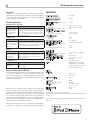
Playable Audio Formats
USB Apple (iPhone, iPod, iPad)
Format Notes
Any supported file
loaded to Apple device.
Any supported le loaded to Apple device. Phone may
resample depending on stored format. May exclude
Apps designed to play formats not originally supported
by the sending device.
APTX Bluetooth
Format Notes
Any format supported
by the sending device.
May exclude Apps designed to play formats not originally
supported by the sending device.
PC-USB
Format Notes
Format determined
by the Media Player/
Server software that
you use.
Any supported format by the PC software
PCM Audio:
44.1k, 48k, 88.2k, 96k, 176.4k, 192k, 384k
(16 bit, 24 bit and 32 bit)
DSD64 and DSD128
Coax/Optical
Format Notes
SPDIF LPCM
44.1k, 48k, 88.2k, 96k, 176.4k, 192k
16 bit, 24 bit
Cannot Connect via Bluetooth
If you cannot pair your Bluetooth enabled device to the A14, delete the
memory of the previous connection on your device. On your device this is
often listed as “Forget this Device”. Then try to make the connection again.

18
A14 Stereo Integrated Amplier
“Made for iPod,” and “Made for iPhone,” means that an electronic accessory
has been designed to connect specically to iPod or iPhone, respectively, and
has been certied by the developer to meet Apple performance standards.
Apple is not responsible for the operation of this device or its compliance with
safety and regulatory standards. Please note that the use of this accessory
with iPod, or iPhone may affect wireless performance.
iPhone, iPod, iPod classic, iPod nano, and iPod touch are trademarks of
Apple Inc., registered in the U.S. and other countries.
Specications
Continuous Power Output 80 watts/ch
(20 - 20k Hz, < 0.03%, 8 ohms)
Total Harmonic Distortion (20 Hz - 20k Hz, 8 ohms) < 0.03%
Intermodulation Distortion (60 Hz : 7k Hz, 4:1) < 0.03%
Frequency Response
Phono Input 20 Hz - 20k Hz, ± 0.5 dB
Line Level Inputs 10 Hz - 100k Hz, ± 0.5 dB
Damping Factor (20 - 20,000 Hz, 8 ohms) 220
Input Sensitivity / Impedance
Phono Input 3.4 mV / 47k Ohms
Line Level Inputs 230 mV / 24k Ohms
Input Overload
Phone Input 50 mV
Line Level Inputs 4 V
Preamp Output / Impedance 1.2 V / 470 Ohms
Tone Controls - Bass / Treble ± 10 dB at 100 Hz / 10k Hz
Signal to Noise Ratio (A weighting)
Phono Input 90 dB
Line Level Inputs 100 dB
Digital Section
Frequency Response 10Hz - 80k Hz (± 3.0dB,MAX)
Signal to Noise Ratio (A weighting) 103 dB
Input Sensitivity/Impedance 0 dBfs/75 ohms
Preamplifier Output Level 1.3 V (at - 20dB)
Digital Inputs SPDIF LPCM
(up to 192k Hz 24 bit)
PC-USB USB Audio Class 1.0
(up to 96kHz 24bit)
USB Audio Class 2.0
(up to 384kHz 32bit)*
*Driver installation required
DSD and DoP support
General
Power Requirements
USA 120V, 60 Hz
EC 230V, 50 Hz
Standby Power Consumption < 0.5W
Power Consumption 280 Watts
BTU (4 ohms, 1/8th power) 632 BTU/h
Rear USB Output 5 V / 0.5 A
Dimensions (W, H, D) 430 x 93 x 345 mm
17” x 3
5
/8” x 13
1
/2”
Panel Height 80 mm / 3
1
/8”.
Weight (net) 8.2 kg, 18 lbs.
All specications are accurate at the time of printing.
Rotel reserves the right to make improvements without notice.
Rotel and the Rotel HiFi logo are registered trademarks of The Rotel Co., Ltd.
Tokyo, Japan.

PB 19
A14 Amplicateur Stéréo Intégré
Remarque
La prise RS232 ne doit être utilisée que par une personne qualifiée.
ATTENTION : Il n’y a à l’intérieur aucune pièce susceptible d’être modifiée
par l’utilisateur. Adressez-vous impérativement à une personne qualifiée.
ATTENTION : Pour réduire tout risque d’électrisation ou d’incendie, ne
pas exposer l’appareil à une source humide, ou à tout type de risque
d’éclaboussure ou de renversement de liquide. Ne pas poser dessus
d’objet contenant un liquide, comme un verre, un vase, etc. Prenez
garde à ce qu’aucun objet ou liquide ne tombe à l’intérieur de l’A14
par ses orifices de ventilation. Si l’appareil est exposé à l’humidité ou
si un objet tombe à l’intérieur, débranchez-le immédiatement de son
alimentation secteur, et adressez-vous immédiatement et uniquement
à une personne qualifiée et agréée.
Tous les conseils de sécurité et d’installation doivent être lus.
Conservez soigneusement ce livret.
Tous les conseils de sécurité doivent être soigneusement respectés.
Respectez les procédures d’installation et de fonctionnement indiquées
dans ce manuel.
Ne pas utiliser cet appareil près d’un point d’eau.
L’appareil doit être nettoyé uniquement avec un chiffon sec ou un
aspirateur.
Il ne doit pas être posé sur un fauteuil, un canapé, une couverture ou
toute autre surface susceptible de boucher ses ouïes d’aération ; ou
placé dans un meuble empêchant la bonne circulation d’air autour des
orifices d’aération.
Cet appareil doit être placé loin de toute source de chaleur, tels que
radiateurs, chaudières, bouches de chaleur ou d’autres appareils
produisant de la chaleur.
Notamment, ne pas tenter de supprimer la prise de terre (troisième broche
de la prise) si celle-ci est présente. Si la prise n’est pas conforme à celles
utilisées dans votre installation électrique, consultez un électricien agréé.
Prendre garde à ce que ce cordon d’alimentation ne soit pas pincé,
écrasé ou détérioré sur tout son trajet, et à ce qu’il ne soit pas mis en
contact avec une source de chaleur. Vérifiez soigneusement la bonne
qualité des contacts, à l’arrière de l’appareil comme dans la prise murale.
N’utilisez que des accessoires préconisés par le constructeur.
N’utilisez que des meubles, supports, systèmes de transport
suffisamment solide pour supporter l’appareil. Procédez
toujours avec la plus extrême précaution lorsque vous
déplacez l’appareil, afin d’éviter tout risque de blessure
ou des dommages à l’appareil.
Débranchez le câble d’alimentation en cas d’orage, ou si l’appareil ne
doit pas être utilisé pendant une longue période.
L’appareil doit être immédiatement éteint, débranché puis retourné au
service après-vente agréé dans les cas suivants :
le câble d’alimentation
secteur ou sa prise est endommagé; un objet est tombé, ou du liquide
a coulé à l’intérieur de l’appareil; l’appareil a été exposé à la pluie;
l’appareil ne fonctionne manifestement pas normalement; l’appareil
est tombé, ou le coffret est endommagé.
L’appareil doit être utilisé dans un climat non tropical.
Tous les appareils Rotel sont conçus en totale
conformité avec les directives internationales
concernant les restrictions d’utilisation de substances
dangereuses (RoHS) pour l’environnement, dans
les équipements électriques et électroniques, ainsi
que pour le recyclage des matériaux utilisés (WEEE,
pour Waste Electrical and Electronic Equipment).
Le symbole du conteneur à ordures barré par une
croix indique la compatibilité avec ces directives, et
le fait que les appareils peuvent être correctement
recyclés ou traités dans le respect total de ces normes.
Ce symbole signifie que cet appareil bénéficie d’une
double isolation électrique. Le branchement d’une
mise à la masse ou à la terre n’est pas nécessaire.
Remarques importantes concernant la sécurité
Vous devez réserver un espace libre d’une dizaine de
centimètres minimum autour de l’appareil.
ATTENTION : La prise d’alimentation située à l’arrière constitue le
principal moyen pour déconnecter l’appareil du secteur. Cet équipement
doit être positionné dans un espace ouvert qui permet de garder l‘accès
au câble d’alimentation.
Cet appareil doit être branché sur une prise d’alimentation secteur, d’une
tension et d’un type conformes à ceux qui sont indiqués sur la face arrière
de l’appareil (USA : 120 V/60 Hz, CE : 230 V/50 Hz).
Brancher l’appareil uniquement grâce au cordon secteur fourni, ou à
un modèle équivalent. Ne pas tenter de modifier ou changer la prise.
Ne pas utiliser de cordon rallonge.
La prise d’alimentation secteur constitue le moyen radical de déconnexion
de l’appareil. Elle doit donc rester en permanence accessible, car sa
déconnexion constitue la seule assurance que l’appareil n’est plus
alimenté par le secteur.
Utilisez uniquement des câbles de Classe 2 pour réalise les connexions aux
enceintes acoustiques et offrant une isolation suffisante pour minimiser
les risques de chocs électriques.
Les piles de la télécommande infra-rouge ne doivent en aucun cas
exposées à une chaleur excessive notamment au feu ou au soleil
direct. Les batteries doivent être recyclées ou éliminées selon les
directives nationales et locales.
POWER
PHONES
A12
PHONO TUNER CD USB OPT COAX AUX PC-USB BT
5V / 2.1A
MENU
SPEAKERS
A B
POWER
PHONES
A14
PHONO TUNER CD USB OPT COAX AUX PC-USB BT
5V
/
2.1A
MENU
SPEAKERS
A B
L’éclair dans un triangle équilatéral indique
la présence interne de tensions électriques
élevées susceptibles de présenter des
risques graves d’électrocution.
Le point d’exclamation dans un triangle
équilatéral indique à l’utilisateur la
présence de conseils et d’informations
importantes dans le manuel d’utilisation
accompagnant l’appareil. Leur lecture est
impérative.

20
A14 Amplicateur Stéréo Intégré
A propos de Rotel
Notre histoire commence il y a environ 50 ans. Depuis, au l des années,
nous avons reçu des centaines de prix et de récompenses, et satisfait des
centaines de milliers de personnes – comme vous !
Rotel a été fondée par une famille passionnée de musique, qui a décidé de
fabriquer des maillons Haute Fidélité sans compromis aucun.
Depuis sa création, cette passion est restée intacte, et cette famille s’est
xée comme objectif de proposer à tous les audiophiles et mélomanes
les meilleurs appareils possibles, quel que soit leur budget. Une volonté
partagée par tous les employés de Rotel.
Les ingénieurs Rotel travaillent comme une équipe très soudée, écoutant,
peaunant chaque nouveau modèle jusqu’à ce qu’il atteigne exactement
leurs standards – très élevés – de musicalité. Ils sont libres de choisir des
composants en provenance du monde entier, an de concevoir le meilleur
produit possible. C’est ainsi que vous trouverez dans nos appareils des
condensateurs d’origine britannique ou allemande, des transistors japonais
ou américains, tandis que les transformateurs toriques sont toujours fabriqués
dans nos propres usines Rotel.
Nous sommes tous concernés par la qualité de l’environnement. Et, comme de
plus en plus de produits électroniques sont fabriqués puis éliminés quelques
années plus tard, il est désormais essentiel qu’un constructeur fabrique tous
ses produits en veillant à ce qu’ils aient un impact minimum sur la planète.
Chez Rotel, nous sommes très ers d’apporter notre pierre à ce nouvel édice.
Nous avons réduit la teneur en plomb de nos électroniques, en utilisant
notamment des composants et une soudure spéciale ROHS. Nos ingénieurs
travaillent en permanence pour améliorer le rendement des alimentations de
puissance sans compromettre leur qualité. C’est ainsi qu’en mode Standby,
les appareils Rotel consomment moins pour se conformer aux exigences
de la « Standby Power Consumption » qui limite la consommation en veille
des appareils électroniques.
L’usine Rotel participe également de façon active à la protection de
l’environnement au travers d’un processus de fabrication général amélioré
et toujours plus écologique et plus propre.
Tous les membres de l’équipe Rotel vous remercient pour l’achat de cet
appareil. Nous sommes persuadés qu’il vous offrira de nombreuses années
d’intense plaisir musical.
Mise en route
Merci d’avoir acheté cet Amplicateur Stéréo Intégré Rotel A14. Associé
à un ensemble audio de qualité, il vous offrira de nombreuses années de
plaisir musical.
Cet amplicateur est un élément hautes performances doté de fonctionnalités
avancées. Tous les aspects de sa conception ont été optimisés pour garantir
une dynamique sans faille et restituer les nuances les plus subtiles de votre
musique. L’appareil dispose d’une alimentation hautement régulée intégrant
un transformateur de puissance toroïdal spéciquement conçu par Rotel. Cette
alimentation basse impédance dispose de réserves d’énergie importantes
et permet à l’amplicateur de prendre facilement en charge tous les types
de signaux audio, même les plus exigeants. Ce type de composant est plus
cher à fabriquer, mais il est d’une qualité supérieure sur le plan musical.
Sommaire
Figure 1 : Commandes et Branchements 3
Figure 2 : Télécommande RR-AX1400 4
Figure 3 : Entrées préampli et sorties pour enceintes acoustiques 5
Figure 4 : Branchements Entrées numériques 6
Figure 5 : Branchements Rotel Link et trigger 12 V 7
Figure 6 : Entrée USB en face avant 8
Remarques importantes 9
Remarques importantes concernant la sécurité ............................19
A propos de Rotel .................................................20
Mise en route ....................................................20
Quelques précautions préalables 21
Installation 21
Câbles 21
Télécommande infrarouge RR-AX1400 ...................................21
Code secondaire de télécommande 21
Piles de la télécommande 21
Alimentation secteur et commandes .....................................22
Prise secteur
s
22
Interrupteur de mise sous tension/veille Standby
1A
et indicateur Power
2
22
Branchement trigger 12 V
u
22
Indicateur de protection
2
..........................................22
Connexions d’entrée du signal ........................................22
Entrée Phono
-
et connexion à la masse [GND]
0
22
Entrées Lignes
=qw
22
Entrées Numériques
]
23
Sortie Préampli
[
................................................23
Sorties pour enceintes acoustiques
\a
................................23
Commutateur de sélection des enceintes acoustiques
5
23
Choix des enceintes acoustiques 23
Choix des câbles d’enceintes acoustiques 23
Polarité et Phase 23
Branchement des enceintes 23
Sortie Casque
4
.................................................23
Afcheur
6
.....................................................23
Entrée USB en face avant
3
.........................................24
Connexion Bluetooth APTX
e
........................................24
Port USB en face arrière
p
..........................................24
Commandes Audio .................................................24
Contrôle de volume
7E
24
Réglage de balance
9B
24
Activation/désactivation du contrôle de tonalité
9B
24
Ajustements Graves/Aigus
9B
24
Le sélecteur d’entrée de source
8I
24
Contrôle de luminosité de l’afchage ...................................25
Luminosité de l’écran
9D
25
Luminosité des LED
9
25
Entrée pour PC-USB
r
.............................................25
ROTEL LINK
t
...................................................25
Prise jack pour télécommande externe (EXT REM IN)
y
.....................25
Prise RS232
i
..................................................25
Connexion réseau
o
...............................................26
Menu de conguration ..............................................26
Problèmes de fonctionnement .........................................28
L’indicateur de mise sous tension n’est pas allumé 28
Remplacement du fusible 28
Pas de son 28
Formats de lecture compatibles 28
Pas de connexion via Bluetooth 28
Spécications ....................................................29
Sidan laddas ...
Sidan laddas ...
Sidan laddas ...
Sidan laddas ...
Sidan laddas ...
Sidan laddas ...
Sidan laddas ...
Sidan laddas ...
Sidan laddas ...
Sidan laddas ...
Sidan laddas ...
Sidan laddas ...
Sidan laddas ...
Sidan laddas ...
Sidan laddas ...
Sidan laddas ...
Sidan laddas ...
Sidan laddas ...
Sidan laddas ...
Sidan laddas ...
Sidan laddas ...
Sidan laddas ...
Sidan laddas ...
Sidan laddas ...
Sidan laddas ...
Sidan laddas ...
Sidan laddas ...
Sidan laddas ...
Sidan laddas ...
Sidan laddas ...
Sidan laddas ...
Sidan laddas ...
Sidan laddas ...
Sidan laddas ...
Sidan laddas ...
Sidan laddas ...
Sidan laddas ...
Sidan laddas ...
Sidan laddas ...
Sidan laddas ...
Sidan laddas ...
Sidan laddas ...
Sidan laddas ...
Sidan laddas ...
Sidan laddas ...
Sidan laddas ...
Sidan laddas ...
Sidan laddas ...
Sidan laddas ...
Sidan laddas ...
Sidan laddas ...
Sidan laddas ...
Sidan laddas ...
Sidan laddas ...
Sidan laddas ...
Sidan laddas ...
Sidan laddas ...
Sidan laddas ...
Sidan laddas ...
Sidan laddas ...
Sidan laddas ...
Sidan laddas ...
Sidan laddas ...
Sidan laddas ...
Sidan laddas ...
Sidan laddas ...
Sidan laddas ...
Sidan laddas ...
Sidan laddas ...
Sidan laddas ...
Sidan laddas ...
Sidan laddas ...
-
 1
1
-
 2
2
-
 3
3
-
 4
4
-
 5
5
-
 6
6
-
 7
7
-
 8
8
-
 9
9
-
 10
10
-
 11
11
-
 12
12
-
 13
13
-
 14
14
-
 15
15
-
 16
16
-
 17
17
-
 18
18
-
 19
19
-
 20
20
-
 21
21
-
 22
22
-
 23
23
-
 24
24
-
 25
25
-
 26
26
-
 27
27
-
 28
28
-
 29
29
-
 30
30
-
 31
31
-
 32
32
-
 33
33
-
 34
34
-
 35
35
-
 36
36
-
 37
37
-
 38
38
-
 39
39
-
 40
40
-
 41
41
-
 42
42
-
 43
43
-
 44
44
-
 45
45
-
 46
46
-
 47
47
-
 48
48
-
 49
49
-
 50
50
-
 51
51
-
 52
52
-
 53
53
-
 54
54
-
 55
55
-
 56
56
-
 57
57
-
 58
58
-
 59
59
-
 60
60
-
 61
61
-
 62
62
-
 63
63
-
 64
64
-
 65
65
-
 66
66
-
 67
67
-
 68
68
-
 69
69
-
 70
70
-
 71
71
-
 72
72
-
 73
73
-
 74
74
-
 75
75
-
 76
76
-
 77
77
-
 78
78
-
 79
79
-
 80
80
-
 81
81
-
 82
82
-
 83
83
-
 84
84
-
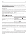 85
85
-
 86
86
-
 87
87
-
 88
88
-
 89
89
-
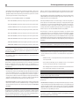 90
90
-
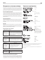 91
91
-
 92
92


Rotel A14 Bruksanvisning
- Kategori
- Kompletterande musikutrustning
- Typ
- Bruksanvisning
på andra språk
- italiano: Rotel A14 Manuale del proprietario
- español: Rotel A14 El manual del propietario
- Deutsch: Rotel A14 Bedienungsanleitung
- français: Rotel A14 Le manuel du propriétaire
- Nederlands: Rotel A14 de handleiding