
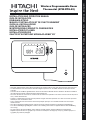
Wireless Programmable Room
Thermostat (ATW-RTU-02)
- Read and understand this manual before performing any operation with the unit. Keep this manual for future reference.
- Lea detenidamente este manual antes de realizar ninguna operación con la unidad. Guarde el manual para futuras
consultas.
- Lesen Sie dieses Handbuch gründlich durch, bevor Sie das Gerät in Betrieb nehmen. Bewahren Sie dieses Handbuch
für inder Zukunft eventuell auftretende Fragen oder Probleme auf.
- Lisez avec attention le contenu de ce manuel avant de réaliser toute opération avec l’unité. Conservez-le an de pouvoir
vous y référer ultérieurement.
- Leggere e comprendere il presente manuale prima di eseguire eventuali operazioni con l’unità. Conservare il presente
manuale per una consultazione futura.
- Leia e compreenda este manual antes de executar qualquer operação com a unidade. Guarde este manual para
referência futura.
- Læs denne vejledning grundigt igennem, inden du anvender enheden. Gem denne vejledning til fremtidig brug.
- Lees deze handleiding zorgvuldig door voordat u een handeling uitvoert met het apparaat. Bewaar deze handleiding
voor naslag.
- Läs noga igenom den här handboken innan du börjar använda enheten. Spara handboken för framtida bruk.
- Διαβάστε προσεκτικά αυτό το εγχειρίδιο πριν εκτελέσετε οποιαδήποτε λειτουργία με αυτήν την μονάδα. Κρατήστε το
εγχειρίδιο για μελλοντική αναφορά.
ΕΛΛΗΝΙΚΆ SVENSKA NEDERLANDS DANSK PORTUGUÊS ITALIANO FRANÇAIS DEUTSCH ESPAÑOL ENGLISH
INSTALLATION AND OPERATION MANUAL
GUÍA DE INSTALACIÓN
EINBAUANLEITUNG
MANUEL D’INSTALLATION ET DE FUNCTIONNEMENT
GUIDA ALL’INSTALLAZIONE
GUIA DE INSTALAÇÃO
MONTERINGSVEJLEDNING TIL RUMENHEDEN
INSTALLATIERICHTLIJNEN
INSTALLATIONSGUIDE
ΟΔΗΓΌΣ ΕΓΚΑΤΆΣΤΑΣΗΣ ΜΟΝΆΔΑΣ ΔΩΜΑΤΊΟΥ

2
Description
The Room Unit communicates with the RF Receiver on
an 868MHz Radio Frequency (RF) band to control the Heat
Pump System Controller. Neither product will communicate
with other RF products that use different frequencies or
communication protocols.
Note: The RF link between the Room Unit and RF Receiver
in system packs is pre-configured at the factory and
therefore these components SHOULD be installed at the
same site. This makes the installation process fast and easy,
but if products from individual system packs are separated,
or mixed with other pre-configured system packs during
installations please refer to section 4. Binding / Rebinding
Procedure to bind the desired units together and allow them
to communicate with each other.
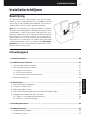
Table of Contents
1. Installation Information .........................................................................................................................3
2. Installing the System MMI Pack ............................................................................................................4
2.1 Installing the RF Receiver ..................................................................................................................4
2.2 Installing the Room Unit .....................................................................................................................5
2.2.1 Power Up ....................................................................................................................................5
2.2.2 RF Communication Check ..........................................................................................................5
2.2.3 Locating the Room Unit ..............................................................................................................6
2.3 Communication Loss .........................................................................................................................6
3. Installer Mode .........................................................................................................................................7
3.1 Entering Installer Mode ......................................................................................................................7
3.2 Fail-Safe Mode Setup ........................................................................................................................7
3.3
Using the Room Unit for Specific Applications ..................................................................................8
3.4
Using the Special Features of the Room Unit ....................................................................................8
3.5 Installer Parameters Table .................................................................................................................9
3.5.1 Category 1 - Room Unit Settings ................................................................................................9
3.5.2 Category 2 - System Settings ...................................................................................................10
4. Binding / Rebinding Procedure ...........................................................................................................11
5. Trouble Shooting ..................................................................................................................................12
5.1 Trouble Shooting Guide ...................................................................................................................12
5.2 Diagnostic Mode ..............................................................................................................................12
Installation and Operation Manual
Installation and Operation Manual

3
1. Installation Information
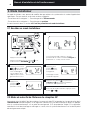
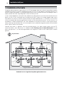
As these products communicate using RF technology special care must be taken during installation.
The location of the RF components as well as the building structure may influence performance of the
RF system. To assure system reliability, please review and apply the information given below.
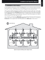
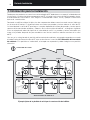
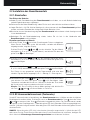
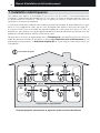
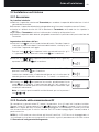
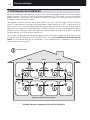
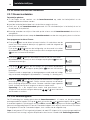
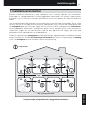
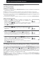
Within a typical residential building the two products should communicate reliably within a 30m range.
It is important to take into consideration that walls and ceilings will reduce the RF signal. The strength
of the RF signal reaching the RF Receiver depends on the number of walls and ceilings separating it
from the Room Unit, as well as the building construction - the diagram below illustrates an example of
typical signal strength reduction. Walls and ceilings reinforced with steel or plasterboard walls lined with
metal foil reduce the RF signal significantly more.
Once a position is selected for the Room Unit this can be checked using the RF Communication Test
mode as described in section 2.2.3 Locating the Room Unit on page 6. If the position is unsuitable the
RF Receiver will not respond and an alternative position for the Room Unit must be selected.
Typical example of Building Fabric Signal losses
Wall Wall Wall
Ceiling
Max. Signal Length 30 metres
= Signal Strength
Installation and Operation Manual
ΕΛΛΗΝΙΚΆ SVENSKA NEDERLANDS DANSK PORTUGUÊS ITALIANO FRANÇAIS DEUTSCH ESPAÑOL ENGLISH

4
2. Installing the System MMI Pack
Please follow the illustrations and information below in sequence to install the RF Receiver and Room
Unit correctly. To enable special features and see what other system options are available refer to section
3. Installer Mode.
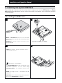
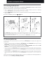
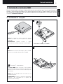
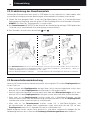
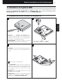
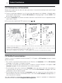
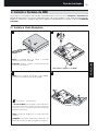
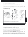
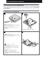
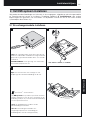
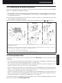
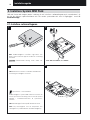
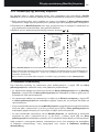
2.1 Installing the RF Receiver
1
NOTE: The RF Receiver contains no user serviceable
parts. It should be opened and installed by qualified
installer only.
WARNING: Electrostatic sensitive device! Do not touch
the circuit board.
NOTE: All wiring must be in accordance with IEE
regulations
CAUTION: Observe ambient temperature and current
limits (see the RF Receiver wiring label)
2
3 4
OpenTherm
®
- communication
The System MMI Pack can be connected to other
OpenTherm appliances. For the correct wiring
connections refer to the installation manual of the
OpenTherm device.
max. 30m. 2 x 0.5mm
2
; 2 x 0.8mm
2
Installation and Operation Manual
NOTE: For receiver and unit connection refer to
unit installation manual.

5
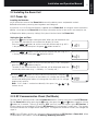
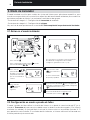
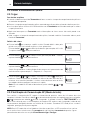
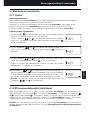
2.2.2 RF Communication Check (Test Mode)
To check the RF communication, hold the Room Unit about 2-3 metres from the installed RF Receiver.
Set the Room Unit to off by pressing the button. then press the and buttons together with the
button for 3 seconds. The unit will display ‘tESt’ and it will send test signals to the RF Receiver. If
the test signals are received the LED on the RF Receiver will flash between 1 and 5 times. The number
of flashes indicates the strength of the radio signal. The higher the number of flashes, the stronger the
signal is.
NOTE: If the LED does not flash or if you are installing a replacement RF Receiver or Room Unit, follow
the procedures described in section 4. Binding / Rebinding Procedure.
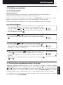
2.2 Installing the Room Unit
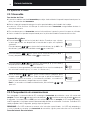
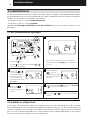
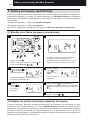
2.2.1 Power Up
Installing the Batteries:
a. Lift up the front cover of the Room Unit to reveal the battery cover and product controls.
b. Remove the battery cover by pressing down and sliding out.
c.
Insert the 2 x AA LR6 Alkaline Batteries supplied with the Room Unit, ensuring the correct orientation.
d. After a short pause the Room Unit will display information on the screen and is now ready for use.
e. Replace the battery cover by sliding it firmly back into the front of the Room Unit.
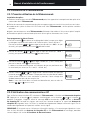
Setting the Date and Time:
a. Press the
button to begin setting the date. When you set the date for the
first time after the batteries are inserted, the display will show:
Press the
or buttons to set the current day of the month (e.g. d 01 =
1
st
day of the month) then press the green button to confirm.
b. Press the
or buttons to set the current month of the year (e.g. m 01
= January) then press the green button to confirm.
c. Press the
or buttons to set the current year (e.g. yr 09 = 2009) then
press the green button to confirm.
The date is now stored and the Day Indicator will be displayed under the
current day of the week (e.g. 1 = Monday, 2 = Tuesday, etc.)
d. Use the
or buttons to set the correct time then press the green
button to confirm. Each press of the buttons will change the time by one
minute and holding them down will change the time slowly at first and get
progressively quicker.
Note: If this mode is entered accidentally then press the
, or
buttons to exit.
AM
Installation and Operation Manual
ΕΛΛΗΝΙΚΆ SVENSKA NEDERLANDS DANSK PORTUGUÊS ITALIANO FRANÇAIS DEUTSCH ESPAÑOL ENGLISH

6
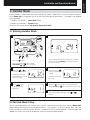
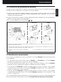
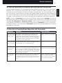
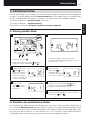
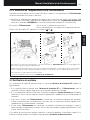
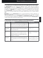
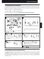
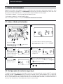
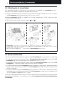
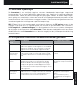
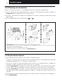
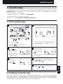
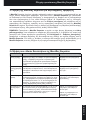
2.2.3 Locating the Room Unit
While still in the Test Mode, as described in section 2.2.2, the Room Unit should be located taking the
following into consideration and reviewing the illustrations below:
1. Find a suitable location where the signal transmission is reliable. Reliable transmission is indicated
when the RF Receiver is flashing the green LED every 6 seconds.
2. Install the Room Unit EITHER on the wall using the wall bracket OR attach the optional table stand as
shown in below.
3. Exit the Test Mode by pressing the
or button.
Wall bracket Table stand
•TheRoom Unit should be installed in an open space for best performance as it is a radio frequency device.
•
Leave at least 30cm distance from any metal objects including wall boxes and at least 1 metre from any other
electrical equipment eg. radio, TV, PC etc.
•Donotmountontometalwallboxes.•ItisrecommendedthattheRF Receiver is fully installed.
2.3 Communication Loss
In the event of an RF communications loss, the LED on the RF Receiver will indicate which type of fault
has occurred.
• IfthereisacommunicationsfaultbetweentheRF Receiver and the Room Unit, then the LED on the
RF Receiver will flash red for 0.1 sec ON every three seconds
• IfthereisafaultincommunicationsbetweentheboilerorSystem Controller, then the LED on the RF
Receiver will flash 3 times quickly and then be off for three seconds,
• IfthereismorethanoneRoom Unit installed, as in multi-zone systems for example, and communications
is lost with one zone, then the red LED on the RF Receiver will flash two times quickly and then be off
for two seconds.
• IfthereismorethanoneRoom Unit installed, as in multi-zone systems for example, and communications
is lost with both zones, then the red LED on the RF Receiver will flash once for 0.1 sec ON, and 0.9 sec
OFF.
Once the faulty device has been identified, replace as necessary and follow the re-binding procedure as
described in section 4. Binding / Rebinding Procedure.
Installation and Operation Manual
1.2-1.5m

7
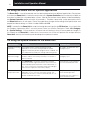
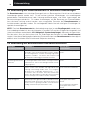
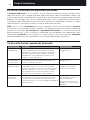
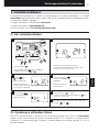
3.1 Entering Installer Mode
3.2 Fail-Safe Mode Setup
The fail-safe mode defines the system status if the RF communication is lost (e.g. when the Room Unit
stops communicating due to discharged batteries). If the system is a direct (radiator one), then the
factory setting will make the system revert to a set point of 10°C for frost protection. If indirect loops are
added, the system will continue to operate at the last communicated setpoint.
3. Installer Mode
Installer Mode is used to alter the system settings for specific applications, to use the special features
of the Room Unit in a different way or to alter the factory preset parameters. Parameters are divided
into two groups:
- Category 1 parameters – Room Unit Setup
- Category 2 parameters – System Setup.
These are all listed in section 3.5 Installer Parameters Table.
Press the button.
Press and hold the
button and the
PROGRAM & buttons together.
Press the
or to
change factory setting.
The display will flash
indicating that a change
has been made.
Press the green
button to confirm the
change.
The display will stop
flashing.
Press the
button to go to Installer parameter
group category 2 (
) (from Parameter n.4 to n.14).
To exit the installer mode press the
or
buttons.
Press
button
to go to the next
parameter.
The unit will display the first parameter of installer
parameter group category 1 (from Parameter n.1
to n.19) as shown
1 2
3 4
5 6
7
1..6
MANAUTO
1 2 3 4 5 6 7
1
2
2
ENGLISH
Installation and Operation Manual
ΕΛΛΗΝΙΚΆ SVENSKA NEDERLANDS DANSK PORTUGUÊS ITALIANO FRANÇAIS DEUTSCH ESPAÑOL ENGLISH

8
3.3 Using the Room Unit for Specic Applications
The Room Unit is a versatile controller that can be used to control many different applications. Please note
that when the Room Unit is installed in conjunction with a System Controller, the functionality will differ to
that when installed with a standard boiler system. Most of the functions shown below will be controlled by
the System Controller and be set within its parameters. Therefore, some of the system parameters within
the Room Unit menu will not apply. Please also note other changes to the setting of the optimisation and
proportional band settings as shown in tables 3.5.1 and 3.5.2.
NOTE: In order for the Room Unit to send the heating demand signal to the RF Receiver, it is essential that
the Category 2 parameter 8:Su is set to the correct value (see Installer Parameters Table, 3.5.2 Category
2 – System Settings). Failure to do this will mean that the heating system will not respond to changes in
the setpoint on the Room Unit. Under these circumstances the system will operate with no input from the
Room Unit and may not therefore provide adequate temperature control.
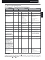
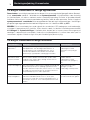
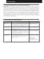
3.4 Using the Special Features of the Room Unit
Special Feature: Description: Enable/Disable
Heating or Cooling
Operation
This product can be used for heating or cooling
applications. If you select cooling mode the control
algorithm and factory default program will be modified. You
can independently modify the heating and cooling profile.
To enable: Set parameter 4:HC
(category 2) to 1.
Summer/Winter
Auto time change
This feature moves time automatically on the last Sunday
of March and the last Sunday of October. The feature is
factory enabled.
To enable: Set parameter 3:tC
(category 1) to 1.
Temperature Offset If the Room Unit is located in a particularly hot/cold
location for reliable signal transmission reasons then the
measured/displayed temperature can be adjusted by +/-
3°C. This is useful if the homeowner wants the reading to
match another appliance temperature display.
Set parameter 12:tO (category
1) to the required offset value.
Upper/Lower
Temperature Limit
The normal upper temperature limit of 35°C can be
reduced to 21°C to save the homeowner energy. The
normal lower limit of 5°C can be increased up to 21°C to
protect inhabitants from cold.
Set parameter 6:uL (category 1)
to the desired upper limit.
Set parameter 7:LL (category 1)
to the desired lower limit.
Installation and Operation Manual

9
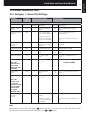
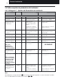
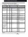
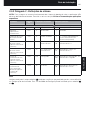
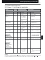
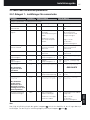
3.5 Installer Parameters Table
3.5.1 Category 1 - Room Unit Settings
Note
Remember to always press the green
button to confirm that you want to store your new Installer
Set-Up setting. To exit the Installer Mode press the or button.
Parameter Parameter
No.
Factory Default Setting Optional Setting
Category 1 Parameters – Room Unit Settings
Display Description Display Description
AM-PM / 24hr
Display
1:CL 24 24 hr clock display
format
12 12 hr – AM/PM clock display
format
Reset Time/ Temp
Program
2:rP 1 Time / Temp profile
set to factory default
Changes to 0 when
one of the time/temp
profiles are changed
0 Time / Temperature are as
programmed
To restore the factory profile set
to 1
Auto Summer/
Winter Time
Change
3:tC 1 Auto Summer/
Winter Time Change
Enabled
0 Auto Summer/Winter Time Change
Disabled
LCD Backlighting 5:bL 1 Backlighting Enable 0 Backlighting Disabled
Upper Temp Limit 6:uL 35 35°C Upper Temp.
Limit
21 to
34
21°C to 34°C adjustment in 1°C
steps
Lower Temp Limit 7:LL 5 5°C Lower Temp.
Limit
5 to 21 6°C to 21°C adjustment in 1°C
steps
Optimisation
Note: This
parameter will
not function
with the System
Controller.
8:OP 0 Optimisation
Disabled
1 Optimisation Enabled
DO NOT CHANGE
Temperature
Offset
12:tO 0 No temperature
offset
-3 to
+3
-3°C to +3°C adjustment in 0.1°C
steps
Proportional Band
Width
Note: This
function is for
use with the
extension system
only. It will not
function with
the System
Controller alone
13:Pb 1.5 Proportional band of
1.5 degrees
1.6 to
3.0
1.6°C to 3.0°C adjustment in 0.1°C
steps
Reset Parameters
to Factory
Defaults
19:FS 1 All settings at factory
defaults
Changes to 0 when
one of the parameter
is changed
0 Settings are as modified above
To restore the factory profile set
to 1
Installation and Operation Manual
ΕΛΛΗΝΙΚΆ SVENSKA NEDERLANDS DANSK PORTUGUÊS ITALIANO FRANÇAIS DEUTSCH ESPAÑOL ENGLISH

10
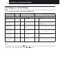
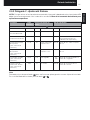
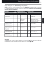
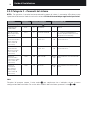
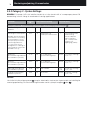
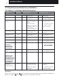
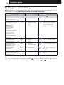
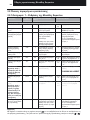
3.5.2 Category 2 - System Settings
NOTE: To ensure correct heat pump system operation, parameter 8:Su must be set correctly. See note in
section 3.3 Using the Room Unit for Specic Applications.
Note
Remember to always press the green
button to confirm that you want to store your new Installer Set-Up
setting. To exit the Installer Mode press the or button.
Parameter Parameter
No.
Factory Default Setting Optional Setting
Category 2 Parameters – System Settings (press the
button to access this category)
Heat/Cool selection
enable / disable
4:HC 0 Disabled 1 Enabled
Room Temperature
Sensor Use
8:Su 0
Programmer and
room compensation
unit
1
Programmer only. Transmits demand
and room setpoint (no temperature
displayed)
Maximum Flow
Setpoint (extension
systems only)
11:uF 55
55°C Maximum Flow
Temp.
0 to 99 0°C to 99°C adjustment in 1°C steps
Minimum Flow
Setpoint (extension
systems only)
12:LF 15
15°C Minimum Flow
Temp.
0 to 50 0°C to 50°C adjustment in 1°C steps
Mixing Value Run
Time (extension
systems only)
13:Ar 150 150 seconds
0 to
240
0 to 240 sec. adjustment in 1sec
steps
Pump Overrun Run
Time (extension
systems only)
14:Pr 15 15 minutes 0 to 99 0 to 99 mins adjustment in 1min steps
Installation and Operation Manual

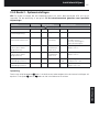
11
4. Binding / Rebinding Procedure
NOTE: For binding / Rebinding procedure refer to unit installation manual.
Installation and Operation Manual
ΕΛΛΗΝΙΚΆ SVENSKA NEDERLANDS DANSK PORTUGUÊS ITALIANO FRANÇAIS DEUTSCH ESPAÑOL ENGLISH

12
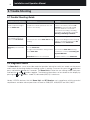
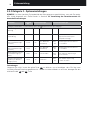
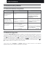
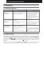
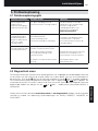
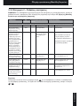
5. Trouble Shooting
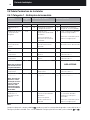
5.1 Trouble Shooting Guide
Symptom (Fault Message) Possible Cause Remedy
The RF Receiver does not
react to setpoint changes
on the Room Unit.
The Room Unit and RF Receiver are not
bound or the installer parameter 8:Su has
not been set correctly.
Make sure that the 8:Su parameter
value is set correctly. Reset the RF
Receiver by pressing and holding
the push button for 15 seconds.
Then follow the binding / rebinding
procedure as described in section 4.
Binding / Rebinding Procedure.
After the binding procedure
the red LED continues to
flash on the RF Receiver.
Incorrect or incomplete binding procedure.
Incorrect position of the Room Unit during
binding.
Repeat the binding procedure.
Repeat the binding procedure keeping
approx. 1m distance between the RF
Receiver and the Room Unit.
The red LED is on the RF
Receiver (Communication
loss)
The RF Receiver receives no RF messages
from the Room Unit:
RF signal is blocked due to wrong location
of the Room Unit.
Room Unit batteries are exhausted.
Re-locate the Room Unit following
instructions in section 2. Installing the
System MMI Pack.
Replace batteries in the Room Unit.
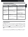
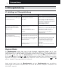
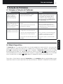
5.2 Diagnostic Mode
The Room Unit has a user accessible mode that provides information useful to a remote service person
and a means of checking whether the heating system is working. To access this press the button then
press and hold the button for 5 seconds. The Room Unit will enter the user settings mode. Next press
and hold the and buttons together. The following information can be viewed on the display by
pressing the or buttons : model ID, date code (WW/YY) & checksum.
Hereby, HITACHI declares that this Room Unit and RF Receiver are in compliance with the essential
requirements and other relevant provisions of Directive 1999/5/EC, 2006/95/EC and 2004/108/EC.
Installation and Operation Manual

13
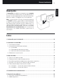
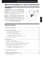
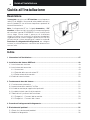
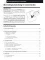
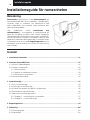
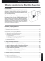
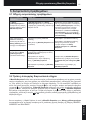
Descripción
El termostato de ambiente se comunica con el receptor
en una banda de radiofrecuencia (RF) de 868 MHz para
controlar un solo componente del sistema de calefacción,
como una caldera, una bomba o una válvula de zona.
Nota: La comunicación RF entre el termostato ambiente
y el receptor en packs suministrados está preconfigurada
en fábrica y por ello DEBEN instalarse juntos. Esto hace
que el proceso de instalación sea fácil y rápido. Pero si se
separan productos de packs individuales, o si se mezclan
con otros packs preconfigurados, consulte la sección 4.
Procedimiento de reconocimiento para sincronizar de
nuevo entre sí las unidades deseadas y permitir que se
comuniquen.
Índice
1. Información para la instalación ......................................................................................................14
2. Instalando el sistema MMI ...............................................................................................................15
2.1 Instalando el receptor ..................................................................................................................15
2.2 Instalando el termostato de ambiente .........................................................................................16
2.2.1 Encendido ............................................................................................................................16
2.2.2 Comprobación de comunicaciones .....................................................................................16
2.2.3 Ubicación del termostato de ambiente ................................................................................17
2.3 Pérdida de la comunicación ........................................................................................................17
3. Modo instalador ...............................................................................................................................18
3.1 Entrar en el modo instalador ........................................................................................................18
3.2 Configuración en modo a prueba de fallos .................................................................................18
3.3 Uso del termostato de ambiente para aplicaciones específicas ................................................19
3.4 Uso de las Características Especiales del Termostato ...............................................................19
3.5 Tabla completa de parámetros del instalador .............................................................................20
3.5.1 Categoría 1 - Ajustes del Termostato de ambiente ..............................................................20
3.5.2 Categoría 2 - Ajustes del Sistema ........................................................................................21
4. Procedimiento de reconocimiento .................................................................................................22
5. Resolución de problemas ...............................................................................................................23
5.1 Guía para la resolución de problemas ........................................................................................23
5.2 Modo diagnóstico ........................................................................................................................23
Guía de Instalación
ΕΛΛΗΝΙΚΆ SVENSKA NEDERLANDS DANSK PORTUGUÊS ITALIANO FRANÇAIS DEUTSCH ESPAÑOL ENGLISH

14
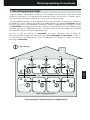
1. Información para la instalación
Dado que estos productos se comunican con tecnología de RF, debe tenerse un especial cuidado durante
la instalación. La ubicación de los componentes de RF así como la estructura del edificio pueden afectar
el rendimiento del sistema de RF. Para asegurar la fiabilidad del sistema, revise y aplique la información
que se da a continuación.
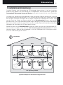
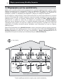
Dentro de un edificio residencial típico, los dos componentes deben comunicarse de manera fiable con
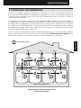
un alcance de 30 metros. Es importante tener en cuenta que paredes y techos reducen la señal de RF.
La intensidad de la señal de RF que llega al receptor depende del número de paredes y techos que le
separan del termostato de ambiente y, además, de la construcción del edificio – el diagrama siguiente
ilustra un ejemplo de reducción típica de la intensidad de señal. Las paredes y techos reforzados con
acero o las paredes de panel de yeso recubiertas con láminas metálicas reducen mucho más la señal
de RF.
Una vez se ha seleccionado la posición del termostato de ambiente, esto puede comprobarse usando
el modo Prueba de Comunicación de RF, que se describe en la sección 2.2.3 Ubicación del termostato
de ambiente. Si la posición es inadecuada, el receptor no responderá y deberá elegirse una posición
alternativa.
Ejemplo típico de la pérdida de señal por la construcción del edicio
Pared Pared Pared
Techo
Alcance máximo de señal 30 m.
= Intensidad de la señal
Guía de Instalación

15
2. Instalando el sistema MMI
Siga la secuencia de ilustraciones e información que hay más adelante para instalar correctamente el
receptor y el termostato de ambiente. Para aplicaciones distintas de una caldera de gas, para activar
las características especiales y para ver qué otras opciones están disponibles en el sistema, consulte
la sección 3. Modo de Instalador.
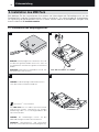
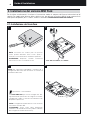
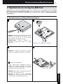
2.1 Instalando el receptor
NOTA: El receptor no contiene elementos para el
usuario. Sólo debe abrirlo e instalarlo un instalador
cualificado.
ADVERTENCIA: ¡Aparato sensible a cargas
electrostáticas! No toque la tarjeta de circuito impreso.
NOTA: Todo el cableado debe ser acorde con las
normativas locales.
PRECAUCIÓN: Observe los límites de temperatura
ambiente y de intensidad (vea la etiqueta de
conexiones del receptor)
1 2
3 4
OpenTherm
®
- communication
El sistema MMI puede conectarse a otros aparatos
OpenTherm. Para ver las conexiones correctas de ca-
bleado consulte el manual de instalación del dispositivo
OpenTherm.
max. 30m. 2 x 0.5mm
2
; 2 x 0.8mm
2
Guía de Instalación
ΕΛΛΗΝΙΚΆ SVENSKA NEDERLANDS DANSK PORTUGUÊS ITALIANO FRANÇAIS DEUTSCH ESPAÑOL ENGLISH
NOTA: Para la conexión del receptor y de la unidad
consulte el manual de instalación de la unidad

16
2.2 Ajuste de la fecha
2.2.1 Encendido
Para instalar las Pilas:
a. Levante la cubierta frontal del termostato para dejar al descubierto la tapa del compartimento para las
pilas y los controles del termostato.
b. Retire la tapa del compartimento para las pilas presionándola y deslizándola hacia abajo .
c. Inserte las 2 Pilas Alcalinas AA LR6 que se suministran con el termostato, asegurándose de tener la
orientación correcta.
d.
Tras una breve pausa, el termostato mostrará información en la pantalla y estará listo para ser utilizado.
e. Vuelva a colocar la tapa del compartimento para las pilas deslizándola firmemente hacia arriba.
Ajuste del Día y la Hora
a. Pulse el botón
para iniciar el ajuste de la fecha. Cuando se vaya a ajustar
la fecha por primera vez después de la inserción de las pilas, en la pantalla
aparecerá:
Pulse los botones
o para ajustar el día actual del mes (p. ej. d 01 = 1er
día del mes) y después pulse el botón verde para confirmar.
b. Pulse los botones
o para ajustar el mes actual del año (p. ej. m 01 =
Enero) y después pulse el botón verde
para confirmar.
c. Pulse los botones
o para ajustar el año actual (p. ej. yr 09 = 2009) y
después pulse el botón verde para confirmar.
La fecha está ahora guardada y el Indicador de Día se visualizará debajo del
día actual de la semana (p. ej. 1= Lunes, 2 = Martes, etc.)
d. Utilice los botones
o para ajustar la hora correcta y después pulse
el botón verde para confirmar. Cada vez que se pulsen los botones se
cambiará la hora en un minuto, y al mantenerlas pulsadas, se cambiará la
hora, primero lentamente y luego cada vez más rápido.
Nota: si se accede a este modo accidentalmente, pulse el botón
, u
para salir.
2.2.2 Comprobación de comunicaciones
Para comprobar la comunicación de RF, mantenga el termostato de ambiente a unos 2-3 metros del
receptor. Pulse el botón y después pulse los botones y simultáneamente con el botón durante
3 segundos. La unidad mostrará tESt y enviará señales de prueba al receptor, el LED verde parpadeará
cada 5 segundos ( el relé permanecerá desconectado) durante un máximo de 10 minutos. Cuando el LED
verde parpadee cada 5 segundos, prosiga al paso siguiente.
REMARQUE : Si el LED verde no se conecta a los intervalos especificados, si el LED rojo parpadea, o
si está instalando un receptor o un termostato de recambio, siga los pasos descritos en la sección 5.1
Procedimiento de Reconocimiento.
AM
Guía de Instalación

17
2.2.3 Ubicación del termostato de ambiente
Estando aún en el modo TEST, tal como se ha descrito, debe situarse el termostato de ambiente
teniendo en cuenta lo siguiente y revisando las ilustraciones debajo:
1. Encuentre una ubicación aceptable, donde la transmisión de la señal sea fiable. Una transmisión
fiable se indica por el LED verde del receptor parpadeando cada 5 segundos. NOTA: El relé del
receptor estará desconectado.
2. Instale el termostato en la pared, usando el soporte de pared o colóquelo en el pie de sobremesa
opcional, tal como indica la ilustración debajo.
3. Para salir del modo de
TEST,
pulse el botón o .
2.3 Pérdida de la comunicación
En el caso de una pérdida de la comunicación de RF, el LED del Receptor indicará qué tipo de fallo
se ha producido.
• En caso de fallo de comunicaciones entre el Receptor y la Termostato, el LED del Receptor
parpadeará en rojo durante 0,1 seg en ON cada tres segundos.
• EncasodefallodecomunicacionesentrelacalderaoelSystemController,elLEDdelReceptor
parpadeará 3 veces rápidamente y después se apagará durante tres segundos.
• SihaymásdeunaTermostato instalada, como por ejemplo en sistemas multizona, y se ha perdido
la comunicación con una zona, el LED rojo del Receptor parpadeará dos veces rápidamente y
después se apagará durante dos segundos.
• SihaymásdeunaTermostato instalada, como por ejemplo en sistemas multizona, y se ha perdido
la comunicación con ambas zonas, el LED rojo del Receptor parpadeará una vez durante 0,1 seg
en ON y 0,9 seg en OFF.
Una vez identificado el dispositivo defectuoso, sustitúyalo según sea necesario y siga el procedimiento
de revinculación que se describe en la sección 4. Procedimiento de vinculación / revinculación.
Socle mural Support
•Eltermostatodeambientedebeestarinstaladoenunespacioabiertoparasumejorfuncionamiento,yaquees
un dispositivo de radio frecuencia.
•Dejeunadistanciamínimade30cm.decualquierobjetometálico,incluyendocajasempotradas,yporlomenos
1 metro de otros equipos eléctricos como radio, TV, PC, etc.
•Nolomontesobrecajasmetálicasempotradas.•Serecomiendaqueelreceptorestétotalmente
instalado.
Guía de Instalación
ΕΛΛΗΝΙΚΆ SVENSKA NEDERLANDS DANSK PORTUGUÊS ITALIANO FRANÇAIS DEUTSCH ESPAÑOL ENGLISH

18
3.1 Entrar en el modo instalador
3.2 Conguración en modo a prueba de fallos
El modo a prueba de fallos define la situación del sistema si se pierde la comunicación de RF (p. ej.
cuando la Termostato deja de comunicar debido a que las baterías están descargadas). Si el sistema
es directo (un radiador), el ajuste de fábrica hará que el sistema revierta a un punto de ajuste de 10 ºC
para protección contra heladas. Si se añaden bucles indirectos, el sistema continuará funcionando con
el último punto de ajuste comunicado.
3. Modo de Instalador
El modo instalador se utiliza para cambiar los ajustes del sistema para aplicaciones específicas, para
usar de una manera distinta las características especiales del termostato de ambiente o para cambiar los
parámetros prefijados en fábrica. Los parámetros se dividen en dos grupos:
- Parámetros de categoría 1 – Configuración del termostato de ambiente
- Parámetros de categoría 2 – Configuración del sistema.
Hay una lista de estos parámetros en la sección 3.5 Tabla completa de los parámetros del instalador.
Pulse el botón .
Pulse y mantenga pulsado el botón
y los dos
botones PROGRAM y a la vez.
Pulse el botón
o
para cambiar el ajuste
de fábrica. La pantalla
parpadeará indicando
que se ha realizado un
cambio.
Pulse el botón verde
para confirmar el
cambio.
El valor seleccionado
dejará de parpadear.
Pulse el botón PROGRAM
para ir al grupo de
Modo del Configuración de Instalador, categoría 2
(
) (parámetros entre 1 y 10).
Para salir del Modo de Configuración de
Instalador, pulse el botón
u .
Pulse el botón
para pasar
al parámetro
siguiente.
En la pantalla se visualizará el primer parámetro
del Modo de Configuración de Instalador,
categoría 1 (parámetros entre 1 y 19)
1 2
3 4
5 6
7
1..6
MANAUTO
1 2 3 4 5 6 7
1
2
2
Guía de Instalación

19
3.3 Uso del termostato de ambiente para aplicaciones especícas
El termostato de ambiente es un controlador versátil que puede utilizarse para muchas aplicaciones
diferentes. Para la mayoría de aplicaciones típicas, como el control de calderas murales a gas o
el control de válvulas de zona, no se precisa ningún ajuste distinto a los ajustes de fábrica. Para
otras aplicaciones, como controlar una caldera de gasóleo, puede conseguirse el mejor rendimiento
del sistema modificando los parámetros seleccionados del termostato de ambiente en el modo de
instalador. La tabla siguiente lista los ajustes más habituales utilizados para aplicaciones específicas.
NOTA: Para que la Termostato envíe la señal de función de calentamiento al Receptor, es esencial
que el parámetro 8:Su de la categoría 2 esté ajustado al valor correcto (vea la Tabla de parámetros del
instalador, 3.5.2 Categoría 2 – Ajustes del sistema). Si no se hace así significará que el sistema de
calentamiento no responderá a cambios del punto de ajuste en la Termostato. En estas circunstancias
el sistema funcionará sin entrada desde la Termostato y, por lo tanto, no puede proporcionar un control
de temperatura adecuado.
3.4 Uso de las Características Especiales del Termostato
Característica
Especial
Descripción Activar / Desactivar
Funcionamiento de
Calefacción o Aire
Acondicionado
Este producto puede utilizarse para aplicaciones de
calefacción o aire acondicionado. Si selecciona el
modo de aire acondicionado, el algoritmo de control y el
programa de fábrica por defecto se verán modificados.
Usted puede modificar independientemente el perfil de
calefacción y aire acondicionado.
Ajuste 4: parámetro HC (categoría
2) a 1.
Cambio Automá-
tico de la Hora de
Verano / Invierno
Esta característica cambia la hora automáticamente el úl-
timo domingo de marzo y el último domingo de octubre.
La característica viene activada de fábrica.
Ajuste 3: parámetro tC (categoría
1) a 1.
Desviación
permanente de la
Temperatura
Si el termostato se encuentra en un lugar especialmente
caliente / frío y no puede desplazarse debido al cablea-
do, la temperatura medida / visualizada puede ajustarse
en +/- 3ºC. Esto es útil si el propietario de la casa quiere
que la lectura se corresponda con la visualización de
temperatura de otro aparato.
Ajuste 12: parámetro tO (categoría
1) al valor de variación requerido.
Límite de Tempe-
ratura Superior /
Inferior
El límite superior de temperatura de 35ºC puede reducir-
se a 21ºC para que el propietario de la casa ahorre
energía. El límite inferior de 5ºC puede aumentarse hasta
21ºC para proteger a los ocupantes de la casa contra
el frío.
Ajuste 6: parámetro uL (categoría
1) al límite superior deseado.
Ajuste 7: parámetro LL (categoría
1) al límite inferior deseado.
Guía de Instalación
ΕΛΛΗΝΙΚΆ SVENSKA NEDERLANDS DANSK PORTUGUÊS ITALIANO FRANÇAIS DEUTSCH ESPAÑOL ENGLISH

20
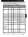
3.5 Tabla completa de parámetros del instalador
3.5.1 Categoría 1 - Ajustes del Termostato de ambiente
Nota
Recuerde pulsar siempre el botón
para confirmar que quiere guardar su nuevo Ajuste de Instalador.
Para salir del Modo de Instalador, pulse el botón
o
.
Parámetro Nº de
Parámetro
Ajustes por Defecto de Fábrica Ajustes Opcionales
Parámetros de la Categoría 1 - Ajustes del Termostato de ambiente
Pantalla
Descripción
Pantalla
Descripción
Visualización AM-PM
/ 24 horas
1:CL 24 Formato de visualización
de reloj de 24 horas
12 Formato de visualización de
reloj 12 horas – AM/PM
Reinicialización de
Programa de Horas /
Temperaturas
2:rP 1 Perfil de horas /
temperaturas ajustado
al valor por defecto de
fábrica
Cambia a 0 al cambiar
alguno de los perfiles de
horas / temperaturas
0 La hora / temperatura es la
programada
Para restablecer el perfil de
fábrica, ajuste a 1
Cambio Automático
de la Hora de Verano
/ Invierno
3:tC 1 Cambio Automático de la
Hora de Verano / Invierno
Activado
0 Cambio Automático de la
Hora de Verano / Invierno
Desactivado
Iluminación de Fondo
de pantalla LCD
5:bL 1 Activación de la
Iluminación de Fondo
0 Iluminación de Fondo
Desactivada
Límite de
Temperatura Máxima
6:uL 35 Límite de Temperatura
Máxima 35ºC
21 à
34
Ajuste de 21°C a 34ºC en
pasos de 1°C
Límite de
Temperatura Mínima
7:LL 5 Límite de Temperatura
Mínima 5ºC
5 à 21 Ajuste de 6ºC a 21°C en
pasos de 1°C
Optimización
Nota: Este
parámetro no
funcionará con el
Sistema Controlador.
8:OP 0 Optimización
Desactivada
1 Optimización activada
Desviación perma-
nente de la Tempe-
ratura
12:tO 0 Ninguna variación de
temperatura
-3 à
+3
Ajuste de -3°C a +3ºC en
pasos de 0,1°C
Amplitud de Banda
Proporcional
Nota: esta función
es para ser utilizada
sólo con el sistema
de extensión. No
funcionará con el
Sistema Controlador
individual.
13:Pb 1,5 Banda proporcional de
1,5 grados
1,6 à
3,0
Ajuste de 1,6°C a 3,0ºC en
pasos de 0,1°C
Reinicialización de
los Parámetros a los
Valores por Defecto
de Fábrica
19:FS 1 Todos los ajustes a los
valores por defecto de
fábrica
Cambia a 0 al cambiar
alguno de los parámetros
0 Los ajustes están según la
modificación anterior
Para restablecer el perfil de
fábrica, ajuste a 1
Guía de Instalación
NO CAMBIAR
Sidan laddas...
Sidan laddas...
Sidan laddas...
Sidan laddas...
Sidan laddas...
Sidan laddas...
Sidan laddas...
Sidan laddas...
Sidan laddas...
Sidan laddas...
Sidan laddas...
Sidan laddas...
Sidan laddas...
Sidan laddas...
Sidan laddas...
Sidan laddas...
Sidan laddas...
Sidan laddas...
Sidan laddas...
Sidan laddas...
Sidan laddas...
Sidan laddas...
Sidan laddas...
Sidan laddas...
Sidan laddas...
Sidan laddas...
Sidan laddas...
Sidan laddas...
Sidan laddas...
Sidan laddas...
Sidan laddas...
Sidan laddas...
Sidan laddas...
Sidan laddas...
Sidan laddas...
Sidan laddas...
Sidan laddas...
Sidan laddas...
Sidan laddas...
Sidan laddas...
Sidan laddas...
Sidan laddas...
Sidan laddas...
Sidan laddas...
Sidan laddas...
Sidan laddas...
Sidan laddas...
Sidan laddas...
Sidan laddas...
Sidan laddas...
Sidan laddas...
Sidan laddas...
Sidan laddas...
Sidan laddas...
Sidan laddas...
Sidan laddas...
Sidan laddas...
Sidan laddas...
Sidan laddas...
Sidan laddas...
Sidan laddas...
Sidan laddas...
Sidan laddas...
Sidan laddas...
Sidan laddas...
Sidan laddas...
Sidan laddas...
Sidan laddas...
Sidan laddas...
Sidan laddas...
Sidan laddas...
Sidan laddas...
Sidan laddas...
Sidan laddas...
Sidan laddas...
Sidan laddas...
Sidan laddas...
Sidan laddas...
Sidan laddas...
Sidan laddas...
Sidan laddas...
Sidan laddas...
Sidan laddas...
Sidan laddas...
Sidan laddas...
Sidan laddas...
Sidan laddas...
Sidan laddas...
Sidan laddas...
Sidan laddas...
Sidan laddas...
Sidan laddas...
-
 1
1
-
 2
2
-
 3
3
-
 4
4
-
 5
5
-
 6
6
-
 7
7
-
 8
8
-
 9
9
-
 10
10
-
 11
11
-
 12
12
-
 13
13
-
 14
14
-
 15
15
-
 16
16
-
 17
17
-
 18
18
-
 19
19
-
 20
20
-
 21
21
-
 22
22
-
 23
23
-
 24
24
-
 25
25
-
 26
26
-
 27
27
-
 28
28
-
 29
29
-
 30
30
-
 31
31
-
 32
32
-
 33
33
-
 34
34
-
 35
35
-
 36
36
-
 37
37
-
 38
38
-
 39
39
-
 40
40
-
 41
41
-
 42
42
-
 43
43
-
 44
44
-
 45
45
-
 46
46
-
 47
47
-
 48
48
-
 49
49
-
 50
50
-
 51
51
-
 52
52
-
 53
53
-
 54
54
-
 55
55
-
 56
56
-
 57
57
-
 58
58
-
 59
59
-
 60
60
-
 61
61
-
 62
62
-
 63
63
-
 64
64
-
 65
65
-
 66
66
-
 67
67
-
 68
68
-
 69
69
-
 70
70
-
 71
71
-
 72
72
-
 73
73
-
 74
74
-
 75
75
-
 76
76
-
 77
77
-
 78
78
-
 79
79
-
 80
80
-
 81
81
-
 82
82
-
 83
83
-
 84
84
-
 85
85
-
 86
86
-
 87
87
-
 88
88
-
 89
89
-
 90
90
-
 91
91
-
 92
92
-
 93
93
-
 94
94
-
 95
95
-
 96
96
-
 97
97
-
 98
98
-
 99
99
-
 100
100
-
 101
101
-
 102
102
-
 103
103
-
 104
104
-
 105
105
-
 106
106
-
 107
107
-
 108
108
-
 109
109
-
 110
110
-
 111
111
-
 112
112


på andra språk
- italiano: Hitachi ATW-RTU-02 Istruzioni per l'uso
- español: Hitachi ATW-RTU-02 Instrucciones de operación
- Deutsch: Hitachi ATW-RTU-02 Bedienungsanleitung
- português: Hitachi ATW-RTU-02 Instruções de operação
- français: Hitachi ATW-RTU-02 Mode d'emploi
- English: Hitachi ATW-RTU-02 Operating instructions
- dansk: Hitachi ATW-RTU-02 Betjeningsvejledning
- Nederlands: Hitachi ATW-RTU-02 Handleiding