Yamaha RX-V100D Bruksanvisning
- Kategori
- AV-mottagare
- Typ
- Bruksanvisning

YAMAHA ELECTRONICS CORPORATION, USA
6660 ORANGETHORPE AVE., BUENA PARK, CALIF. 90620, U.S.A.
YAMAHA CANADA MUSIC LTD.
135 MILNER AVE., SCARBOROUGH, ONTARIO M1S 3R1, CANADA
YAMAHA ELECTRONIK EUROPA G.m.b.H.
SIEMENSSTR. 22-34, 25462 RELLINGEN BEI HAMBURG, GERMANY
YAMAHA ELECTRONIQUE FRANCE S.A.
RUE AMBROISE CROIZAT BP70 CROISSY-BEAUBOURG 77312 MARNE-LA-VALLEE CEDEX02, FRANCE
YAMAHA ELECTRONICS (UK) LTD.
YAMAHA HOUSE, 200 RICKMANSWORTH ROAD WATFORD, HERTS WD18 7GQ, ENGLAND
YAMAHA SCANDINAVIA A.B.
J A WETTERGRENS GATA 1, BOX 30053, 400 43 VÄSTRA FRÖLUNDA, SWEDEN
YAMAHA MUSIC AUSTRALIA PTY, LTD.
17-33 MARKET ST., SOUTH MELBOURNE, 3205 VIC., AUSTRALIA
©
2005 All rights reserved.
RX-V100D
Printed in Malaysia WG22480
RX-V100D
AV Receiver
Ampli-tuner audio-vidéo
OWNER’S MANUAL
MODE D’EMPLOI
BEDIENUNGSANLEITUNG
G

CAUTION: READ THIS BEFORE OPERATING YOUR UNIT.
1 To assure the finest performance, please read this
manual carefully. Keep it in a safe place for future
reference.
2 Install this sound system in a well ventilated, cool,
dry, clean place – away from direct sunlight, heat
sources, vibration, dust, moisture, and/or cold.
Allow ventilation space of at least 30 cm on the top,
20 cm on the left and right, and 20 cm on the back of
this unit.
3 Locate this unit away from other electrical
appliances, motors, or transformers to avoid
humming sounds.
4 Do not expose this unit to sudden temperature
changes from cold to hot, and do not locate this unit
in a environment with high humidity (i.e. a room with
a humidifier) to prevent condensation inside this
unit, which may cause an electrical shock, fire,
damage to this unit, and/or personal injury.
5 Avoid installing this unit where foreign object may
fall onto this unit and/or this unit may be exposed to
liquid dripping or splashing. On the top of this unit,
do not place:
– Other components, as they may cause damage
and/or discoloration on the surface of this unit.
– Burning objects (i.e. candles), as they may cause
fire, damage to this unit, and/or personal injury.
– Containers with liquid in them, as they may fall
and liquid may cause electrical shock to the user
and/or damage to this unit.
6 Do not cover this unit with a newspaper, tablecloth,
curtain, etc. in order not to obstruct heat radiation. If
the temperature inside this unit rises, it may cause
fire, damage to this unit, and/or personal injury.
7 Do not plug in this unit to a wall outlet until all
connections are complete.
8 Do not operate this unit upside-down. It may
overheat, possibly causing damage.
9 Do not use force on switches, knobs and/or cords.
10 When disconnecting the power cord from the wall
outlet, grasp the plug; do not pull the cord.
11 Do not clean this unit with chemical solvents; this
might damage the finish. Use a clean, dry cloth.
12 Only voltage specified on this unit must be used.
Using this unit with a higher voltage than specified
is dangerous and may cause fire, damage to this
unit, and/or personal injury. YAMAHA will not be
held responsible for any damage resulting from use
of this unit with a voltage other than specified.
13 To prevent damage by lightning, keep the power
cord and outdoor antennas disconnected from a
wall outlet or the unit during a lightning storm.
14 Do not attempt to modify or fix this unit. Contact
qualified YAMAHA service personnel when any
service is needed. The cabinet should never be
opened for any reasons.
15 When not planning to use this unit for long periods
of time (i.e. vacation), disconnect the AC power plug
from the wall outlet.
16 Be sure to read the “TROUBLESHOOTING” section
on common operating errors before concluding that
this unit is faulty.
17 Before moving this unit, press STANDBY/ON to set
this unit in the standby mode, and disconnect the
AC power plug from the wall outlet.
18 Install this unit near the AC outlet and where the AC
power plug can be reached easily.
■ For U.K. customers
If the socket outlets in the home are not suitable for the
plug supplied with this appliance, it should be cut off and
an appropriate 3 pin plug fitted. For details, refer to the
instructions described below.
The plug severed from the mains lead must be destroyed, as a
plug with bared flexible cord is hazardous if engaged in a live
socket outlet.
■ Special Instructions for U.K. Model
CAUTION: READ THIS BEFORE OPERATING YOUR UNIT.
WARNING
TO REDUCE THE RISK OF FIRE OR ELECTRIC
SHOCK, DO NOT EXPOSE THIS UNIT TO RAIN
OR MOISTURE.
This unit is not disconnected from the AC power
source as long as it is connected to the wall outlet,
even if this unit itself is turned off. This state is called
the standby mode. In this state, this unit is designed to
consume a very small quantity of power.
Note
IMPORTANT
THE WIRES IN MAINS LEAD ARE COLOURED IN
ACCORDANCE WITH THE FOLLOWING CODE:
Blue: NEUTRAL
Brown: LIVE
As the colours of the wires in the mains lead of this
apparatus may not correspond with the coloured
markings identifying the terminals in your plug,
proceed as follows:
The wire which is coloured BLUE must be connected
to the terminal which is marked with the letter N or
coloured BLACK. The wire which is coloured
BROWN must be connected to the terminal which is
marked with the letter L or coloured RED.
Making sure that neither core is connected to the earth
terminal of the three pin plug.

1
PREPARATIONINTRODUCTION
BASIC
OPERATION
SOUND FIELD
PROGRAMS
ADVANCED
OPERATION
ADDITIONAL
INFORMATION
English
FEATURES............................................................. 2
GETTING STARTED............................................ 3
Supplied accessories .................................................. 3
Installing batteries in the remote control ................... 3
CONTROLS AND FUNCTIONS ......................... 4
Front panel ................................................................. 4
Remote control........................................................... 6
Using the remote control ........................................... 7
Front panel display .................................................... 8
Rear panel ................................................................ 10
SPEAKER SETUP ............................................... 11
Speaker placement ................................................... 11
Speaker connections ................................................ 12
Speaker impedance setting ...................................... 14
CONNECTING AUDIO AND VIDEO
COMPONENTS ............................................... 15
Before connecting components................................ 15
Connecting video components................................. 16
Connecting audio components................................. 19
Connecting the FM and AM antennas ..................... 20
Connecting the DAB antenna .................................. 21
Connecting the power supply cord .......................... 21
Turning on the power............................................... 21
BASIC SETUP ...................................................... 22
Using the BASIC SETUP menu .............................. 22
PLAYBACK.......................................................... 25
Basic operations....................................................... 25
Selecting sound field programs ............................... 27
Selecting input modes.............................................. 31
FM/AM TUNING ................................................. 33
Automatic and manual tuning.................................. 33
Presetting stations .................................................... 34
Selecting preset stations........................................... 36
Exchanging preset stations ...................................... 37
Receiving Radio Data System stations .................... 38
Changing the Radio Data System mode .................. 39
PTY SEEK function ................................................ 40
EON function........................................................... 41
DAB (DIGITAL AUDIO BROADCASTING)... 42
About DAB.............................................................. 42
DAB tuning.............................................................. 43
PRESET MEMORY ................................................ 44
DAB service information......................................... 46
Accessing DAB MENU........................................... 47
INIT SCAN.............................................................. 47
TUNE AID............................................................... 48
Dynamic Range Control .......................................... 49
PRUNE LIST........................................................... 50
PRESET DELETE................................................... 50
RECORDING ....................................................... 51
SOUND FIELD
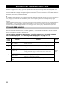
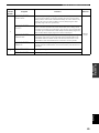
PROGRAM DESCRIPTIONS.........................52
For movie/video sources.......................................... 52
For music sources .................................................... 54
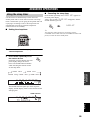
ADVANCED OPERATIONS ..............................55
Using the sleep timer ............................................... 55
Manually adjusting speaker levels........................... 56
SET MENU ............................................................57
Using SET MENU ................................................... 58
1 SOUND MENU.................................................... 59
2 INPUT MENU...................................................... 61
3 DAB MENU ......................................................... 62
4 OPTION MENU................................................... 63
ADVANCED SETUP MENU...............................64
REMOTE CONTROL FEATURES ...................66
Control area ............................................................. 66
Setting remote control codes ................................... 67
Controlling other components ................................. 68
EDITING SOUND FIELD PARAMETERS ......69
What is a sound field ............................................... 69
Changing parameter settings ................................... 69
SOUND FIELD PARAMETER
DESCRIPTIONS...............................................71
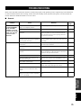
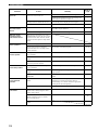
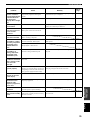
TROUBLESHOOTING .......................................73
RESETTING THE FACTORY PRESETS ........78
GLOSSARY...........................................................79
Audio formats .......................................................... 79
Sound field programs............................................... 80
Audio information ................................................... 80
Video signal information ......................................... 81
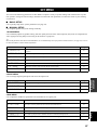
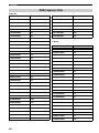
DAB Frequency Table............................................. 82
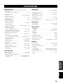
SPECIFICATIONS...............................................83
CONTENTS
INTRODUCTION
PREPARATION
BASIC OPERATION
SOUND FIELD PROGRAMS
ADVANCED OPERATION
ADDITIONAL INFORMATION

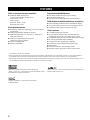
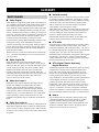
FEATURES
2
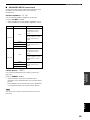
Built-in 6-channel power amplifier
◆ Minimum RMS output power
(0.06% THD, 20 Hz to 20 kHz, 8 Ω)
Front: 85 W + 85 W
Center: 85 W
Surround: 85 W + 85 W
Surround back: 85 W
Sound field features
◆ Proprietary YAMAHA technology for the creation of
sound fields
◆ Dolby Digital/Dolby Digital EX decoder
◆ DTS/DTS-ES Matrix 6.1, Discrete 6.1, DTS Neo:6,
DTS 96/24 decoder
◆ Dolby Pro Logic/Dolby Pro Logic II/
Dolby Pro Logic IIx decoder
◆ Virtual CINEMA DSP
◆ SILENT CINEMA
™
Sophisticated AM/FM tuner
◆ 40-station random and direct preset tuning
◆ Automatic preset tuning
◆ Preset station shifting capability (preset editing)
DAB (Digital Audio Broadcasting reception)
◆ DLS (Dynamic Label Segment) information display
◆
Locate all DAB services in your area using INIT SCAN
◆ Optimize DAB reception using TUNE AID
Other features
◆ 192-kHz/24-bit D/A converter
◆ A SET MENU that provides you with items for
optimizing this unit for your audio/video system
◆ 6 additional input jacks for discrete multi-channel input
◆ S-video signal input/output capability
◆ Component video input/output capability
◆ Optical and coaxial digital audio signal jacks
◆ Sleep timer
◆ Cinema and music night listening modes
◆ Remote control with preset remote control codes
• y indicates a tip for your operation.
• Some operations can be performed by using either the buttons on the main unit or on the remote control. In cases when the button
names differ between the main unit and the remote control, the button name on the remote control is given in parentheses.
• This manual is printed prior to production. Design and specifications are subject to change in part as a result of improvements, etc. In
case of differences between the manual and product, the product has priority.
Manufactured under license from Dolby Laboratories.
“Dolby”, “Pro Logic”, “Surround EX”, and the double-D symbol
are trademarks of Dolby Laboratories.
“SILENT CINEMA” is a trademark of YAMAHA
CORPORATION.
“DTS”, “DTS-ES”, “Neo:6” and “DTS 96/24” are trademarks of
Digital Theater Systems, Inc.
FEATURES

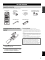
GETTING STARTED
3
INTRODUCTION
English
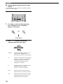
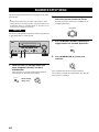
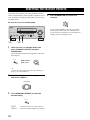
Please check that you received all of the following parts.
1 Press the part and slide the battery
compartment cover off.
2 Insert two supplied batteries (AA, R06, UM-3)
according to the polarity markings (+ / –) on
the inside of the battery compartment.
3 Slide the cover back until it snaps into place.
Notes on batteries
• Do not use old batteries together with new ones.
• Do not use different types of batteries (such as alkaline and
manganese batteries) together. Read the packaging carefully as
these different types of batteries may have the same shape and
color.
• If the batteries have leaked, dispose of them immediately. Avoid
touching the leaked material or letting it come into contact with
clothing, etc. Clean the battery compartment thoroughly before
installing new batteries.
• Do not throw away batteries with general house waste; dispose
of them correctly in accordance with your local regulations.
GETTING STARTED
Supplied accessories
CODE SET
STANDBY
SYSTEM
POWER
CD
MD/CD-R
TUNER
V-AU XDVD
AMP
POWER POWER
REC
AUDIO
MUTE
MENUTITLE
VOLUME
DISC SKIP
FREQ/TEXT EON
START
SET MENU
LEVEL
A/B/C/D/E
MODE PTY SEEK
PRESET/CH
STRAIGHT
MOVIEENTERTAINMUSIC
STEREO
4321
8
10
7
09
65
ENT.
DIRECT ST.EXTD SUR.STANDARD
SELECT
NIGHT
B
SPEAKERS
A
DISPLAYRETURN
TV MUTE TV INPUT
TV VOL TV CH
AVTV
ENTER
VCR
DTV/CBL
MULTI CH IN
SLEEP
A/B/C/D/E
BAND
SRCH MODE
MEMORY
Remote control Batteries x2
(AA, R06, UM-3)
AM loop antenna 75-ohm/300-ohm antenna
adapter (U.K. model only)
Indoor FM antenna
Indoor DAB antenna
Installing batteries in the remote
control
1
3
2
If the remote control is without batteries for more than
2 minutes, or if exhausted batteries remain in the
remote control, the contents of the memory may be
cleared. When the memory is cleared, insert new
batteries, set up the remote control code and program
any acquired functions that may have been cleared.

CONTROLS AND FUNCTIONS
4
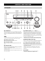
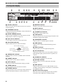
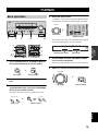
1 STANDBY/ON
Turns on this unit or sets it to the standby mode. When
you turn on this unit, you will hear a click and there will
be a 4 to 5-second delay before this unit can reproduce
sound.
In standby mode, this unit consumes a small amount of power in
order to receive infrared-signals from the remote control.
2 Remote control sensor
Receives signals from the remote control.
3 Front panel display
Shows information about the operational status of this
unit.
4 A/B/C/D/E, NEXT *
Selects one of the 5 preset station groups (A to E) when
the unit is in FM/AM tuner mode.
Switches to the top of the service list when the unit is in
DAB tuner mode.
Selects the speaker channel to be adjusted when the unit is
not in tuner mode.
5 PRESET/TUNING l / h, LEVEL –/+ *
Selects preset station number 1 to 8 when the colon (:) is
displayed next to the band indication in the front panel
display when the unit is in FM/AM tuner mode. Selects
the tuning frequency when the colon (:) is not displayed.
Browses through the list of stored or preset services when
this unit is in DAB tuner mode.
Adjusts the level of the speaker channel selected using
A/B/C/D/E (NEXT) when the unit is not in tuner mode.
6 MEMORY (MAN’L/AUTO FM)
Stores a station in the memory. Hold down this button for
more than 3 seconds to start automatic preset tuning.
7 TUNING MODE (AUTO/MAN’L) (DISPLAY) *
Switches between automatic tuning (AUTO indicator on)
and manual tuning (AUTO indicator off) when this unit is
in FM/AM tuner mode.
Displays various service information of the current
broadcast when this unit is in DAB tuner mode (see
page 46).
8 VOLUME
Controls the output level of all audio channels.
This does not affect the OUT (REC) level.
CONTROLS AND FUNCTIONS
Front panel
AUTO/MAN'L DISPLAYMAN'L/AUTO FMLEVEL
NEXT
EFFECT
MEMORY
FM/AMPRESET/TUNING
DABSEARCH MODE
A/B/C/D/E
PROGRAM
l PRESET/TUNING h
TUNING MODE
INPUT MODETONE CONTROLSTRAIGHT
SPEAKERS
PHONES
SILENT CINEMA
STANDBY
/ON
BA
MULTI CH
INPUT
VOLUME
INPUT
VIDEO L AUDIO R
VIDEO AUX
EDIT
DISPLAY
213456
FGHDCA0B E
I
7
8
9
Note

CONTROLS AND FUNCTIONS
5
INTRODUCTION
English
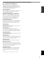
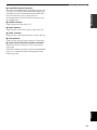
9 PHONES (SILENT CINEMA) jack
Outputs audio signals for private listening with
headphones. When you connect headphones, no signals
are output to the OUTPUT jacks or to the speakers.
All Dolby Digital and DTS audio signals are mixed down
to the left and right headphone channels.
0 SPEAKERS A/B
Turns on or off the set of front speakers connected to the A
and/or B terminals on the rear panel each time the
corresponding button is pressed.
A PRESET/TUNING (EDIT)* SERCH MODE
Switches the function of PRESET/TUNING l / h
(LEVEL –/+) between selecting preset station numbers
and tuning when this unit is in FM/AM tuner mode.
Switches between the AUTO and PRESET tuning
methods when this unit is in DAB tuner mode.
B STRAIGHT (EFFECT)
Switches the sound fields off or on. When STRAIGHT is
selected, input signals (2-channel or multi-channel) are
output directly from their respective speakers without
effect processing.
C FM/AM, DAB
Switches the reception band between FM, AM, or DAB
when the unit is in tuner mode.
D PROGRAM l / h
Use to select sound field programs (see page 26).
Use to adjust the bass/treble balance for the front left and
right speakers (in conjunction with TONE CONTROL).
E TONE CONTROL
Use to adjust the bass/treble balance for the front left and
right speakers (see page 26).
F INPUT MODE
Sets the priority (AUTO, DTS, ANALOG) for the type of
signals received when one component is connected to two
or more of this unit’s input jacks (see page 31).
G INPUT selector
Selects the input source you want to listen to or watch.
H MULTI CH INPUT
Selects the source connected to the MULTI CH INPUT
jacks. When selected, the MULTI CH INPUT source takes
priority over the source selected with INPUT (or the input
selector buttons on the remote control).
I VIDEO AUX jacks
Input audio and video signals from a portable external
source such as a game console. To reproduce source
signals from these jacks, select V-AUX as the input
source.
* Used when the unit is in DAB reception mode (see page 42).

CONTROLS AND FUNCTIONS
6
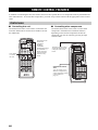
This section describes the function of each control on the
remote control used to control this unit. To operate other
components, see “REMOTE CONTROL FEATURES” on
page 66.
1 Infrared window
Outputs infrared control signals. Aim this window at the
component you want to operate.
2 Input selector buttons
Select the input source and change the control function.
3 Radio Data System tuning buttons
FREQ/TEXT
Press this button when the unit is receiving a Radio Data
System station to cycle the display between the PS mode,
PTY mode, RT mode, CT mode (if the station offers those
Radio Data System data services) and/or the frequency
display (see page 39).
PTY SEEK MODE
Press this button to set the unit to the PTY SEEK mode
(see page 40).
PTY SEEK START
Press this button to begin searching for a station after the
desired program type has been selected in the PTY SEEK
mode (see page 40).
EON
Press this button to select a radio program type (NEWS,
INFO, AFFAIRS, SPORT) to tune in automatically (see
page 41).
4 Sound field program/numeric buttons
Use to select sound field programs.
Use numbers 1 through 8 to select preset stations when the
unit is in tuner mode.
Use SELECT to playback 2-channel sources in surround
(see page 29).
Use EXTD SUR. to switch between 5.1 or 6.1-channel
playback of multi-channel sources (see page 28).
Use DIRECT ST. to playback 2-channel sources in high
fidelity sound (see page 30).
5 SPEAKERS A/B
Use to turn on or off the set of front speakers connected to
the A and/or B terminals on the rear panel each time the
corresponding button is pressed.
6 LEVEL (BAND)
Selects the speaker channel to be adjusted and sets the
level.
Switches the reception band between FM, AM, and DAB
when the unit is in tuner mode.
7 Cursor buttons u / d / j / i / ENTER
Use to select and adjust sound field program parameters or
SET MENU items.
Press i to select a preset station group (A to E) when the
unit is in tuner mode.
Press u / d to select a preset station number (1 to 8)
when the unit is in tuner mode.
Remote control
CODE SET
STANDBY
SYSTEM
POWER
CD
MD/CD-R
TUNER
V-AUXDVD
AMP
POWER POWER
REC
AUDIO
MUTE
MENUTITLE
VOLUME
DISC SKIP
FREQ/TEXT EON
START
SET MENU
LEVEL
A/B/C/D/E
MODE PTY SEEK
PRESET/CH
STRAIGHT
MOVIEENTERTAINMUSIC
STEREO
4321
8
10
7
09
65
ENT.
DIRECT ST.EXTD SUR.STANDARD
SELECT
NIGHT
B
SPEAKERS
A
DISPLAYRETURN
TV MUTE TV INPUT
TV VOL TV CH
AVTV
ENTER
VCR
DTV/CBL
MULTI CH IN
SLEEP
A/B/C/D/E
BAND
SRCH MODE
MEMORY
9
0
A
B
C
D
E
F
G
I
J
1
2
4
5
7
6
8
H
3

CONTROLS AND FUNCTIONS
7
INTRODUCTION
English
8 RETURN (MEMORY)
Returns to the previous menu level when adjusting the
SET MENU parameters.
9 STANDBY
Sets this unit in the standby mode.
0 SYSTEM POWER
Turns on the power of this unit.
A SLEEP
Sets the sleep timer (see page 55).
B MULTI CH IN
Selects multi-channel input when using an external
decoder (etc.).
C CODE SET
Use to set up remote control codes (see page 67).
D AMP
Selects the AMP mode. You must select the AMP mode to
control the main unit.
E VOLUME +/–
Increases or decreases the volume level.
F MUTE
Mutes the sound. Press again to restore the audio output to
the previous volume level.
G STRAIGHT
Switches the sound fields off or on. When STRAIGHT is
selected, input signals (2-channel or multi-channel) are
output directly from their respective speakers without
effect processing.
H NIGHT
Turns on or off the night listening modes (see page 30).
I SET MENU (MENU)
Activates the SET MENU function (see page 57).
J DISPLAY
Displays various service information of the current
broadcast when this unit is in DAB tuner mode (see
page 46).
The remote control transmits a directional infrared beam.
Be sure to aim the remote control directly at the remote
control sensor on the main unit during operation.
■ Handling the remote control
• Do not spill water or other liquids on the remote
control.
• Do not drop the remote control.
• Do not leave or store the remote control in the
following types of conditions:
– places of high humidity, such as near a bath
– high temperature, such as near a heater or stove
– extremely low temperatures
– dusty places
Using the remote control
AUTO/MAN'L DISPLAYMAN'L/AUTO FMLEVEL
NEXT
EFFECT
MEMORY
FM/AMPRESET/TUNING
A/B/C/D/E
PROGRAM
l PRESET/TUNING h
TUNING MODE
INPUT MODETONE CONTROLSTRAIGHT
SPEAKERS
PHONES
SILENT CINEMA
STANDBY
/ON
BA
MULTI CH
INPUT
VOLUME
INPUT
VIDEO L AUDIO R
VIDEO AUX
MAIN ZONE 2
EDIT
SEARCH MODE DAB
DISPLAY
30 30
CODE SET
STANDBY
SYSTEM
POWER
CD
MD/CD-R
TUNER
V-AUXDVD
AMP
POWER POWER
REC
AUDIO
MUTE
MENUTITLE
VOLUME
DISC SKIP
FREQ/TEXT EON
START
SET MENU
SRCH MODE
LEVEL
BAND
MEMORY
A/B/C/D/EA/B/C/D/E
MODE PTY SEEK
PRESET/CH
STRAIGHT
MOVIEENTERTAINMUSIC
STEREO
4321
8
10
7
09
65
ENT.
DIRECT ST.EXTD SUR.STANDARD
SELECT
NIGHT
B
SPEAKERS
A
DISPLAYRETURN
TV MUTE TV INPUT
TV VOL TV CH
AVTV
ENTER
VCR
DTV/CBL
MULTI CH IN
SLEEP
Approximately 6 m

CONTROLS AND FUNCTIONS
8
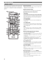
1 Decoder indicators
When any of this unit’s decoders function, the respective
indicator lights up.
2 STANDARD indicator
Lights up when Surround Standard or Surround Enhanced
is selected (see page 29).
3 SILENT CINEMA indicator
Lights up when headphones are connected and a sound
field program is selected (see page 26).
4 Input source indicators
A cursor lights to show the current input source.
5 Sound field indicators
Light to indicate the active DSP sound fields.
6 CINEMA DSP indicator
Lights up when you select a CINEMA DSP sound field
program.
7 PRESET indicator
Lights up when a preset station is selected.
8 AUTO indicator
Lights up to indicate that automatic tuning is possible.
9 TUNED indicator
Lights up when this unit is tuned into a station.
0 STEREO indicator
Lights up when this unit is receiving a strong signal for an
FM stereo broadcast while the AUTO indicator is lit.
A MEMORY indicator
Flashes to show that a station can be stored.
B MUTE indicator
Flashes while the MUTE function is on.
C VOLUME level indicator
Indicates the current volume level.
D PCM indicator
Lights up when this unit is reproducing PCM (Pulse Code
Modulation) digital audio signals.
E SECONDARY indicator
Lights up when a secondary signal is selected.
F DAB indicator
Lights up when Digital Audio Broadcasting mode is
selected.
G NIGHT indicator
Lights up when you select night listening mode.
H SP A B indicators
Light up according to the set of front speakers selected.
Both indicators light up when both sets of speakers are
selected.
I Headphones indicator
Lights up when headphones are connected.
J HiFi DSP indicator
Lights up when you select a HiFi DSP sound field
program.
K DRC indicator
Lights up when this unit is set to DRC MODE: AUTO:
and DRC (Dynamic Range Control) data is transmitted in
the DAB tuner mode.
L Multi-information display
Shows the current sound field program name and other
information when adjusting or changing settings.
Front panel display
CDTUNER
MD/CD-R
DVD
DTV/CBL
V-AUX
VIRTUAL
VCR
96
24
q
PL
q
EX
q
PL
MATRIX DISCRETE
SILENT CINEMA
NIGHT
DAB
STANDARD
AUTO
PS PTY RT CT EON
PTY HOLD
TUNED STEREO MUTE
VOLUME
MEMORY
SLEEP
PCM
q
PL x
A B
SP
mS
dB
ft
dB
96/24
HiFi DSP
LFE
DUAL
LCR
SL SB SR
q
DIGITAL
t
SECONDARY
DRC
PRESET
1345689ABC0
GH
M
IK
LQPROFED
2
J
N
7
Presence DSP sound field
Listening position
Left surround
DSP sound field
Right surround
DSP sound field
Surround back DSP sound field

CONTROLS AND FUNCTIONS
9
INTRODUCTION
English
M Radio Data System indicators
The name(s) of the Radio Data System data offered by the
currently received Radio Data System station light(s) up.
EON lights up when an Radio Data System station that
offers the EON data service is being received.
PTY HOLD lights up while searching for stations in the
PTY SEEK mode.
N SLEEP indicator
Lights up while the sleep timer is on.
O 96/24 indicator
Lights up when a DTS 96/24 signal is input to this unit.
P DUAL indicator
Lights up when a dual monaural signal is input to this unit.
Q LFE indicator
Lights up when the input signal contains the LFE signal.
R Input channel indicators/speaker indicators
Indicate the channel components of the current digital
input signal.
Indicate the number of speakers connected in SPEAKERS
(page 23), or indicate the channel being adjusted in SP
LEVEL (page 60).

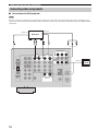
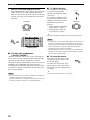
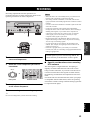
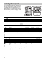
CONTROLS AND FUNCTIONS
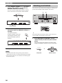
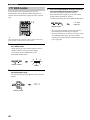
10
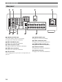
1 DIGITAL OUTPUT jack
Used when making a MD or CD recording.
See page 19 for connection information.
2 MULTI CH INPUT jacks
See page 17 for connection information.
3 Video component jacks
See pages 16 and 18 for connection information.
4 DAB antenna terminal
See page 21 for connection information.
5 AC OUTLETS
Use to supply power to your other A/V components (see
page 21).
6 DIGITAL INPUT jacks
See pages 16, 18 and 19 for details.
7 Audio component jacks
See page 19 for connection information.
8 SUBWOOFER OUTPUT jack
See page 13 for connection information.
9 Antenna terminals
See page 20 for connection information.
0 Speaker terminals
See page 13 for connection information.
Rear panel
SPEAKERS
FRONT
CENTER
SURROUND
SURROUND
BACK
R
R
L
L
CENTER
SUB
WOOFER
MONITOR OUT
MULTI CH INPUT
OUTPUT
AUDIO
AUDIO
VIDEO
S VIDEO
DVD
DTV
/CBL
VIDEO
R
L
R
L
IN
(
PLAY
)
OUT
(
REC
)
MD
/CD-R
CD
OUT
VCR
VIDEO
IN
FRONT
SURROUND
TUNER
AM
ANT
GND
COMPONENT VIDEO
P
R
DVD
MONITOR
OUT
DTV
/CBL
P
B
Y
+
–
+
–
A
B
FM
ANT
SUB
WOOFER
S VIDEO
R
L
AC OUTLETS
SWITCHED
100W MAX. TOTAL
75W UNBAL.
DIGITAL
INPUT
DVD
CD
COAXIAL
DTV/CBL
MD/CD-R
MD/CD-R
DIGITAL
OUTPUT
OPTICAL
DAB
+
–
+
–
+
–
+
–
+
–
+
–
12 3 5
6
4
78 9
0

SPEAKER SETUP
11
PREPARATION
English
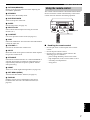
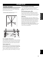
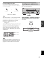
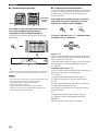
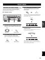
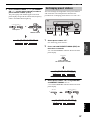
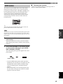
The speaker layout below shows the standard ITU-R
*
speaker setting. You can use it to enjoy CINEMA DSP
and multi-channel audio sources.
*
ITU-R is the radio communication sector of the ITU
(International Telecommunication Union)
.
Front speakers (FR and FL)
The front speakers are used for the main source sound plus
effect sounds. Place these speakers an equal distance from
the ideal listening position. The distance of each speaker
from each side of the video monitor should be the same.
Center speaker (C)
The center speaker is used for the center channel sounds
(dialog, vocals, etc.). If for some reason it is not practical
to use a center speaker, you can do without it. Best results,
however, are obtained with the full system. Place the
speaker centrally between the front speakers and as close
to the monitor as possible, such as directly over or under
it.
Surround speakers (SR and SL)
The surround speakers are used for effect and surround
sounds. Place these speakers behind your listening
position, facing slightly inwards, about 1.8 m (6 ft) above
the floor.
Surround back speaker (SB)
The surround back speaker supplements the surround
speakers and provides for more realistic front-to-back
transitions. Place this speaker directly behind the listening
position and at the same height as the surround speakers.
Subwoofer
The use of a subwoofer, such as the YAMAHA Active
Servo Processing Subwoofer System, is effective not only
for reinforcing bass frequencies from any or all channels,
but also for high fidelity reproduction of the LFE (low-
frequency effect) channel included in Dolby Digital and
DTS software. The position of the subwoofer is not so
critical, because low bass sounds are not highly
directional. But it is better to place the subwoofer near the
front speakers. Turn it slightly toward the center of the
room to reduce wall reflections.
SPEAKER SETUP
Speaker placement
60˚
30˚
SB
FL
FR
C
SL
SR
SR
80˚
SL
1.8 m

12
SPEAKER SETUP
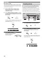
Be sure to connect the left channel (L), right channel (R),
“+” (red) and “–” (black) properly. If the connections are
faulty, no sound will be heard from the speakers, and if the
polarity of the speaker connections is incorrect, the sound
will be unnatural and lack bass.
• If you use 4 or 6 ohm speakers, be sure to set
this unit’s speaker impedance setting to
4 ohms before using (see page 14).
• Before connecting the speakers, make sure that the
power of this unit is off.
• Do not let the bare speaker wires touch each other or
do not let them touch any metal part of this unit. This
could damage this unit and/or speakers.
• Use magnetically shielded speakers. If this type of
speakers still creates the interference with the monitor,
place the speakers away from the monitor.
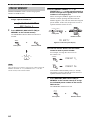
A speaker cord is actually a pair of insulated cables
running side by side. One cable is colored or shaped
differently, perhaps with a stripe, groove or ridges.
Connect the striped (grooved, etc.) cable to the “+” (red)
terminals on this unit and your speaker. Connect the plain
cable to the “–” (black) terminals.
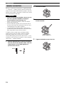
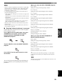
1 Remove approximately 10 mm of insulation
from the end of each speaker cable. Twist the
exposed wires of the cable together to
prevent short circuits.
2 Unscrew the knob.
3 Insert one bare wire into the hole in the side
of each terminal.
4 Tighten the knob to secure the wire.
Speaker connections
CAUTION
10 mm
Red: positive (+)
Black: negative (–)

13
SPEAKER SETUP
PREPARATION
English
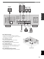
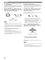
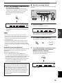
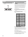
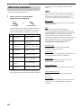
■ FRONT terminals
Connect one or two speaker systems (2, 3) to these
terminals. If you use only one speaker system, connect it
to the FRONT A or B terminals.
■ CENTER terminals
Connect a center speaker (4) to these terminals.
■ SURROUND terminals
Connect surround speakers (6, 7) to these terminals.
■ SUBWOOFER jack
Connect a subwoofer with built-in amplifier (1), such as
the YAMAHA Active Servo Processing Subwoofer
System, to this jack.
■ SURROUND BACK terminals
Connect a surround back speaker (5) to these terminals.
SPEAKERS
FRONT
CENTER
SURROUND
SURROUND
BACK
R
R
L
L
OUTPUT
+
–
+
–
–
+
––
+++
+
+
–
–
–
A
B
SUB
WOOFER
AC OUTLETS
SWITCHED
100W MAX. TOTAL
DAB
DAB
DVD
DTV/CBL
MD/CD-R
MD/CD-R
DIGITAL
OUTPUT
OPTICAL
2 3 6 71
54
Subwoofer
system
Center
speaker
Front speakers (A)
Surround back
speaker
LeftRight
LeftRight
Surround speakers
Front
speakers
(B)
1
2
3
4
5
7
6
Speaker layout

14
SPEAKER SETUP
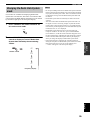
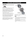
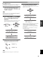
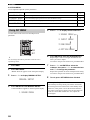
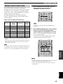
If you are using 4 or 6 ohm speakers, set the impedance to
4 or 6 ohms as follows before turning on the power.
Be sure this unit is in the standby mode.
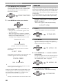
1 While this unit is in standby mode, hold
down STRAIGHT (EFFECT) and press
STANDBY/ON.
This unit turns on, and the ADVANCED SETUP
menu appears in the front panel display.
2 Rotate PROGRAM to move through the menu
and select “SP IMP.”.
3 Press STRAIGHT (EFFECT) repeatedly to
select “4Ω MIN”.
4 Press STANDBY/ON to confirm your
selection.
This unit is switched back to standby mode. The setting
you made is reflected the next time this unit’s power is
turned on.
Speaker impedance setting
CAUTION
AUTO/MAN'L DISPLAYMAN'L/AUTO FMLEVEL
NEXT
EFFECT
MEMORY
FM/AMPRESET/TUNING
A/B/C/D/E
PROGRAM
l PRESET/TUNING h
TUNING MODE
INPUT MODETONE CONTROLSTRAIGHT
SPEAKERS
PHONES
SILENT CINEMA
BA
MULTI CH
INPUT
VOLUME
INPUT
VIDEO L AUDIO R
VIDEO AUX
EDIT
SEARCH MODE DAB
DISPLAY
STANDBY
/ON
1,3 2
1,4
STANDBY
/ON
EFFECT
STRAIGHT
While holding
down, press
PROGRAM
EFFECT
STRAIGHT
STANDBY
/ON

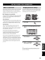
CONNECTING AUDIO AND VIDEO COMPONENTS
15
PREPARATION
English
Do not connect this unit or other components to the main
power until all connections between components are
complete.
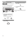
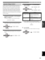
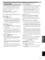
■ Cable indications
■ Analog jacks
You can input analog signals from audio components by
connecting audio pin cable to the analog jacks on this unit.
Connect red plugs to the right jacks and white plugs to the
left jacks.
■ Digital jacks
This unit has digital jacks for direct transmission of digital
signals through either coaxial or fiber optic cables. You
can use the digital jacks to input PCM, Dolby Digital and
DTS bitstreams. When you connect components to both
the COAXIAL and OPTICAL jacks, priority is given to
the input signals from the COAXIAL jack. All digital
input jacks are compatible with 96-kHz sampling digital
signals.
This unit handles digital and analog signals independently. Thus
audio signals input to the analog jacks are only output to the
analog OUT (REC) jacks.
Dust protection cap
Pull out the cap from the optical jack before you connect
the fiber optic cable. Do not discard the cap. When you are
not using the optical jack, be sure to put the cap back in
place. This cap protects the jack from dust.
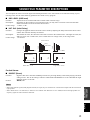
■ Video jacks
This unit has three types of video jacks. Connection
depends on the availability of input jacks on your monitor.
VIDEO jacks
For conventional composite video signals.
S VIDEO jacks
For S-video signals, separated into luminance (Y) and
color (C) video signals to achieve high-quality color
reproduction.
COMPONENT VIDEO jacks
For component signals, separated into luminance (Y) and
color difference (P
B, PR) to provide the best quality in
picture reproduction.
CONNECTING AUDIO AND VIDEO COMPONENTS
Before connecting components
Note
CAUTION
S
V
O
L
R
C
Y
P
B
PR
left analog cables
right analog cables
optical cables
coaxial cables
video cables
For analog signals
For digital signals
For video signals
S-video cables
component video cables
VIDEO
S VIDEO
COMPONENT VIDEO
P
R
P
B
Y
S VIDEO
VIDEO
COMPONENT
VIDEO
Signal flow inside this unit
Output
(MONITOR OUT)
Input

16
CONNECTING AUDIO AND VIDEO COMPONENTS
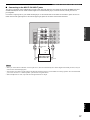
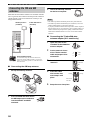
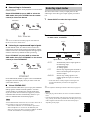
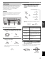
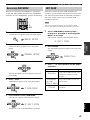
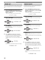
■ Connections for DVD playback
Be sure to connect your video source components in the same way you connect your video monitor to this unit. For example, if you
connect your video monitor to this unit using a VIDEO connection, connect your video source components to this unit using the VIDEO
connections.
Connecting video components
Note
MONITOR OUT
AUDIO
VIDEO
DVD
VIDEO
R
L
VIDEO
COMPONENT VIDEO
PR
DVD
MONITOR
OUT
PB
Y
S VIDEO
S VIDEO
DVD
DTV/CBL
MD/CD-R
DIGITAL
OUTPUT
OPTICAL
LR
O
S
P
R PB Y
V
DVD player
Video
monitor
Optical out
Video out
Audio out
Video in

17
CONNECTING AUDIO AND VIDEO COMPONENTS
PREPARATION
English
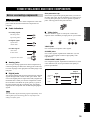
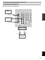
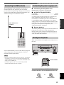
■ Connecting to the MULTI CH INPUT jacks
This unit is equipped with 6 additional input jacks (left and right FRONT, CENTER, left and right SURROUND and
SUBWOOFER) for discrete multi-channel input from a multi-format player, external decoder, sound processor or
pre-amplifier.
Connect the output jacks on your multi-format player or external decoder to the MULTI CH INPUT jacks. Be sure to
match the left and right outputs to the left and right input jacks for the front and surround channels.
• When you select MULTI CH INPUT as the input source, this unit automatically turns off the digital sound field processor, and you
cannot select sound field programs.
• This unit does not redirect signals input to the MULTI CH INPUT jacks to accommodate for missing speakers. We recommend that
you connect at least a 5.1-channel speaker system before using this feature.
• When headphones are used, only front left and right channels are output.
Notes
CENTER
SUB
WOOFER
MULTI CH INPUT
FRONT
SURROUND
R
L
MD/CD-R
DIGITAL
OUTPUT
OPTICAL
LRLR
Multi-format player/
External decoder
Front
out
Surround
out
Subwoofer
out
Center
out

18
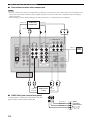
CONNECTING AUDIO AND VIDEO COMPONENTS
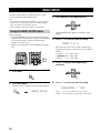
■ Connections for other video components
• Be sure to connect your video source components in the same way you connect your video monitor to this unit. For example, if you
connect your video monitor to this unit using a VIDEO connection, connect your video source components to this unit using the
VIDEO connection.
• When recording, you must make the same type of video connections (i.e., S-video) between each component.
■ VIDEO AUX jacks (on the front panel)
Use these jacks to connect any video source, such as a
game console or video camera, to this unit.
Notes
MONITOR OUT
AUDIO
VIDEO
DTV/
CBL
VIDEO
R
L
OUT
VCR
VIDEO
IN
COMPONENT VIDEO
PR
MONITOR
OUT
DTV/
CBL
PB
Y
S VIDEO
S VIDEO
DTV/CBL
MD/CD-R
DIGITAL
OUTPUT
OPTICAL
O
LR
LR LR
V
S
P
R PB Y
S
V
S
V
Cable TV or
satellite tuner
DVD recorder
or VCR
Audio out
Video out
Optical out
Audio out
Video out
Video inAudio in
Video in
Video
monitor
VIDEO L AUDIO R
VIDEO AUX
V
L
R
Game
console or
video camera
Video out
Audio out L
Audio out R
Sidan laddas ...
Sidan laddas ...
Sidan laddas ...
Sidan laddas ...
Sidan laddas ...
Sidan laddas ...
Sidan laddas ...
Sidan laddas ...
Sidan laddas ...
Sidan laddas ...
Sidan laddas ...
Sidan laddas ...
Sidan laddas ...
Sidan laddas ...
Sidan laddas ...
Sidan laddas ...
Sidan laddas ...
Sidan laddas ...
Sidan laddas ...
Sidan laddas ...
Sidan laddas ...
Sidan laddas ...
Sidan laddas ...
Sidan laddas ...
Sidan laddas ...
Sidan laddas ...
Sidan laddas ...
Sidan laddas ...
Sidan laddas ...
Sidan laddas ...
Sidan laddas ...
Sidan laddas ...
Sidan laddas ...
Sidan laddas ...
Sidan laddas ...
Sidan laddas ...
Sidan laddas ...
Sidan laddas ...
Sidan laddas ...
Sidan laddas ...
Sidan laddas ...
Sidan laddas ...
Sidan laddas ...
Sidan laddas ...
Sidan laddas ...
Sidan laddas ...
Sidan laddas ...
Sidan laddas ...
Sidan laddas ...
Sidan laddas ...
Sidan laddas ...
Sidan laddas ...
Sidan laddas ...
Sidan laddas ...
Sidan laddas ...
Sidan laddas ...
Sidan laddas ...
Sidan laddas ...
Sidan laddas ...
Sidan laddas ...
Sidan laddas ...
Sidan laddas ...
Sidan laddas ...
Sidan laddas ...
Sidan laddas ...
Sidan laddas ...
Sidan laddas ...
Sidan laddas ...
-
 1
1
-
 2
2
-
 3
3
-
 4
4
-
 5
5
-
 6
6
-
 7
7
-
 8
8
-
 9
9
-
 10
10
-
 11
11
-
 12
12
-
 13
13
-
 14
14
-
 15
15
-
 16
16
-
 17
17
-
 18
18
-
 19
19
-
 20
20
-
 21
21
-
 22
22
-
 23
23
-
 24
24
-
 25
25
-
 26
26
-
 27
27
-
 28
28
-
 29
29
-
 30
30
-
 31
31
-
 32
32
-
 33
33
-
 34
34
-
 35
35
-
 36
36
-
 37
37
-
 38
38
-
 39
39
-
 40
40
-
 41
41
-
 42
42
-
 43
43
-
 44
44
-
 45
45
-
 46
46
-
 47
47
-
 48
48
-
 49
49
-
 50
50
-
 51
51
-
 52
52
-
 53
53
-
 54
54
-
 55
55
-
 56
56
-
 57
57
-
 58
58
-
 59
59
-
 60
60
-
 61
61
-
 62
62
-
 63
63
-
 64
64
-
 65
65
-
 66
66
-
 67
67
-
 68
68
-
 69
69
-
 70
70
-
 71
71
-
 72
72
-
 73
73
-
 74
74
-
 75
75
-
 76
76
-
 77
77
-
 78
78
-
 79
79
-
 80
80
-
 81
81
-
 82
82
-
 83
83
-
 84
84
-
 85
85
-
 86
86
-
 87
87
-
 88
88


Yamaha RX-V100D Bruksanvisning
- Kategori
- AV-mottagare
- Typ
- Bruksanvisning
på andra språk
- italiano: Yamaha RX-V100D Manuale del proprietario
- Deutsch: Yamaha RX-V100D Bedienungsanleitung
- français: Yamaha RX-V100D Le manuel du propriétaire
- Türkçe: Yamaha RX-V100D El kitabı
- English: Yamaha RX-V100D Owner's manual
- dansk: Yamaha RX-V100D Brugervejledning
- Nederlands: Yamaha RX-V100D de handleiding
- română: Yamaha RX-V100D Manualul proprietarului
Relaterade papper
-
Yamaha RX-V559 Bruksanvisning
-
-
Yamaha RX-V459 Bruksanvisning
-
-
Yamaha T-D500 Bruksanvisning
-
Yamaha RX-A1080 Bruksanvisning
-
-
Yamaha RX-A1070 Bruksanvisning
-
Yamaha RX-A880 Bruksanvisning
-
Yamaha MUSICCAST R-N402DMUSICCAST RN402 Bruksanvisning
Andra dokument
-
Tangent ALIO BAZE MONO CD/DAB+/FM/BT White High Gloss Användarmanual
-
-
Rotel RT-02 Användarmanual
-
Clas Ohlson CD-726DAB Användarmanual
-
Sony XDR-S41D Bruksanvisning
-
-
P. Lindberg LXRM03 Bruksanvisning
-
Matsui M1DAB11E Användarmanual
-
-