
COMPLETE HEATING SOLUTIONS
KICKSPACE
®
500, 600
600-12V, 800, 80S & 80D
INSTALLATION & OPERATING MANUAL
INSTALLATIONS- OCH ANVÄNDARHANDBOK
PLEASE LEAVE THIS MANUAL WITH THE END USER
LÄMNA DEN HÄR HANDBOKEN TILL SLUTANVÄNDAREN
EN
SE

1.0 Safety Information
For MYSON KICKSPACE
®
500, 600, 600-12V,
800, 80S & 80D, a fused (3A) electrical spur with
a switch having 3mm separation on all poles must
be provided in an easily accessible position
adjacent to the unit.
For the KICKSPACE
®
600-12V, a fused electrical
spur having 3mm separation on all poles must be
provided in an easily accessible position adjacent
to the transformer. Both the fused spur and the
transformer must not be positioned in a
bathroom or other similar high humidity area.
If the supply cord to the KICKSPACE
®
500, 600,
600-12V, 800, 80S & 80D is damaged, it must be
replaced by the manufacturer, its service agent or
similar qualified persons in order to avoid a
hazard.
This appliance can be used by children aged from
8 years and above and persons with reduced
physical or mental capabilities or lack of
experience and knowledge if they have been
given supervision or instruction concerning the
use of the appliance in a safe way and understand
the hazards involved.
Children shall not play with the appliance.
Cleaning and user maintenance shall not be made
by children unless they are older than 8 years and
supervised.
Keep the appliance and its cord out of reach of
children aged less than 8 years.
Children of less than 3 years should be kept
away from the unit unless continuously
supervised.
Children aged from 3 years and less than 8 years
shall only switch on / off the appliance provided
that it has been placed or installed in its normal
operating position and they have been given
supervision or instruction concerning use of the
appliance in a safe way and understand the
hazards involved.
Children aged from 3 years and less than 8 years
shall not plug in, clean the appliance or perform
user maintenance.
WARNING: KICKSPACE
®
500, 600, 800, 80S & 80D models must be earthed.
1.0 Safety Information 02
2.0 Installation 03
3.0 Water Connection 03
4.0 Electrical Connection 04
5.0 Controls 04
6.0 Troubleshooting 04
7.0 Appendix 08
Contents
The KICKSPACE
®
500, 600 600-12V, 800, 80S & 80D MUST NOT be installed in a bathroom or
other similar high humidity area.
02
KICKSPACE
®
500, 600, 600-12V, 800, 80S & 80D
KICKSPACE
®
500, 600, 600-12V, 800, 80S & 80D
INSTALLATION & OPERATING MANUAL
01.07.2018
EN

03
KICKSPACE
®
500, 600, 600-12V, 800, 80S & 80D
2.0 Installation
l Before proceeding with the installation, the heating system
design must be considered and the unit correctly sized to
meet the heat loss requirements of the room.
l Before proceeding with the installation, unpack the carton
contents and check against the checklist below:
1. KICKSPACE
®
unit.
2. Flexible hoses including isolating valves (1 pair).
3. Instruction manual.
4. Grille - supplied seperate.
5. Screw fixing kit (with grille) - supplied seperate.
6. Transformer (12V model only).
7. Connector (12V model only).
l This MYSON KICKSPACE
®
fan convector is designed for
installation in the cavity beneath kitchen cupboards on the
vacant floor space, or other similar locations.
l For KICKSPACE
®
500, 600, 600-12V & 800 a minimum of
25mm clear headroom is required above the top of the
KICKSPACE
®
when fitted.
l The unit should be mounted on a clean and level floor area
under the cupboard base.
l KICKSPACE
®
80S & 80D models can only be installed if there
is a minimum height of 80mm from the top of the floor
covering to the underside of the kitchen unit (see Fig. 1).
l KICKSPACE
®
500, 600, 600-12V & 500 floor mounting (see
Fig. 2a) - The KICKSPACE
®
is normally fitted directly onto the
floor and the base of the unit is fitted with four mounting feet.
l KICKSPACE
®
500, 600, 600-12V & 500 plinth mounting
(see Fig. 2b) -
• As an alternative to floor mounting the unit may be fitted
into the plinth.
• A suitable support must be securely fitted to the floor.
• The top of the support must be level with the lower edge of
the cut-out when fitted.
l KICKSPACE
®
80S & 80D floor mountings (see Fig. 2c) - Applies
to 80S & 80D units in 80mm plinth height kitchen unit.
l Decide the position of the KICKSPACE
®
, mark out and cut the
plinth to the dimensions using table on page 9.
l Position the KICKSPACE
®
under the cupboard in the required
location, with the front edge just behind the line of the plinth.
l Replace the plinth and bring the KICKSPACE
®
forward into
the opening so the front edge projects approximately 10mm
through the plinth.
l Align the grille and secure it to the unit with two screws
supplied (use the shorter screws). (See Fig. 3).
l Secure the unit/grille to the plinth with two screws supplied
(use the longer screws). (See Fig. 3).
l Complete the electrical installation, switch on and test the
KICKSPACE
®
(see Fig. 3).
l When installed in a kitchen consideration should be given to
storage of perishable goods in the cupboard above.
3.0 Water Connection
l The KICKSPACE
®
should only be used on closed circulation,
two pipe, pump assisted central heating systems.
l For optimum fan convector heating performance the system
must be capable of providing sufficient hot water through the
heat exchanger. This means that:
1. The minimum pipe size from boiler to fan convector must
be at least 15mm. Microbore pipe MUST NOT be used.
2. Where the unit is fitted on to a system with other emitters
a separate circuit for the fan convector should be
considered to provide adequate water flow.
3. The system water temperature on the return of the
KICKSPACE
®
must be above 30°C for the fan to switch on.
4. This unit is NOT suitable for one-pipe systems.
5. Optimum performance will require effective balancing of
the whole system.
6. This unit must not be used to replace a radiator in an
existing system unless an adequate flow of water can be
guaranteed.
l Connect valve ends of the flexible pipes to the KICKSPACE
®
.
Note: The direction of the arrows on the valves are not
significant in this application (see Fig. 4).
l Open valves fully, check pipe connections for leaks and vent
the heat exchanger. A vent screw is provided to vent the heat
exchanger.
Pipework must be positioned correctly to ensure
flexible hoses are not kinked when installed
(see Figs. 5a & 5b). Only use the hose sets
supplied with this unit. Do not use old or
alternative hose sets.
KICKSPACE
®
500, 600, 600-12V, 800, 80S & 80D
INSTALLATION & OPERATING MANUAL
01.07.2018
EN

04
4.0 Electrical Connection
l The electrical installation must be done by a qualified
electrician.
l MYSON KICKSPACE
®
comes equipped with a 2 metre
0.75mm
2
earthed power cable.
l The attached room thermostat also has a built-in main power
switch. For easy installation, use the provided wall adapter. The
adapter is used both for the room thermostat and the MYSON
KICKSPACE
®
unit.
l The room thermostat has a tolerance of max 10A. See Fig. 6
and connection diagram (Figs. 7a and 7b).
l If the power cable to the room thermostat doesn’t come
straight out of wall and into the thermostat housing, please
attach the provided pull relief on the inside of the room
thermostat.
WARNING: MYSON KICKSPACE
®
500, 600, 800, 80S & 80D - the unit must be earthed.
Do not energise the electrical supply until the remaining stages of the installation have been completed.
5.0 Controls
This unit is controlled by the switches on the front of the unit
(see Fig. 3).
Ensure the electricity supply is switched on.
Heating Mode
• Set the heating/fan only switch to heating
• Set fan speed control to position I
• The unit will now run on low fan speed.
The system water temperature on the return of the KICKSPACE
®
must be above 30°C for the fan to switch on*
*Eg. When the mean water temperature is greater than 30°C the
fan will switch on, then when the water temperature drops below
30°C the fan will switch off.
Performance will depend on the water temperature at the coil and
the flow though the coil.
The fan speed can be set to boost by switching the fan speed
switch to II.
A low speed setting is recommended for normal operation with
the higher speeds for boost heating when required.
Off Position
Set the fan speed selector switch to the off (O) position.
Fan Only Mode
If required, the KICKSPACE
®
can be used in summer for air
circulation without heat.
• Set the heating/fan only switch to fan only
• Adjust fan speed to required setting.
KICKSPACE
®
500, 600, 600-12V, 800, 80S & 80D
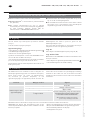
6.0 Troubleshooting
Fan not working in
heating mode
Possible Causes
Unit switched off
Room thermostat not calling for heat
Unit isolating valves shut
Water temperature of
KICKSPACE
®
below 30°C
Problem Remedy
Turn on
Turn up room thermostat
Open valves
Ensure boiler, pump and other central
heating equipment is working correctly,
if not contact your installer
Note: Operation of fan can be checked by
switching to fan only setting
Once installed this fan convector becomes an integral part of a
complete heating system that includes boiler, pump, other
emitters such as radiators and fan convectors, and a number of
heating controls, dependent on system complexity. An apparent
problem with this unit may be the result of system controls being
incorrectly set and can be solved easily without calling out your
installer. Before calling your installer, please carry out the checks
listed below.
KICKSPACE
®
500, 600, 600-12V, 800, 80S & 80D
INSTALLATION & OPERATING MANUAL
01.07.2018
EN
KICKSPACE
®
may have poor performance/cycle if a low water
temperature/flow rate is supplied, please refer to your installer as
this could be from the following:
• Unit incorrectly sized for heat loss of room
• Lack of flow to KICKSPACE
®
from heating system
• Pipe sizes/pump sized incorrectly
• System incorrectly balanced
If the fan convector is still faulty after checking the above, call your installer.

05
KICKSPACE
®
500, 600, 600-12V, 800, 80S & 80D
1.0 Säkerhetsinformation
KICKSPACE
®
500, 600, 600-12V, 800, 80S och
80D måste anslutas till ett uttag som är avsäkrat
med lägst 3A.
Transformatorn till KICKSPACE
®
600-12V får inte
placeras i badrummet och andra utrymmen med
hög luftfuktighet.
Om strömsladden för KICKSPACE
®
500, 600, 600-
12V, 800, 80S eller 80D är skadad måste den av
säkerhetsskäl bytas ut av tillverkaren, ett
serviceombud eller någon annan behörig person.
Den här enheten får användas av barn som är 8 år
och äldre samt personer med nedsatt fysisk eller
mental förmåga eller brist på erfarenhet och
kunskap, om det sker under uppsikt eller om de
instrueras om säker användning av enheten och
förstår de faror som är inblandade.
Barn ska inte leka med enheten. Rengöring och
användarunderhåll får inte utföras av barn
förutom om de är över 8 år och det sker under
uppsikt.
Håll enheten och tillhörande sladd utom räckhåll
för barn under 8 år.
Barn under 3 år ska hållas på avstånd från
enheten förutom om de är under ständig
uppsikt.
Barn i åldrarna 3–8 år får endast slå på/av
enheten om den är placerad eller installerad i
normalt körningsläge och om det sker under
uppsikt eller om de instrueras om säker
användning av enheten och förstår de faror som
är inblandade.
Barn i åldrarna 3–8 år får inte ansluta eller
rengöra enheten eller utföra användarunderhåll.
VARNING! Modellerna KICKSPACE
®
500, 600, 800, 80S och 80D måste jordas.
1.0 Säkerhetsinformation 05
2.0 Installation 06
3.0 Vattenanslutning 06
4.0 Elektrisk anslutning 07
5.0 Reglering 07
6.0 Felsökning 07
7.0 Bilaga 08
Innehållsförteckning
KICKSPACE
®
500, 600 600-12V, 800, 80S och 80D FÅR INTE installeras i badrum eller andra
utrymmen med hög fuktighet.
SE
KICKSPACE
®
500, 600, 600-12V, 800, 80S & 80D INSTALLATIONS- OCH ANVÄNDARHANDBOK
01.07.2018

06
KICKSPACE
®
500, 600, 600-12V, 800, 80S & 80D
2.0 Installation
l Uppvärmningssystemets konstruktion måste ses över och
enheten måste dimensioneras korrekt innan installationen
påbörjas för att kraven för värmeförlust i rummet ska
uppfyllas.
l Packa upp innehållet i kartongen och kontrollera mot
checklistan nedan innan installationen påbörjas:
1. KICKSPACE
®
-enhet.
2. Flexibla slangar inklusive isoleringsventiler (ett par).
3. Bruksanvisning.
4. Galler - tillhandahålls separat.
5. Skruvfixeringssats (med galler) - tillhandahålls separat.
6. Transformator (endast 12V-modellen).
7. Kontakt (endast 12V-modellen).
l Den här MYSON KICKSPACE
®
-fläktkonvektorn är utformad
för installation i hålrummet under köksskåp på det tomma
golvutrymmet, eller annan liknande plats.
l För KICKSPACE
®
500, 600, 600-12V och 800 krävs minst 25
mm fri höjd ovanför toppen av KICKSPACE
®
när den är
monterad.
l Enheten ska monteras på en ren och plan golvyta under
skåpbasen.
l KICKSPACE
®
-modellerna 80S och 80D kan endast installeras
om det finns fri höjd på minst 80 mm från golvskyddet till
undersidan på köksenheten (se fig. 1).
l Golvmontering av KICKSPACE
®
500, 600, 600-12V och 500
(se fig. 2a) - KICKSPACE
®
monteras normalt direkt på golvet
och enhetens bas fästs med fyra monteringsfötter.
l Sockelmontering av KICKSPACE
®
500, 600, 600-12V och 500
(se fig. 2b):
• Enheten kan fästas i sockeln som ett alternativ till
golvmontering.
• Ett lämpligt stöd måste fästas säkert i golvet.
• Toppen på stödet måste vara i nivå med nederkanten på
avstängningsläget när det har monterats.
l Golvmontering av KICKSPACE
®
80S och 80D (se fig. 2c) -
Gäller för enheterna 80S och 80D i köksenheter med 80 mm
sockelhöjd.
l Bestäm plats för KICKSPACE
®
, markera och skär ut sockeln
enligt måtten i tabellen på sidan 9.
l Placera KICKSPACE
®
under skåpet på utsedd plats med
framkanten precis bakom linjen för sockeln.
l Byt sockeln och dra fram KICKSPACE
®
i öppningen så att
framkanten projicerar ungefär 10 mm genom sockeln.
l Justera gallret och fäst det i enheten med två av de
medföljande skruvarna (använd de kortare skruvarna). (Se fig. 3).
l Fäst enheten/gallret i sockeln med två av de medföljande
skruvarna (använd de längre skruvarna). (Se fig. 3).
l Slutför den elektriska installationen och slå sedan på och testa
KICKSPACE
®
(se fig. 3).
l Vid installation i kök ska hänsyn tas till eventuellt ömtåliga
ting i skåpet ovanför.
3.0 Vattenanslutning
l KICKSPACE
®
ska endast användas i centrala
uppvärmningssystem med pumpstöd och två rör i en sluten
krets.
l För optimal uppvärmningsprestanda för fläktkonvektorn
måste systemet ha kapacitet för tillräcklig mängd varmvatten
genom värmeväxlaren. Det innebär att:
1. Minsta rörstorlek från värmepannan till fläktkonvektorn
måste vara minst 15 mm. Microbore-rör FÅR INTE
användas.
2. Om enheten monteras på ett system med andra enheter
bör en separat krets för fläktkonvektorn övervägas för att
önskat vattenflöde ska tillhandahållas.
3. Systemets vattentemperatur vid retur från KICKSPACE
®
måste vara över 30 °C för att fläkten ska slås på.
4. Om Kicksapace installeras i ett ettrörssystem skall den
anslutas till ett Enrörskoppel.
5. För optimal prestanda krävs effektiv balansering av hela
systemet.
6. Den här enheten får inte användas som ersättning för en
kylare i ett befintligt system förutom om korrekt
vattenflöde kan garanteras.
l Anslut ventiländarna på de flexibla rören till KICKSPACE
®
.
Obs! Pilarnas riktning på ventilerna har ingen betydelse i den
här tillämpningen (se fig. 4).
l Öppna ventilen helt, kontrollera om det finns läckor i
röranslutningen och avlufta värmeväxlaren. Det medföljer
en avluftningsskruv för avluftning av värmeväxlaren.
Anslutningarna måste placeras korrekt för att
säkerställa att flexibla slangar inte snor sig vid
installation (se fig. 5a och 5b). Använd endast
slanguppsättningar som levereras med den här
enheten. Använd inte gamla eller alternativa
slanguppsättningar.
SE
KICKSPACE
®
500, 600, 600-12V, 800, 80S & 80D INSTALLATIONS- OCH ANVÄNDARHANDBOK
01.07.2018

07
KICKSPACE
®
500, 600, 600-12V, 800, 80S & 80D
4.0 Elektrisk anslutning
l Elektrisk installation måste utföras av behörig elektriker.
l MYSON KICKSPACE
®
är utrustad med en jordad strömkabel
(2 m, 0,75 mm
2
).
l Den anslutna rumstermostaten har även en inbyggd
huvudströmbrytare. Använd den medföljande väggadaptern
för enkel installation. Adaptern används både för
rumstermostaten och MYSON KICKSPACE
®
-enheten.
l Rumstermostaten kan maximalt reglera 10A. Se fig. 6 och
fig. 7a och 7b i anslutningsdiagrammet.
l Om strömkabeln till rumstermostaten inte kommer ut direkt
från väggen och in i termostathuset, fäster du medföljande
dragavlastning på insidan av rumstermostaten.
VARNING! MYSON KICKSPACE
®
500, 600, 800, 80S och 80D - enheten måste jordas.
Aktivera inte strömkällan förrän de återstående installationsstegen har slutförts.
5.0 Reglering
Den här enheten styrs med brytarna på enhetens framsida
(se fig. 3).
Se till att strömförsörjningen är påslagen.
Uppvärmningsläge
• Slå på brytaren för uppvärmning/endast fläkt till uppvärmning
• Sätt fläkthastighetsreglaget till läge I
• Enheten körs nu med låg fläkthastighet.
Systemets vattentemperatur vid retur från KICKSPACE
®
måste
vara över 30 °C för att fläkten ska slås på*
*T.ex. När vattnets medeltemperatur är högre än 30 °C slås fläkten
på och när temperaturen går under 30 °C slås den av.
Prestanda är beroende av vattentemperaturen vid konvektorn och
flödet genom spolen.
Fläkthastigheten kan ställas in på boost genom att rikta
fläkthastighetsbrytaren på II.
Vid normal drift rekommenderas en låg hastighet med högre
hastigheter för att boosta uppvärmning vid behov.
Läge Av
Ställ in brytaren för fläkthastighetsväljaren på läge Av (O).
Läge Endast fläkt
Om det behövs kan KICKSPACE
®
användas för luftcirkulation utan
värme på sommaren.
• Ställ in brytaren för uppvärmning/endast fläkt till endast fläkt
• Justera fläkthastigheten till önskad inställning.
6.0 Felsökning
KICKSPACE
®
kan uppvisa låga prestanda/svag cykel vid låg
vattentemperatur/flödeshastighet. Kontakta installatören då det
kan bero på följande:
• Enheten är felaktigt dimensionerad för rummets värmeförlust
• Brist på flöde till KICKSPACE
®
från uppvärmningssystemet
• Rörstorlek/felaktigt dimensionerad pump
• Felaktigt balanserat system
Fläkten fungerar inte i
uppvärmningsläge
Möjliga orsaker
Enheten är avstängd
Det begärs ingen värme med rumstermostaten
Enheten med isoleringsventiler är stängd
Vattentemperaturen för KICKSPACE
®
är lägre än 30 °C
Problem Åtgärd
Slå på den
Vrid upp rumstermostaten
Öppna ventiler
Se till att värmepanna, pump och annan central
uppvärmningsutrustning fungerar korrekt.
I annat fall kontaktar du installatören
Obs! Användningen av fläkten kan kontrolleras
genom att slå på inställningen endast fläkt
Om fläktkonvektorn fortfarande inte fungerar efter att ovanstående kontrollerats kontaktar du installatören.
När fläktkonvektorn har installerats är den en viktig del i ett
fullständigt uppvärmningssystem som inkluderar värmepanna,
pump, andra enheter t.ex. kylare och fläktkonvektorer
och, beroende på systemets komplexitet, en rad
uppvärmningsreglage. Ett uppenbart problem med den här
enheten kan vara ett resultat av att systemreglagen är felaktigt
inställda och kan enkelt lösas utan att du behöver kontakta
installatören. Utför kontrollerna i listan nedan innan du kontaktar
installatören:
SE
KICKSPACE
®
500, 600, 600-12V, 800, 80S & 80D INSTALLATIONS- OCH ANVÄNDARHANDBOK
01.07.2018

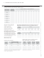
7.0 Appendix / Bilaga
Model / Modell
ΔT20 ΔT30 ΔT40 ΔT50 ΔT60 ΔT20 ΔT30 ΔT40 ΔT50 ΔT60
500
Normal 393 566 733 896 1056 1340 1930 2501 3057 3603
Boost 447 683 923 1166 1412 1524 2331 3150 3980 4817
600
Normal 467 729 1000 1278 1562 1592 2486 3412 4361 5330
Boost 607 939 1279 1625 1977 2072 3203 4363 5545 6744
600-12V
Normal 467 729 1000 1278 1562 1592 2486 3412 4361 5330
Boost 607 939 1279 1625 1977 2072 3203 4363 5545 6744
800
Normal 747 1077 1396 1707 2012 2550 3675 4763 5824 6864
Boost 845 1289 1738 2192 2649 2885 4397 5930 7478 9039
80S
Normal 304 455 605 755 905 1037 1552 2064 2576 3088
Boost 331 509 691 876 1062 1129 1737 2358 2989 3624
80D
Normal 421 624 824 1023 1221 1436 2129 2811 3490 4166
Boost 475 707 938 1169 1399 1621 2412 3200 3989 4773
Heat Output / Värmeutgång (Watts) Heat Output / Värmeutgång (Btu/h)
Heating Performance Data / Data för värmeprestanda
Temperature Difference / Temperaturskillnad (°C)
Fan Speed /
Fläkthastighet
Sound Levels / Ljudnivåer
Heat outputs tested in accordance with
BS 4856 Part 1 / Värmeutgång testad i
enlighet med BS 4856 del 1.
Flow Rate: 340 ltr/h (75 gal/h) /
Flödeshastighet: 340 l/h (75 gal/h).
Flow Rate Correction Factors /
Korrigeringsfaktorer för flödeshastighet:
455 ltr/h (100 gal/h) multiply output by 1.03 /
455 l/h (100 gal/h) multiplicera utgång med 1,03.
227 ltr/h (50 gal/h) multiply output by 0.96 /
227 l/h (50 gal/h) multiplicera utgång med 0,96.
113 ltr/h (25 gal/h) multiply output by 0.85 /
113 l/h (25 gal/h) multiplicera utgång med 0,85.
Test Pressure / Testtryck: 20 bar
Maximum Working Pressure /
Maximalt arbetstryck: 10 bar
Sound levels tested in accordance with EN 23741 / Ljudnivåer
testade i enlighet med EN 23741.
*Includes transformer / Transformator ingår.
Model /
Modell
Sound Pressures at 2.5m /
Ljudtryck vid 2,5 m (dBA)
500 25.7 38.1
600 26.4 37.2
600-12V 29.4 39.0
800 28.5 49.8
80S 24.5 31.4
80D 21.8 35.6
Normal Boost
Weight, Water Content and Motor Power /
Vikt, vatteninnehåll och motorkraft
Model /
Modell
Motor Power /
Motorkraft
(W)
Water Content /
Vatteninnehåll
(l)
Unit Weight /
Enhetsvikt
(kg)
500 25 0.26 4.3
600 40 0.30 5.0
600-12V* 40 0.30 7.9*
800 40 0.34 5.5
80S 13 0.17 3.83
80D 17 0.25 5.13
Approximate Hydraulic Resistance through Fan Convectors /
Ungefärligt hydrauliskt motstånd genom fläktkonvektorer
Litres/h
Liter/h
500
788
488
231
82
600
1046
625
326
95
600-12V
1046
625
326
95
800
911
544
258
82
80S
592
372
207
95
80D
613
439
295
176
455
340
227
113
mm wg
Litres/h
Liter/h
500
7.7
4.8
2.3
0.8
600
10.3
6.1
3.2
0.9
800
8.9
5.3
2.5
0.8
600-12V
10.3
6.1
3.2
0.9
80S
5.8
3.6
2.0
0.9
80D
6.0
4.3
2.9
1.7
455
340
227
113
kPa
08
KICKSPACE
®
500, 600, 600-12V, 800, 80S & 80D
KICKSPACE
®
500, 600, 600-12V, 800, 80S & 80D
INSTALLATION & OPERATING MANUAL /
KICKSPACE
®
500, 600, 600-12V, 800, 80S & 80D INSTALLATIONS- OCH ANVÄNDARHANDBOK
01.07.2018

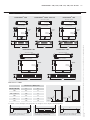
7.0 Appendix / Bilaga (continued / fortsättning...)
A
Fig. 2a Plinth opening - floor mounting /
Sockelöppning - golvmontering
FLOOR COVERING
/
GOLVSKYDD
FLOOR COVERING
/
GOLVSKYDD
80mm
80mm
Fig. 1
Dimensions / Mått
Model / Modell A B
Dimensions / Mått (mm)
500 466 93
600 & 600-12V 520 93
800 573 93
80S 530 80
80D 730 80
A = Width of cutout / Bredd på avstängningsenhet B = Height of cutout / Höjd för avstängningsenhet
KICKSPACE
®
800KICKSPACE
®
600 & 600-12VKICKSPACE
®
500
KICKSPACE
®
80DKICKSPACE
®
80S
B
A
Fig. 2b Plinth opening - plinth mounting /
Sockelöppning - sockelmontering
B
A
Fig. 2c Plinth opening - 80mm plinth height /
Sockelöppning - 80 mm sockelhöjd
B
496
101
309
82
36
129
322
25
54
67
93
12
24
View on arrow / Vy bakifrån
Cable entries /
Kabelingångar
Top view / Sett uppifrån
Mains cable
/ Nätkabel
Cable entry /
Kabelingångar
FRONT GRILLE / FRONTGALLER
432
44
72
36
560
301
123
40
123
25
21
14
24.5
80
View on arrow / Vy bakifrån
Cable entries /
Kabelingångar
Top view / Sett uppifrån
Mains cable
/ Nätkabel
Cable entry /
Kabelingångar
FRONT GRILLE / FRONTGALLER
602
44
72
36
301
123
40
123
25
21
14
24.5
760
80
View on arrow / Vy bakifrån
Cable entries /
Kabelingångar
Top view / Sett uppifrån
Mains cable
/ Nätkabel
Cable entry /
Kabelingångar
FRONT GRILLE / FRONTGALLER
550
101
54
93
67
12
24
25
129
36
82
309
376
View on arrow / Vy bakifrån
Cable entries /
Kabelingångar
Top view / Sett uppifrån
Mains cable
/ Nätkabel
Cable entry /
Kabelingångar
FRONT GRILLE / FRONTGALLER
101
603
54
93
67
12
24
25
129
36
82
309
447
View on arrow / Vy bakifrån
Cable entries /
Kabelingångar
Top view / Sett uppifrån
Mains cable
/ Nätkabel
Cable entry /
Kabelingångar
FRONT GRILLE / FRONTGALLER
09
KICKSPACE
®
500, 600, 600-12V, 800, 80S & 80D
KICKSPACE
®
500, 600, 600-12V, 800, 80S & 80D
INSTALLATION & OPERATING MANUAL /
KICKSPACE
®
500, 600, 600-12V, 800, 80S & 80D INSTALLATIONS- OCH ANVÄNDARHANDBOK
01.07.2018

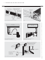
7.0 Appendix / Bilaga (continued / fortsättning...)
Grille securing screw
/ Fästskruv för galler
Grille securing screw
/ Fästskruv för galler
Fig. 3 Front view of unit / Enheten sett framifrån
Unit securing screw
/ Fästskruv för enhet
Unit securing screw
/ Fästskruv för enhet
Switch for fan /
Brytare för fläkt
Boost
Off / Av
Normal
Heating/fan only switch / Brytare
för uppvärmning/endast fläkt
Isolating valves /
Isoleringsventiler
Flexible pipes
/ Flexibla rör
Fig. 4
300
400
WALL / VÄGG
Fig. 5a Left hand view - suggestion only /
Sett från vänster - endast förslag
250
100
WALL / VÄGG
Fig. 5b Right hand view - suggestion only /
Sett från höger - endast förslag
0
1
°C
30
25
20
15
10
5
N
N
2
5
6
0
1
°C
30
25
20
15
10
5
N
N
2
5
6
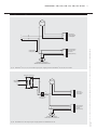
N
TP
Fig. 6 Electrical connection / Elektrisk anslutning
NOTE: The electrical installation must
be done by authorised electrician /
Obs! Elektrisk installation måste
utföras av behörig elektriker
T-2
N
P-6
Room thermostat / Rumstermostat
Pull relief /
Dragavlastning
Wall socket / Vägguttag
Double-sided wall plug / Dubbelsidig väggkontakt
Colour codes / Färgkoder
N = Blue / Blå
T = Brown / Brun
P = Black / Svart
MYSON KICKSPACE
®
10
KICKSPACE
®
500, 600, 600-12V, 800, 80S & 80D
KICKSPACE
®
500, 600, 600-12V, 800, 80S & 80D
INSTALLATION & OPERATING MANUAL /
KICKSPACE
®
500, 600, 600-12V, 800, 80S & 80D INSTALLATIONS- OCH ANVÄNDARHANDBOK
01.07.2018

7.0 Appendix / Bilaga (continued / fortsättning...)
Fan Selector
Switch / Brytare
för fläktväljare
Fan Only/Heating
Switch / Brytare
för endast
fläkt/uppvärmning
LOW LIMIT THERMOSTAT
/ NEDRE GRÄNS FÖR TERMOSTAT
MOTOR
Chassis Earth /
Chassijordning
br
bl
L
N
g/y
bl
y
r
bl bl
Fig. 7a KICKSPACE
®
500, 600, 800, 80S & 80D wiring diagram / Kopplingsschema för KICKSPACE
®
500, 600, 800, 80S och 80D
Mains Supply 240V
/ Nätuttag 240 V
Transformer / Transformator
Connector Block
/ Kontaktblock
MOTOR
br
bl
L
N
bl
br
Fan Selector
Switch / Brytare
för fläktväljare
Fan Only/Heating
Switch / Brytare
för endast
fläkt/uppvärmning
LOW LIMIT THERMOSTAT
/ NEDRE GRÄNS FÖR TERMOSTAT
Fig. 7b KICKSPACE
®
600-12V wiring diagram / Kopplingsschema för KICKSPACE
®
600-12V
11
KICKSPACE
®
500, 600, 600-12V, 800, 80S & 80D
KICKSPACE
®
500, 600, 600-12V, 800, 80S & 80D
INSTALLATION & OPERATING MANUAL /
KICKSPACE
®
500, 600, 600-12V, 800, 80S & 80D INSTALLATIONS- OCH ANVÄNDARHANDBOK
01.07.2018

Product code and serial number location
/ Plats för produktkod och -serienummer
Product Serial Number / Produktserienummer:
COMPLETE HEATING SOLUTIONS
01.07.18
Sanova AB, Sockerbruksgatan 3C,
531 40 Lidköping, SWEDEN
Tel: 0510-485890 Email: [email protected]
www.sanova.se
-
 1
1
-
 2
2
-
 3
3
-
 4
4
-
 5
5
-
 6
6
-
 7
7
-
 8
8
-
 9
9
-
 10
10
-
 11
11
-
 12
12


Myson Kickspace 500 Installation & Operating Manual
- Typ
- Installation & Operating Manual
- Denna manual är också lämplig för
på andra språk
- English: Myson Kickspace 500