
Manual
EN
Handleiding
NL
Manuel
FR
Anleitung
DE
Manual
ES
Användarhandbok
SE
Appendix
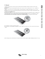
Solar Module


Copyrights 2007 Victron Energy B.V.
All Rights Reserved
This publication or parts thereof may not be reproduced in any form, by any method, for any purpose.
For conditions of use and permission to use this manual for publication in other than the English language, contact Victron Energy B.V.
VICTRON ENERGY B.V. MAKES NO WARRANTY, EITHER EXPRESSED OR IMPLIED, INCLUDING BUT NOT LIMITED TO ANY
IMPLIED WARRANTIES OF MERCHANTABILITY OR FITNESS FOR A PARTICULAR PURPOSE, REGARDING THESE VICTRON
ENERGY PRODUCTS AND MAKES SUCH VICTRON ENERGY PRODUCTS AVAILABLE SOLELY ON AN “AS IS” BASIS.
IN NO EVENT SHALL VICTRON ENERGY B.V. BE LIABLE TO ANYONE FOR SPECIAL, COLLATERAL, INCIDENTAL, OR
CONSEQUENTIAL DAMAGES IN CONNECTION WITH OR ARISING OUT OF PURCHASE OR USE OF THESE VICTRON ENERGY
PRODUCTS. THE SOLE AND EXCLUSIVE LIABILITY TO VICTRON ENERGY B.V., REGARDLESS OF THE FORM OF ACTION,
SHALL NOT EXCEED THE PURCHASE PRICE OF THE VICTRON ENERGY PRODUCTS DESCRIBED HERE IN.
Victron Energy B.V. reserves the right to revise and improve its products as it sees fit. This publication describes the state of this
product at the time of its publication and may not reflect the product at all times in the future


1
EN NL FR DE ES SE Appendix
Contents
1. Purpose of this guide
2. General
3. Safety precaution for installing a solar photovoltaic system
4. Mechanical Installation
4.1 Selecting the location
4.2 Selecting the proper support frame
4.3 Ground mount
4.4 Roof mount
4.5 Pole mount
4.6 General installation
5. Electrical Installation
5.1 Grid-connected electrical system
5.2 Grounding
5.3 General installation
6. Commission and Maintenance
6.1 Blocking diodes and bypass diodes
6.2 Testing, commissioning and troubleshooting
6.3 Troubleshooting low voltages
6.4 Maintenance
7. Disclaimer of Liability

2
1. PURPOSE OF THIS GUIDE
This guide contains information regarding the installation and safe handling.
Installers must read and understand the guide before installation. Any questions, please contact our sales department for further
explanations. The installer should conform to all safety precautions in the guide and local codes when installing a module.
Before installing a solar photovoltaic system, installers should become familiar with the mechanical and electrical requirement for such a
system. Keep this guide in a safe place for future reference (care and maintenance) and in case of sale or disposal of the modules.

3
EN NL FR DE ES SE Appendix
2. General
Installing solar photovoltaic systems may require specialized skills and knowledge. Installation should be performed only by
qualified persons.
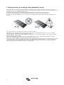
Each module comes with a permanently attached junction. We can provide customers with fitted cables for ease of installation if
desired.
Installers should assume the risk of all injury that might occur during installation, including, without limitation, the risk of electric
shock.
One individual module may generate DC voltages greater than 30 volts when exposed to direct sunlight. Contact with a DC voltage
of 30V or more is potentially hazardous.
Do not disconnect under load.
Photovoltaic solar modules convert light energy to direct-current electrical energy. They are designed for outdoor use. Modules may
be ground mounted, mounted on roof tops, vehicles or boats. Proper design of support structures is responsibility of the system
designers and installers. Use of mounting holes is suggested in a following paragraph.
Do not attempt to disassemble the modules, and do not remove any attached nameplates or components from the modules.
Do not apply paint or adhesive to module top surface.
Do not use mirrors or other magnifiers to artificially concentrate sunlight on the modules. Do not expose back-sheet foils directly to
sunlight.
When installing the system, abide with all local, regional and national statutory regulations. Obtain a building permit where necessary.

4
3. Safety precaution for installing a solar photovoltaic system
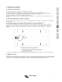
Solar modules produce electrical energy when light shines on their front surface. The DC voltage may exceed 30V. If modules are
connected in series, the total voltage is equal to the sum of the individual module voltages. If modules are connected in parallel, the total
current is equal to the sum of individual module currents.
Keep children well away from the system while transporting and installing mechanical and electrical components.
Completely cover the module with an opaque material during installation to keep electricity from being generated.
Do not wear metallic rings, watchbands, ear, nose, lip rings or other metallic devices while installing or troubleshooting photovoltaic
systems.
Use only insulated tools that are approved for working on electrical installations.
Abide with the safety regulations for all other components used in the system, including wiring and cables, connectors, charging
regulators, inverters, storage batteries and rechargeable batteries, etc.
Use only equipment, connectors, wiring and support frames suitable for a solar electric system. Always use the same type of module
within a particular photovoltaic system.
The electrical characteristics are within ±10 percent of the indicated values of Isc, Voc, and Pmax under standard test conditions
(irradiance of 100mW/cm2, AM 1.5 spectrums, and a cell temperature of 25°C (77°F))
Under normal outdoor conditions the module will produce current and voltages that are different than those listed in the date sheet. Data
sheet values are values expected at standard test conditions. Accordingly, during system design, values of short-circuit current and
open-circuit voltage should be multiplied by a factor of 1.25 when determining component voltage ratings, conductor capacity, fuse
ratings and size of controls connected to the modules or system output.

5
EN NL FR DE ES SE Appendix
4. Mechanical Installation
4.1 Selecting the location
Select a suitable location for installing the modules.
The modules should be facing south in northern latitudes and north in southern latitudes.
For detailed information on the best elevation tilt angle for the installation, refer to standard solar photovoltaic installation guides or a
reputable solar installer or systems integrator.
The module should not be shaded at any time of the day.
Do not use module near equipment or in locations where flammable gases can be generated or collected.
4.2 Selecting the proper support frame
Always observe the instructions and safety precautions included with the support frames to be used with the modules.
Do not attempt to drill holes in the glass surface of the modules. To do so will void the warranty.
Do not drill additional mounting holes in the frame of the modules. Doing so will void the warranty.
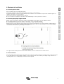
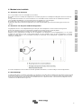
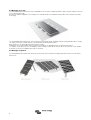
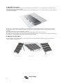
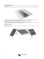
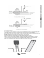
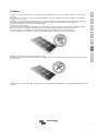
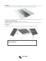
Modules must be securely attached to the mounting structure using four mounting points for normal installation. If additional wind or
snow-loads are anticipated for this installation, additional mounting points are also used. The details please see the below drawing.
Load calculations are left to the system designers or installers.
The support module mounting structure must be made of durable, corrosion-resistant and UV-resistant material.
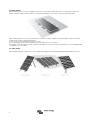
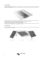
4.3 Ground mount
Select the height of the mounting system to prevent the lowest edge of the module from being covered by snow for a long time in winter
in areas that experience heavy snowfalls. In addition, assure the lowest portion of the module is placed high enough so that it is not
shaded by plants or trees or damaged by sand and stone driven by wind.

6
4.4 Roof mount
When installing a module on a roof or building, ensure that it is securely fastened and cannot fall as a result of wind or snow loads.
Provide adequate ventilation under a module for cooling (10cm minimum air space between module and mounting surface).
When installing module on a roof, ensure that the roof construction is suitable. In addition, any roof penetration required to mount the
module must be properly sealed to prevent leaks.
In some cases, a special support frame may be necessary.
The roof installation of solar modules may affect the fire-proofing of the house construction.
The modules are rated fire Class C, and are suitable for mounting over a class A roof. Do not install modules on a roof or building during
strong winds in case of accidents.
4.5 Pole mount
When installing a module on a pole, choose a pole and module mounting structure that will withstand anticipated winds for the area.

7
EN NL FR DE ES SE Appendix
4.6 General installation
Module mounting must use the pre-drilled mounting holes in the frame.
The most common mounting is achieved by mounting the module using the four symmetry points close to the inner side on module
frames.
If excessive wind or snow loads are expected, all eight mounting holes must be used
Do not lift the module by grasping the module’s junction box or electrical leads.
Do not stand or step on module.
Do not drop module or allow objects to fall on module.
To avoid glass breakage, do not place any heavy objects on the module.
Do not set the module down hard on any surface.
Inappropriate transport and installation may break module.

8
5.
Electrical Installation
This guide describes some of the most important typical uses as representative examples.
5.1 Grid-connected electrical system
The DC electrical energy generated by photovoltaic systems may also be converted to AC and connected to a utility grid system. As
local utilities’policies on connecting renewable energy systems to their grids vary from region to region.
Consult a qualified system designer or integrator to design such a system. Permits are normally required for installing such a system
and the utility must formally approve and inspect such a system before it can be accepted
5.2 Grounding
The module frame must be properly grounded. The grounding wire must be properly fastened to the module frame to assure good
electrical contact. Use the recommended type, or an equivalent, connector for this wire.
If the support frame is made of metal, the surface of the frame must be electroplated and have excellent conductivity.
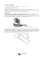
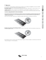
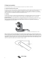
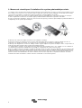
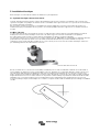
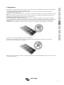
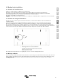
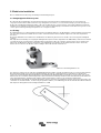
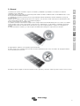
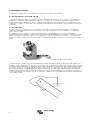
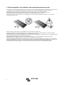
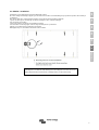
We recommend the lay-in lug(Cat. No. GBL4-DBT is recommended by producer) when grounding. First strip 16mm insulating jacket
from the end of the ground wire carefully to avoid nicking or cutting conductors, insert the wire to the feet of the lug (see the picture), and
screw down the slotted screw. Be careful not to damage the wire core. And then tighten up the screw.
Insert ground wire here
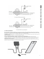
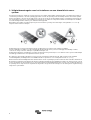
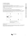
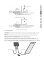
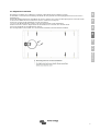
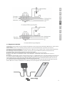
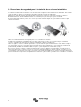
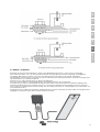
Next, assemble the recommended ILSCO grounding lug to the aluminum frame using stainless steel M3 or M5 screw and hardware as
shown below. Note: there are two different size grounding holes, the smaller of which is being phased out. Further, buildup of hardware
for mounting the grounding lug are the same—except for the M3 screw, an added lat washer is mounted directly under the M3 screw
head. The star washer is fitted directly under the grounding lug and makes electrical contact by penetrating the anodized coating of the
aluminum frame, The screw assembly is further fitted with a lat washer, then a split lock washer and finally a nut to secure the entire
assembly, as shown. Recommended torque of M3 or M5 screw assembly is 0.8NM or 1.5 NM.
.

9
EN NL FR DE ES SE Appendix
5.3 General installation
Do not use modules of different configurations in the same system. The max. number of module (N) = Vmax system / [Voc(at STC)].
Several modules are connected in series and then in parallel to form a PV array, especially for application with a high operation voltage.
If modules are connected in series, the total voltage is equal to the sum of individual voltages.
For applications requiring high currents, several photovoltaic modules can be connected in parallel; the total current is equal to the sum
of individual currents.
Module is supplied with connectors to use for system electrical connections.
Consult rated local wiring regulations to determine system wire size, type, and temperature.
The cross section area of cable and the capacity of connector must be selected to suit the maximum system short circuit
current(Recommended cross section area of cable is 4mm2 for a single module and rated current of a connector is larger than 10A ),
otherwise the cable and connector will be overheated under large current. Please note that the upper limit temperature of cable is
≥85oC,and the connector is ≥105oC.
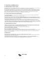
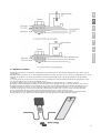
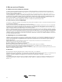
The junction box has a breather port. The breather port must be mounted facing down and can not be exposed to rain. Therefore, the
junction box must be on the higher side of the module when it is mounted.

10
6. Commission and Maintenance
6.1 Blocking diodes and bypass diode
Blocking diodes prevent current flowing from the battery to the module when no electricity is being generated. It is recommended to use
blocking diodes when a charging regulator is not used. Your specialist dealer can advise you the suitable types.
In systems with more than two modules in series, high reverse current can flow through cells that are shaded partially or totally when
part of a module is shaded and the rest is exposed to the sun. These currents can cause the affected cells to get very hot and could
even damage the module. To protect module from such high reverse currents, by-pass diodes are used in module. All modules have
bypass diodes already integrated in the junction box. In the unlikely event of diode failure, a replacement can easily be made.
Protect yourself from electricity shocks while debugging or maintaining the solar power system.
6.2 Testing, commissioning and troubleshooting
Test all electrical and electronic components of the system before using it. Follow the instructions in the guides supplied with the
components and equipment.
Testing modules connected in series before they are connected to system.
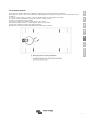
Check the open-circuit voltage of every series module by a digital multi-meter (fluke 170 series are recommended). The measured
values should correspond to the sum of the open-circuit voltage of the individual module. You will find the rated voltage in the technical
specifications of the type of the module used. If the measured value is significantly lower than the expected value, please proceed as
described under “Troubleshooting an excessively low voltage”.
Check the short-circuit current of every series circuit. It can be measured directly by a digital multi-meter (Fluke 170 series are
recommended) connected in the two terminals of series circuit or module, or with any load such as PV illumination to make a rough
measurement. Attention, the rated scale of the ammeter or the rated current of load should be more than 1.25 times of the rated short-
circuit current of series module. You will find the rated current in the technical specifications of the type of module used. The measured
value can vary significantly, depending on weather conditions, the time of day and shading of the module.
6.3 Troubleshooting low voltages
Identify the commonly low voltage and excessively low voltage. Commonly the low voltage mentioned here is the decrease of open-
circuit voltage of the module, which is caused by the temperature rising of solar cells or lower irradiance. Excessively low voltage is
typically caused by improper connections at the terminals or defective bypass diodes
First, check all wiring connections to make sure it is not open-circuit or is not connection well.
Check the open-circuit voltage of each module:
Fully cover the modules with an opaque material.
Disconnect the wiring at both terminals of the modules.
Remove the opaque material from the module to be checked and measure the open-circuit voltage at its terminals.
If the measured voltage is only half of the rated, this indicates a defective bypass diode. Refer to ‘Testing and replacing bypass diodes’.
In the case of not very low irradiance, if the voltage across the terminals differs from the rated value by more than 5 percent, this
indicates a bad electrical connection.
6.4 Maintenance
We recommends the following maintenance in order to ensure optimum performance of the module:
Clean the glass surface of the module as necessary. Always use water and a soft sponge or cloth for cleaning. A mild, non-abrasive
cleaning agent can be used to remove stubborn dirt.
Check the electrical and mechanical connections every six months to verify that they are clean, secure and undamaged.
If any problem arises, have them investigated by a competent specialist. Attention, observe the maintenance instructions for all
components used in the system, such as support frames, charging regulators, inverters, batteries etc.

11
EN NL FR DE ES SE Appendix
7. Disclaimer of Liability
Because the use of this manual and the conditions or methods of installation, operation, use and maintenance of photovoltaic (PV)
product are beyond our control, We does not accept responsibility and expressly disclaims liability for loss, damage, or expense
arising out of or in any way connected with such installation, operation, use or maintenance.
No responsibility is assumed by us for any infringement of patents or other rights of third parties, which may result from use of the
PV product.
No license is granted by implication or otherwise under any patent or patent rights.
The information in this manual is based on our knowledge and experience and is believed to be reliable; but such information
including product specification (without limitations) and suggestions do not constitute a warranty, expresses or implied. We reserve
the right to change the manual, the PV produce, the specifications, or product information sheets without prior notice.


1
EN NL FR DE ES SE Appendix
Inhoud
1. Doel van deze handleiding
2. Algemeen
3. Veiligheidsmaatregelen voor het installeren van een fotovoltaïsch zonne-
systeem
4. Mechanische installatie
4.1 Selecteren van de locatie
4.2 Selecteren van het juiste ondersteuningsframe
4.3 Grondmontage
4.4 Dakmontage
4.5 Paalmontage
4.6 Algemene installatie
5. Elektrische installatie
5.1 Net- gekoppeld elektrosysteem
5.2 Aarding
5.3 Algemene installatie
6. Commissie en onderhoud
6.1 Blocking diodes en bypass- diodes
6.2 Testen, inbedrijfstelling en probleemoplossing
6.3 Problemen met lage voltages
6.4 Onderhoud
7. Disclaimer

2
1. Doel van deze handleiding
Deze handleiding bevat informatie over de installatie en het veilig hanteren.
De installateur moet deze handleiding lezen en begrijpen voor de installatie. Als u vragen heeft kunt u contact opnemen met onze
afdeling verkoop voor verdere uitleg. Bij het installeren van de module moet de installateur voldoen aan alle veiligheidsvoorschriften uit
deze handleiding en aan de lokale codes. Vóór de installatie van een fotovoltaïsch zonne-systeem moet de installateur vertrouwd raken
met de mechanische en elektrische eisen van een dergelijk systeem. Bewaar deze handleiding op een veilige plaats voor toekomstige
referentie (zorg en onderhoud) en in geval van verkoop of verwijdering van de modules.

3
EN NL FR DE ES SE Appendix
2. Algemeen
Voor het installeren van fotovoltaïsche systemen kan het vereist zijn om over specialistische vaardigheden en kennis te beschikken.
De installatie moet alleen worden uitgevoerd door gekwalificeerde personen.
Elke module wordt geleverd met een vastgemonteerde kruising. We kunnen klanten, indien gewenst, voorzien van kabels voor een
gemakkelijke installatie.
Installateurs dragen zelf het risico van alle letsels die mogelijk kunnen voorkomen tijdens de installatie, zoals het risico op een
elektrische schok.
Elke module kan individueel DC spanningen produceren van meer dan 30 volt, wanneer het wordt blootgesteld aan direct zonlicht.
Contact met een DC spanning van 30V of meer kan gevaarlijk zijn.
Verbreek de verbinding niet wanneer de module onder belasting is.
Fotovoltaïsche zonnepanelen zetten lichtenergie om in elektrische energie. Ze zijn ontworpen voor gebruik buitenshuis. De modules
kunnen op de grond, op daken, auto’s of boten worden gemonteerd. Het is de verantwoordelijkheid van de systeemontwerpers en
installateurs om te zorgen voor een goede vormgeving van ondersteunende structuren. Het gebruik van montagegaten wordt in de
volgende paragraaf behandeld.
Probeer niet om de modules te demonteren en verwijder geen bijgevoegde naamplaten of onderdelen van de modules.
Breng geen verf of lijm aan op de bovenkant van de module.
Gebruik geen spiegels of lenzen om kunstmatig zonlicht te concentreren op de modules. Het folie op achterkant van de panelen niet
aan direct zonlicht blootstellen.
Bij het installeren van het systeem moet u zich houden aan lokale, regionale en nationale wettelijke voorschriften, bijvoorbeeld, indien
nodig, het verkrijgen van een bouwvergunning.

4
3. Veiligheidsmaatregelen voor het installeren van een fotovoltaïsch zonne-
systeem
Zonnepanelen produceren elektrische energie als licht op de voorzijde schijnt. De DC spanning kan 30V overschrijden. Als modules in
serie worden geschakeld, is de totale spanning gelijk aan de som van de spanning van de afzonderlijke modules. Als modules parallel
worden geschakeld, is de totale stroom gelijk aan de som van de stroom van de afzonderlijke modules. Houd kinderen uit de buurt van
het systeem tijdens het vervoer en de installatie van mechanische en elektrische componenten. Bedek de module tijdens de installatie
met ondoorzichtig materiaal, zodat er geen elektriciteit wordt opgewekt.
Draag tijdens de installatie of probleemoplossing van het fotovoltïsch systeem geen metalen ringen, horlogebanden, oor-, neus- lip
ringen of andere metalen voorwerpen.
Gebruik alleen geïsoleerde gereedschappen die zijn goedgekeurd voor het werken aan elektrische installaties.
Volg de veiligheidsvoorschriften voor alle onderdelen die worden gebruikt in het systeem, met inbegrip van bedrading en kabels,
connectoren, charge controllers, batterijen en oplaadbare batterijen, enz.
Gebruik alleen apparatuur, aansluitingen en ondersteunende frames die geschikt zijn voor een elektrisch zonne-systeem. Gebruik altijd
hetzelfde type module binnen een bepaald fotovoltaïsch systeem.
De elektrische eigenschappen zijn binnen ± 10 procent van de aangegeven waarden van ISC, VOC en Pmax onder standaard
testomstandigheden (bestralingssterkte van 100mW/cm2, AM 1.5 spectrum en een cel temperatuur van 25 ° C (77 ° F))
Onder normale buitenomstandigheden zal de module andere stroom en spanningen produceren dan die staan vermeld in de datasheet.
De waarden in de datasheet zijn waarden die worden verwacht bij standaard testomstandigheden. Tijdens het ontwerp van het systeem
moeten de waarden van de kortsluitstroom en open-klem spanning vermenigvuldigd worden met een factor van 1.25 bij het bepalen van
de spanning van de componenten, de capaciteit van de geleiders, de grootte van de zekeringen en de omvang van de regelaars die zijn
aangesloten op de modules.
Sidan laddas...
Sidan laddas...
Sidan laddas...
Sidan laddas...
Sidan laddas...
Sidan laddas...
Sidan laddas...
Sidan laddas...
Sidan laddas...
Sidan laddas...
Sidan laddas...
Sidan laddas...
Sidan laddas...
Sidan laddas...
Sidan laddas...
Sidan laddas...
Sidan laddas...
Sidan laddas...
Sidan laddas...
Sidan laddas...
Sidan laddas...
Sidan laddas...
Sidan laddas...
Sidan laddas...
Sidan laddas...
Sidan laddas...
Sidan laddas...
Sidan laddas...
Sidan laddas...
Sidan laddas...
Sidan laddas...
Sidan laddas...
Sidan laddas...
Sidan laddas...
Sidan laddas...
Sidan laddas...
Sidan laddas...
Sidan laddas...
Sidan laddas...
Sidan laddas...
Sidan laddas...
Sidan laddas...
Sidan laddas...
Sidan laddas...
Sidan laddas...
Sidan laddas...
Sidan laddas...
Sidan laddas...
Sidan laddas...
Sidan laddas...
Sidan laddas...
Sidan laddas...
Sidan laddas...
Sidan laddas...
Sidan laddas...
Sidan laddas...
Sidan laddas...
Sidan laddas...
Sidan laddas...
Sidan laddas...
-
 1
1
-
 2
2
-
 3
3
-
 4
4
-
 5
5
-
 6
6
-
 7
7
-
 8
8
-
 9
9
-
 10
10
-
 11
11
-
 12
12
-
 13
13
-
 14
14
-
 15
15
-
 16
16
-
 17
17
-
 18
18
-
 19
19
-
 20
20
-
 21
21
-
 22
22
-
 23
23
-
 24
24
-
 25
25
-
 26
26
-
 27
27
-
 28
28
-
 29
29
-
 30
30
-
 31
31
-
 32
32
-
 33
33
-
 34
34
-
 35
35
-
 36
36
-
 37
37
-
 38
38
-
 39
39
-
 40
40
-
 41
41
-
 42
42
-
 43
43
-
 44
44
-
 45
45
-
 46
46
-
 47
47
-
 48
48
-
 49
49
-
 50
50
-
 51
51
-
 52
52
-
 53
53
-
 54
54
-
 55
55
-
 56
56
-
 57
57
-
 58
58
-
 59
59
-
 60
60
-
 61
61
-
 62
62
-
 63
63
-
 64
64
-
 65
65
-
 66
66
-
 67
67
-
 68
68
-
 69
69
-
 70
70
-
 71
71
-
 72
72
-
 73
73
-
 74
74
-
 75
75
-
 76
76
-
 77
77
-
 78
78
-
 79
79
-
 80
80


Victron energy 2497152 Bruksanvisning
- Typ
- Bruksanvisning
- Denna manual är också lämplig för
på andra språk
Relaterade papper
-
Victron energy SmartSolar MPPT 75/15 Bruksanvisning
-
-
-
-
-
-
-