
G
Digital Sound Projector
Projecteur Numérique de Son
Quick Reference Guide
Guide de référence rapide
Kurzanleitung
Snabbreferensguide
Guida rapida
Guía de referencia rápida
Snelgids
Краткое руководство
SWK-W16
For more detailed information, refer to the Owner’s Manual on the
CD-ROM.
Caution: Do not attempt to play this CD-ROM in an audio player.
English
Pour de plus amples informations, reportez-vous au Mode d’emploi
qui se trouve sur le CD-ROM.
Attention : N’essayez pas de lire ce CD-ROM dans un lecteur
audio.
Français
Ausführlichere Informationen finden Sie in der Bedienungsanleitung
auf der CD-ROM.
Achtung: Versuchen Sie nicht, diese CD-ROM in einem
CD-Player abzuspielen.
Deutsch
För detaljerad information, se bruksanvisningen på CD-ROM-skivan.
Observera: Försök ej att spela upp denna CD-ROM-skiva på en
cd-ljudspelare.
Svenska
Per maggiori informazioni dettagliate fare riferimento al Manuale di
istruzioni sul CD-ROM.
Attenzione: non riprodurre il CD-ROM in un lettore audio.
Italiano
Para obtener más información, consulte el Manual de instrucciones
que encontrará en el CD-ROM.
Precaución: No intente reproducir este CD-ROM en un
reproductor de audio.
Español
Raadpleeg de gebruiksaanwijzing op de CD-ROM voor meer
gedetailleerde informatie.
Let op: probeer deze CD-ROM niet af te spelen in een
audiospeler.
Nederlands
Более подробная информация приведена в Инструкции по
эксплуатации на диске CD-ROM.
Предостережение: Не пытайтесь воспроизвести этот
CD-ROM на аудиоплеере.
Русский

2 En
1 To assure the finest performance, please read this manual carefully. Keep it in a safe place for
future reference.
2 Install this sound system in a well ventilated, cool, dry, clean place - away from direct sunlight,
heat sources, vibration, dust, moisture, and/or cold. For proper ventilation, allow the following
minimum clearances.
Top: 5 cm, Rear: 5 cm, Sides: 5 cm
3 Locate this unit away from other electrical appliances, motors, or transformers to avoid humming
sounds.
4 Do not expose this unit to sudden temperature changes from cold to hot, and do not locate this unit
in an environment with high humidity (i.e. a room with a humidifier) to prevent condensation
inside this unit, which may cause an electrical shock, fire, damage to this unit, and/or personal
injury.
5 Avoid installing this unit where foreign object may fall onto this unit and/or this unit may be
exposed to liquid dripping or splashing. On the top of this unit, do not place:
– Other components, as they may cause damage and/or discoloration on the surface of this unit.
– Burning objects (i.e. candles), as they may cause fire, damage to this unit, and/or personal
injury.
– Containers with liquid in them, as they may fall and liquid may cause electrical shock to the
user and/or damage to this unit.
6 Do not cover this unit with a newspaper, tablecloth, curtain, etc. in order not to obstruct heat
radiation. If the temperature inside this unit rises, it may cause fire, damage to this unit, and/or
personal injury.
7 Do not plug in this unit to a wall outlet until all connections are complete.
8 Do not operate this unit upside-down. It may overheat, possibly causing damage.
9 Do not use force on switches, knobs and/or cords.
10 When disconnecting the power cable from the wall outlet, grasp the plug; do not pull the cable.
11 Do not clean this unit with chemical solvents; this might damage the finish. Use a clean, dry cloth.
12 Only voltage specified on this unit must be used. Using this unit with a higher voltage than
specified is dangerous and may cause fire, damage to this unit, and/or personal injury. Yamaha will
not be held responsible for any damage resulting from use of this unit with a voltage other than
specified.
13 Be sure to connect to an appropriate outlet with a protective grounding connection. Improper
grounding can result in electrical shock, damage to the device(s), or even fire.
14 To prevent damage by lightning, keep the power cable and outdoor antennas disconnected from a
wall outlet or this unit during a lightning storm.
15 Do not attempt to modify or fix this unit. Contact qualified Yamaha service personnel when any
service is needed. The cabinet should never be opened for any reasons.
16 When not planning to use this unit for long periods of time (i.e. vacation), disconnect the AC power
plug from the wall outlet.
17 Be sure to refer to the “Troubleshooting” section of the Owner’s Manual on the CD-ROM for
common operating errors before concluding that this unit is faulty.
18 Before moving this unit, press A to set it to standby mode and disconnect the AC power plug from
the wall outlet.
19 Condensation will form when the surrounding temperature changes suddenly. Disconnect the
power cable from the outlet, then leave this unit alone.
20 When using this unit for a long time, this unit may become warm. Turn the power off, then leave
this unit alone for cooling.
21 Install this unit near the AC outlet and where the AC power plug can be reached easily.
22 The batteries shall not be exposed to excessive heat such as sunshine, fire or the like. When you
dispose of batteries, follow your regional regulations.
23 Excessive sound pressure from earphones and headphones can cause hearing loss.
24 Keep the product out of reach of children to avoid them swallowing small parts.
CAUTION: READ THIS BEFORE OPERATING YOUR UNIT.
This unit is not disconnected from the AC power source as long as it is connected to the wall
outlet, even if this unit itself is turned off by A. This state is called the standby mode. In this
state, this unit is designed to consume a very small quantity of power.
WARNING
TO REDUCE THE RISK OF FIRE OR ELECTRIC SHOCK, DO NOT EXPOSE THIS UNIT
TO RAIN OR MOISTURE.
Do not use this unit within 22 cm (9 inches) of persons with a heart pacemaker implant or
defibrillator implant.
Radio waves may affect electro-medical devices.
Do not use this unit near medical devices or inside medical facilities.
The name plate for SWK-W16 is located on the bottom of the unit.
English

En 3
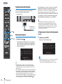
■ Notes on remote controls and batteries
• Do not spill water or other liquids on the remote control.
• Do not drop the remote control.
• Do not leave or store the remote control in the following conditions:
– places of high humidity, such as near a bath
– places of high temperatures, such as near a heater or stove
– places of extremely low temperatures
– dusty places
• Insert the battery according to the polarity markings (+ and -).
• Change all batteries if you notice the following conditions:
– the operation range of the remote control narrows
• If the batteries run out, immediately remove them from the remote control to prevent an explosion or
acid leak.
• If you find leaking batteries, discard the batteries immediately, taking care not to touch the leaked
material. If the leaked material comes into contact with your skin or gets into your eyes or mouth,
rinse it away immediately and consult a doctor. Clean the battery compartment thoroughly before
installing new batteries.
• Do not use old batteries together with new ones. This may shorten the life of the new batteries or
cause old batteries to leak.
• Do not use different types of batteries (such as alkaline and manganese batteries) together. Danger of
explosion may happen if batteries are incorrectly replaced. Specification of batteries may be different
even though they look the same.
• Before inserting new batteries, wipe the compartment clean.
• Keep batteries away from children. If a battery is accidentally swallowed, contact your doctor
immediately.
• When not planning to use the remote control for long periods of time, remove the batteries from the
remote control.
• Do not charge or disassemble the supplied batteries.
■ For U.K. customers
If the socket outlets in the home are not suitable for the plug supplied with this appliance, it
should be cut off and an appropriate 3 pin plug fitted. For details, refer to the instructions
described below.
The plug severed from the mains lead must be destroyed, as a plug with bared flexible cord is
hazardous if engaged in a live socket outlet.
■ Special Instructions for U.K. Model
Information for Users on Collection and Disposal of Old
Equipment and Used Batteries
These symbols on the products, packaging, and/or accompanying documents mean that
used electrical and electronic products and batteries should not be mixed with general
household waste.
For proper treatment, recovery and recycling of old products and used batteries, please
take them to applicable collection points, in accordance with your national legislation
and the Directives 2002/96/EC and 2006/66/EC.
By disposing of these products and batteries correctly, you will help to save valuable
resources and prevent any potential negative effects on human health and the
environment which could otherwise arise from inappropriate waste handling.
For more information about collection and recycling of old products and batteries,
please contact your local municipality, your waste disposal service or the point of sale
where you purchased the items.
[Information on Disposal in other Countries outside the European
Union]
These symbols are only valid in the European Union. If you wish to discard these items,
please contact your local authorities or dealer and ask for the correct method of disposal.
Note for the battery symbol (bottom two symbol examples):
This symbol might be used in combination with a chemical symbol. In this case it
complies with the requirement set by the Directive for the chemical involved.
Note
IMPORTANT
THE WIRES IN MAINS LEAD ARE COLOURED IN ACCORDANCE WITH THE
FOLLOWING CODE:
Blue: NEUTRAL
Brown: LIVE
As the colours of the wires in the mains lead of this apparatus may not correspond with the
coloured markings identifying the terminals in your plug, proceed as follows:
The wire which is coloured BLUE must be connected to the terminal which is marked with the
letter N or coloured BLACK. The wire which is coloured BROWN must be connected to the
terminal which is marked with the letter L or coloured RED.
Making sure that neither core is connected to the earth terminal of the three pin plug.
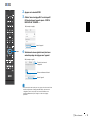
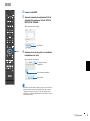
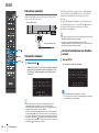
To view the Owner’s Manual, click on “English” in the screen displayed automatically when you
insert the CD-ROM into your PC, or click on the model name if the screen to select models is
displayed, and then click on “English” in the next screen. Then, follow the onscreen instructions.
If the screen is not displayed automatically, open the “index.html” in the CD-ROM.
The Owner’s Manual contained in the CD-ROM can be downloaded from the following website:
URL : http://download.yamaha.com/

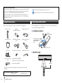
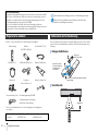
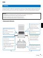
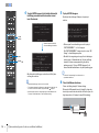
4 En Supplied accessories
Before connecting, make sure you have received all of the following items.
* The shape of the power cable plug varies depending on where the unit was
purchased.
Before installing batteries or using the remote control, be sure to read battery and
remote control precautions in this booklet.
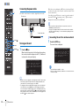
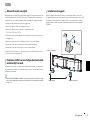
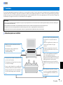
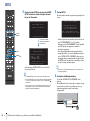
About this Quick Reference Guide
The Quick Reference Guide provides instructions for connecting a TV and BD/DVD
player to the unit, applying settings, and playing content. For more information on
operations, refer to the Owner’s Manual in the supplied CD-ROM.
Read the safety instructions described in this booklet before using the unit. For
instructions on how to operate or set the external devices, refer to documentation
supplied with each device.
• indicates supplementary explanations for better use.
• indicates precautions for use of the unit and its feature limitations.
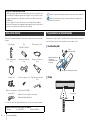
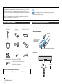
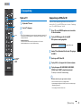
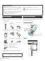
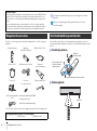
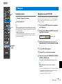
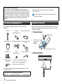
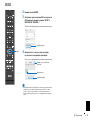
Supplied accessories
Remote control Batteries
(AAA, R03, UM-4) (x2)
Optical cable (1.5 m)
Power cable (2 m)* IntelliBeam microphone
(6 m)
Cardboard microphone
stand
Stands (x2) Screws (For the stands; x2) Subwoofer cable (3 m)
System control cable
(3 m)
• Owner’s Manual CD-ROM
• Quick Reference Guide (this booklet)
• MusicCast Setup Guide
Devices and cables required for connection
• TV • BD/DVD player • HDMI cables (x2)
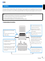
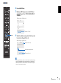
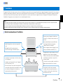
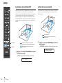
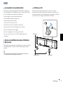
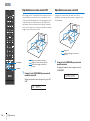
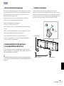
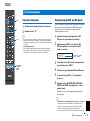
Preparing remote control
Installing the batteries
Operation range
Battery × 2
(AAA, R03, UM-4)
Press down on the arrow
and slide the cover in the
direction in which it
points.
Slide the cover back to close it.
Within 6 m

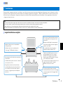
a Installation En 5
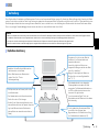
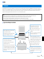
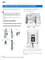
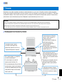
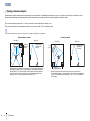
This unit reflects sound beams off of walls and a ceiling to create the surround sound effect. The position of this unit in relation to the listening position, walls, and a ceiling is important
to achieving the desired surround sound effects. Refer to pages 6 to 7 when installing the unit. When installing this unit on a rack behind which there is limited space, for example, it
may be easier to connect external devices to this unit first. This will depend upon the installation location. See page 8 for information regarding the connection of external devices.
a Installation
Notes
• Be sure to install this unit on a large, stable stand where it does not fall subject to vibrations, such as from an earthquake, and where it is out of the reach of children.
• There is a built-in antenna on the top of the unit. Do not install it on a metal rack, and do not stack metal items on top of the unit.
• The unit’s speakers are not magnetically shielded. Do not install hard disk drives or similar devices near the unit.
• Do not stack the unit directly on top of other playback devices, or vice versa. Heat and vibrations may result in damage or malfunction.
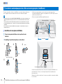
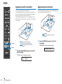
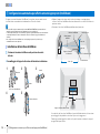
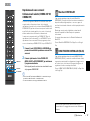
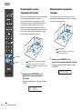
Recommended place for installation
1
Height channel audio is output in a diagonal
direction upward and forward from the unit. As
height channel sound beams are reflected off the
ceiling, sound can be heard from above.
2
Depending upon the rack, table-top stand, or floor
stand used, the stands may not be necessary.
• Install the unit in the center of the left and right
walls.
• This unit can be mounted on a wall. See page 17
in the Owner’s Manual.
• The listening position (such as sofa, etc.) should be
located at the front of the unit.
• The distance between the listening position and the
unit should be more than 1.8 m.
• Set the listening position as far from the back wall as
possible (the optimal listening position is halfway
between the unit and the back wall, or slightly closer
to the back wall).
• To achieve desired surround sound effects, be
sure that obstacles such as furniture may not
obstruct the path of sound beams (p. 6).
• Be sure that the unit installed with at least 5 cm
of empty space above and below it.
• Leaving as much space as possible in a
diagonal direction in front of, and above, the
unit when installing it.
1
• Attach the supplied stands to the unit if it will
be installed on a rack
2
(p. 7).
1 2 3 4

6 En a Installation
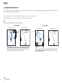
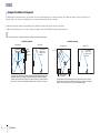
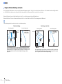
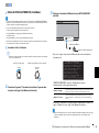
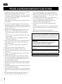
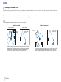
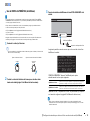
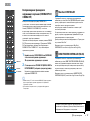
This unit outputs sound beam as shown in the illustrations below. Install this unit where there are no obstacles such as furniture obstructing the path of sound beams. Otherwise, the
desired surround sound effects may not be achieved.
If the unit is installed so that it is parallel to a wall, install it as close to the exact center of the wall as possible.
If the unit is installed in a corner of a room, position it at a 40–50° angle to the adjacent walls.
• See pages 14 to 16 in the Owner’s Manual for additional installation examples.
Example for installing the unit
Objects,
such as
furniture
Viewed from above Viewed from the side
Sound beams
are reflected off
the ceiling
Sound beam output varies depending upon the 3D surround/Surround setting (pages 38
and 39 in the Owner’s Manual) and the channel output setting (page 73 in the Owner’s
Manual). The illustration above shows the path of sound beams when 3D surround is
enabled and “Front” in the Channel Out setting is set to “Beam”.
Parallel installation
40° to 50°
Objects, such as
furniture
Viewed from above Viewed from the side
The illustrations above show the path of sound beams when 3D surround is enabled
(page 38 in the Owner’s Manual) and “Front” in the Channel Out setting is set to “Stereo”.
(page 73 in the Owner’s Manual).
Sound beams
are reflected off
the ceiling
Coner installation
1 2 3 4

a Installation En 7
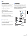
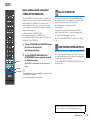
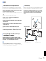
This unit creates surround sound by reflecting projected sound beams off the walls and
the ceiling of your listening room. The surround sound effects produced by this unit
may not be sufficient when this unit is installed in the following locations.
• Rooms with walls inadequate for reflecting sound beams
• Rooms with acoustically absorbent walls and ceiling
• Rooms with measurements outside the following range:
W (3 to 7 m) × H (2 to 3.5 m) × D (3 to 7 m)
• Rooms where objects such as furniture are likely to obstruct the path of sound beams
• Rooms with less than 1.8 m from the listening position to this unit
• Rooms where the listening position is close to the walls
• Rooms where the listening position is not in front of this unit
• Rooms with a complex shape, such as a slanted ceiling (ceiling lights do not obstruct
sound beams)
The My Surround function creates rich surround sound effects in rooms with less than
optimal surround sound conditions. See “Channel Out” (page 73 in the Owner’s
Manual) for more information.
• This unit’s AUTO SETUP (IntelliBeam) can be used to automatically adjust sound beams to achieve the
optimal surround playback environment according to the listening room setup (p. 12).
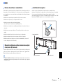
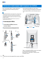
Install the stands (supplied) on the bottom of the unit. Align and insert the protrusion on
the stands into the holes on the rear panel of the unit as shown in the illustration, and
then tighten the screws (supplied) to lock the stands in place. The stands need not be
installed when the unit is mounted on a wall using the optional Wall Mount Bracket
SPM-K30.
Unrecommended listening environments
Enjoying surround effects regardless of conditions (My
Surround)
Installing the stands
Stand (supplied)
Screws (supplied) Stand (supplied)
1 2 3 4

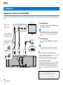
8 En b Connections
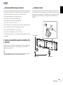
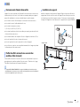
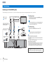
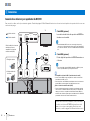
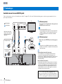
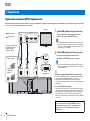
Connecting a TV and BD/DVD player
For the cable connection, follow the procedure below. See pages 23 to 24 in the Owner’s Manual when connecting other playback devices such as a game console.
b Connections
SYSTEM
CONNCETOR
RL
AUX1
AUX2 OPTICAL IR-IN
IN 1
(HDCP2.2)
IN 2
IN 3
IN 4
OUT
(ARC)
HDMI
IR-OUT
UPDATE ONLY
RS-232C
NETWORK
SUBWOOFER
OUT
AC IN
TV
OUT
(ARC)
TV
IN 1
(HDCP2.2)
HDMI INPUT
123
OPTICAL
OUTPUT
HDMI
OUTPUT
BD/DVD player
TV
1. Remove the cap
2. Check the direction of
the plug
Video signals
Audio signals
12
Use an optical cable when
connecting a TV that does not
support Audio Return Channel.
1
HDMI cable (optional)
The digital audio/video signals from the BD/DVD player
are input to this unit.
• This unit supports HDCP version 2.2, a copy protection technology. When
using an HDCP 2.2-compliant playback device, such as a set-top box,
connect it to the unit via the HDMI IN 1 jack.
2
HDMI cable (optional)
Digital video from the BD/DVD player is displayed on the
TV.
• Connect the unit to the HDMI IN jack (one compatible with HDCP 2.2) on
an HDCP 2.2-compliant TV to enjoy playback of 4K video.
Audio Return Channel (ARC) supported TV
• Connect an HDMI cable to the audio return channel supported jack (the jack with
“ARC” indicated) on TV.
• Enable the HDMI control function of this unit to activate the Audio Return
Channel (ARC). See page 77 in the Owner’s Manual.
What is Audio Return Channel (ARC)?
• In order for the unit to play audio from a TV, the TV must usually be connected to
the unit via an audio cable as well as an HDMI cable. If, however, the TV
supports Audio Return Channel (ARC), TV audio signals can be input to the unit
via the HDMI cable that outputs video signals from the unit to the TV.
For a wired network connection, connect one end of the network
cable to the NETWORK jack on the rear panel of the unit and the
other end to a router. For details, see page 52 in the Owner’s
Manual.
1 2 3 4

b Connections En 9
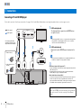
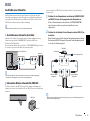
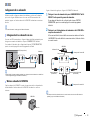
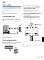
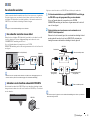
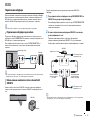
Connecting a subwoofer
A subwoofer can be connected to the unit for use with the unit. There are two ways to
connect a subwoofer to the unit: use a third-party RCA monaural cable, or use the
wireless subwoofer kit SWK-W16 to connect via a wireless connection.
• See page 25 in the Owner’s Manual for more information.
Use a third-party RCA monaural cable to connect the subwoofer to the unit via the
monaural input jack on the subwoofer and the SUBWOOFER OUT jack on the unit.
If a Yamaha subwoofer is connected via the SYSTEM CONNECTOR jack, it turns on
and off when the unit is turned on and off.
• When the unit is connected to the subwoofer via the cable, set the subwoofer output to “Wired” in the setup
menu (page 74 in the Owner’s Manual).
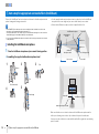
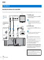
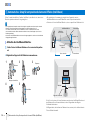
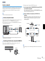
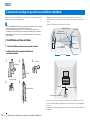
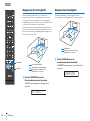
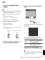
The wireless subwoofer kit SWK-W16 enables wireless connection of a subwoofer to the
unit. Install the SWK-W16 on or near the subwoofer.
Follow the procedure below to connect the SWK-W16 to the subwoofer.
1
Connect subwoofer cable to the SUBWOOFER OUT jack on the
SWK-W16 and the subwoofer’s input jack.
If a Yamaha subwoofer is connected via the SYSTEM CONNECTOR jack, it
turns on and off when the unit is turned on and off.
2
Plug the power cables for the subwoofer and the SWK-W16 into an
AC wall outlet.
When the unit is turned on, a wireless connection between the unit and
SWK-W16 will be established. The status indicator glows green once the
wireless connection is established.
• See “Troubleshooting” (pages 93 and 99 in the Owner’s Manual) if the indicator on the wireless subwoofer
kit does not glow green.
Connecting a subwoofer via cable
Using the wireless subwoofer kit SWK-W16
AUX2 TV OPTICAL
IN 1
(HDCP2.2)
IN 2
IN 3
IN 4
OUT
(ARC)
HDMI
IR-IN IR-OUT
UPDATE ONLY
RS-232C
NETWORK
RL
AUX1
SYSTEM
CONNCETOR
SUBWOOFER
OUT
SYSTEM
CONNECTOR
SUBWOOFER
OUT
INPUT SYSTEM
CONNECTOR
The unit (rear)
Subwoofer
Subwoofer
SWK-W16
SUBWOOFER
OUT
SYSTEM
CONNECTOR
2
2
INPUT
SYSTEM
CONNECTOR
1
1
To an AC wall outlet
Subwoofer cable
(supplied)
To an AC wall outlet
System control cable
(supplied)
SWK-W16
Subwoofer
Status indicator
Rear side
1 2 3 4

10 En b Connections
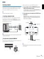
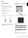
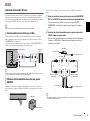
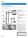
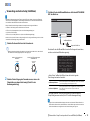
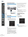
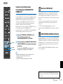
Connecting the power cable
After all the connections are complete, plug in the power cable.
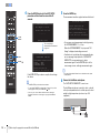
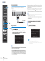
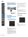
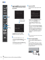
Turning on the unit
1
Press the z key.
When the unit is turned on for the first time after purchase,
the screen below will be displayed on the TV. (“ViewScreen”
is shown in the front panel display.)
• When the screen is not displayed, use the input button on the TV’s remote control
to switch input so that video input from this unit is displayed. When this unit is
connected to the TV as shown on page 8, select “HDMI 1”.
• The language used for menu display (OSD Language) can be selected from the
screen shown above. Use the W/X key to select the language, and follow the
on-screen instructions. The OSD language can also be changed from the setup
menu at any time. Press and hold the SETUP ( ) key until the “OSD Language”
menu is displayed on the TV, and use the S/T key to select the language. Press
the SETUP ( ) key to exit the setup menu.
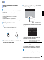
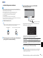
While this screen is displayed, an iOS device (such as an iPhone)
can be used to easily connect the unit to a wireless network. Follow
the procedure below.
If you will not use an iOS device to connect to a wireless network,
press the RETURN ( ) key and proceed to “c Auto setup for
appropriate surround effects (IntelliBeam)”.
• This screen will not be displayed if the unit is connected to a router via its
NETWORK jack (wired connection).
• See page 51 in the Owner’s Manual for wireless network connection methods
other than “Share Wi-Fi Settings”, or for more information regarding wired and
wireless networks.
1
Press the ENTER key.
The screen below is displayed.
• You need iOS device with iOS 7.1 or later.
• Before proceeding, confirm that your iOS device is connected to a wireless
router (access point).
SYSTEM
CONNCETOR
RL
AUX1
AUX2 TV OPTICAL
IN
4
OUT
(ARC)
HDMI
IR-IN
SUBWOOFER
OUT
AC IN
The unit (rear)
To an AC wall outlet
Share Wi-Fi Settings
You can share the wireless
(Wi-Fi) settings of the
network with Sound Projector
using a device with iOS7 or
later.
[ENTER]:Start
[RETURN]:Cancel
[ ]:OSD Language
Connecting the unit to a wireless network
Share Wi-Fi Settings
Make sure your iOS device is
connected to your Wi-Fi
network, and then open the
Wi-Fi settings screen of
your iOS device.
[ENTER]:Confirm
[RETURN]:Cancel
1 2 3 4
RETURN ( )
z
ENTER
SETUP ( )

b Connections En 11
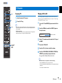
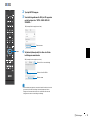
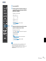
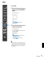
2
Press the ENTER key.
3
Display the Wi-Fi setup screen on the iOS device
and select the unit from “SETUP A NEW AIRPLAY
SPEAKER...”.
4
Select the network (access point) of which you want
to share the settings with the unit.
• You can use this function to connect to a wireless network at any time by selecting
“Share Wi-Fi Settings (iOS)” from the setup menu. However, be aware that if a
different wireless network, or a Bluetooth device, has already been configured,
doing so will erase any previous settings.
iOS (an example of English version)
The name of the unit
Tap here to start setup
The network currently selected
The name of the unit
iOS (an example of English version)
1 2 3 4
ENTER

12 En c Auto setup for appropriate surround effects (IntelliBeam)
First use the “IntelliBeam” function to adjust each channel so that this unit provides the
optimal viewing and listening environment.
• The AUTO SETUP procedure may not be run successfully if this unit is installed in one of the rooms
described in “Unrecommended listening environments” (p. 7).
The My Surround function can be used to enjoy rich surround sound in these types of rooms as well. See
“Channel Out” (page 73 in the Owner’s Manual) for more information.
• Do not connect the IntelliBeam microphone to an extension cable as doing so may result in an inaccurate
sound optimization.
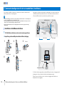
1
Place the IntelliBeam microphone at your normal listening position.
❑ Assembling the supplied cardboard microphone stand
• Use the supplied cardboard microphone stand or a tripod to place the IntelliBeam
microphone at the same height as your ears would be when you are seated.
• Position the IntelliBeam microphone so that it is parallel with the floor.
Make sure that there are no obstacles between the IntelliBeam microphone and the
walls in your listening room as these objects obstruct the path of sound beams.
However, any objects that are in contact with the walls will be regarded as a protruding
part of the walls.
c Auto setup for appropriate surround effects (IntelliBeam)
Installing the IntelliBeam microphone
12
3
5
4
Remove
Fit in
Run through
Place horizontally
Fit in
IntelliBeam microphone
Upper limit
Within 1 m
Center height of
this unit
Cardboard
microphone stand
Within 1 m
Listening position
1.8 m or more
Lower limit
Center line
IntelliBeam microphone
Cardboard microphone stand
1 2 3 4

c Auto setup for appropriate surround effects (IntelliBeam) En 13
• Test tones output during measurement are loud. Perform AUTO SETUP when no children are around and
there is no possibility of their entering the listening room, as their hearing may be impaired.
• If there are curtains in your listening room, we recommend following the procedure below.
1. Open the curtains to improve sound reflection.
2. Run “Beam optimize only” (page 33 in the Owner’s Manual).
3. Close the curtains.
4. Run “Sound optimize only” (page 33 in the Owner’s Manual).
• Make sure that your listening room is as quiet as possible. For accurate measurement, turn off air
conditioner or other devices that make noises.
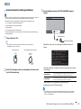
1
Turn the unit and your TV on.
• When a subwoofer is connected to the unit, turn on the subwoofer, and set the volume and crossover
frequency as shown below.
2
Switch TV input to display video input from this unit (page 28 in the
Owner’s Manual).
3
Connect the IntelliBeam microphone to the INTELLIBEAM MIC jack
of the unit.
The screen below is displayed after connecting IntelliBeam microphone to the
unit.
“AUTO SETUP” in the “IntelliBeam” menu can automatically adjust the
following two settings.
“Beam optimize only” or “Sound optimize only” can be measured separately in
the setup menu (page 33 in the Owner’s Manual).
• Follow the instructions below and then leave the room. If you remain in the room, you may obstruct
the beam, or the microphone may pickup any sounds you make, possibly resulting in improper
measurement.
Using AUTO SETUP (IntelliBeam)
VOLUME
MIN MAX MIN
MAX
CROSSOVER
HIGH CUT
Set the volume to half Set the crossover frequency to maximum
Beam optimize only
This feature optimizes the beam angle so that the parameter best
matches your listening environment.
Sound optimize only
This feature optimizes sound quality for each channel by
measuring the acoustic characteristics of the listening
environment.
INTELLIBEAM MIC
INTELLIBEAM MIC
IntelliBeam microphone
Cardboard microphone stand
AUTO SETUP
(PREPARATION & CHECK)
Please connect the MIC.
Please place the MIC at least
1.8m/6ft away from Sound Pro-
jector. The MIC should be set
at ear level when seated.
Measurement takes about 3min.
After [ENTER] is pressed,
please leave the room.
[ENTER]:Start [RETURN]:Cancel
1 2 3 4

14 En c Auto setup for appropriate surround effects (IntelliBeam)
4
Press the ENTER key to start the AUTO SETUP
procedure and then leave the room within 10
seconds.
If the AUTO SETUP procedure is complete, this unit rings
the chimes.
• The AUTO SETUP procedure takes about 3 minutes.
• To cancel the AUTO SETUP procedure after it is started, or if you do not
want to apply the results, press the RETURN ( ) key.
• If an error occurs, an error buzzer sounds and an error message is
displayed. For details on error messages, see page 34 in the Owner’s
Manual.
5
Press the ENTER key.
The measurement results are applied and saved in the unit.
• You can save several measurement results by pressing
the SYSTEM MEMORY 1, 2, or 3 key.
When the SYSTEM MEMORY 1 key is pressed, “M1
Saving” is displayed, and settings are saved.
• If ambient noise is picked up after measurement begins,
an error message is displayed in the “AUTO SETUP
COMPLETE” screen prompting you to begin
measurement again. Press the ENTER key to exit the
error message screen, and begin measurement again.
• See page 45 in the Owner’s Manual for more information on the system
memory function.
6
Remove the IntelliBeam microphone.
The “AUTO SETUP COMPLETE” screen closes.
The IntelliBeam microphone is sensitive to heat, so should
not be placed anywhere where it could be exposed to direct
sunlight or high temperatures (such as on top of AV
equipment).
SHOW RESULT
MEASUREMENT COMPLETE.
ENVIRONMENT CHECK:Success
FRONT :Beam
SURROUND :Beam
SUBWOOFER:Wired
[ENTER]:Save set-up.
[RETURN]:Do not save set-up.
AUTO SETUP START
Will begin in 10 sec.
Please leave the room.
----------
[RETURN]:Cancel
The screen changes
automatically as measurement
progresses.
AUTO SETUP COMPLETE
Please remove the MIC
from Sound Projector
and the listening position.
Press [SYSTEM MEMORY] key
to save set-up in the memory.
INTELLIBEAM MIC
INTELLIBEAM MIC
1 2 3 4
RETURN ( )
SYSTEM
MEMORY
ENTER

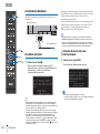
d Playback En 15
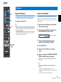
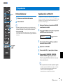
Enjoying TV
1
Select the desired TV channel.
2
Press the TV key.
• When audio is output from the TV speaker, set TV’s audio output to an option
(output to the unit) other than TV. Refor to documentation supplied with TV for
more information.
• HDMI control function
You can use the TV remote control to operate this unit if your TV supports the
HDMI control function. See page 35 in the Owner’s Manual.
Playing a DVD or BD
The following explains the playback procedure when this unit is
connected to the TV and BD/DVD player as shown in “Connecting
a TV and BD/DVD player” (p. 8).
1
Turn on the TV and BD/DVD player connected to this
unit.
2
Press the HDMI key to select the BD/DVD player as
the input source.
3
Use the TV’s remote control to switch the TV’s input
to HDMI 1.
4
Play back a DVD or BD.
5
Press the VOL (+/-) key to adjust the volume.
6
Press the 3D SURROUND, SURROUND, STEREO, or
TARGET key according to your preferences.
See page 38 in the Owner’s Manual for details.
When this unit does not play back, check the following
• The unit and BD/DVD player are connected correctly.
• The audio output settings of the BD/DVD player is set to digital sound output
(bitstream).
• The TV’s input is switched to this unit.
d Playback
HDMI1
Input source name
TV
HDMI1
VOL (+/-)
3D SURROUND
SURROUND
STEREO
TARGET
1 2 3 4

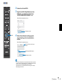
16 En d Playback
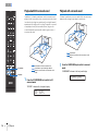
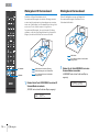
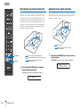
Playback with 3D surround sound
In addition to 5-channel sound beams used for surround sound
playback in the horizontal direction, surround sound can be heard
from above by directing two sound beams (from height channels)
upward and reflecting them off the ceiling. Compared to surround
sound playback in only the horizontal direction, this gives the
sound field (spatial expression with sounds) a greater sense of
immersion and reality.
1
Press the 3D SURROUND key to switch to 3D
surround mode.
“3D SUR.” is shown in the front panel display.
Playback with surround sound
5-channel sound beams create a sound field for surround sound
playback without using height channel sound beams.
1
Press the SURROUND key to switch to surround
mode.
“SURROUND” is shown in the front panel display.
Sound beams in the horizontal direction
Sound beams output from height channels
Channels created from the front and rear sound
beams
3D SUR.
Sound beams
Channels created from the front and rear sound
beams
SURROUND
1 2 3 4
3D SURROUND
SURROUND

d Playback En 17
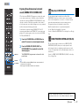
Enjoying three-dimensional surround
sound (CINEMA DSP 3D/CINEMA DSP)
Select the desired CINEMA DSP program according to the audio
source and your preferences. Yamaha’s exclusive sound field
reproduction technology (CINEMA DSP 3D/CINEMA DSP) easily
reproduces realistic sound fields comparable to those found in
movie theaters and concert halls, allowing users to enjoy a natural
and three-dimensional listening environment.
Sound fields are reproduced using CINEMA DSP 3D for 3D
surround sound playback, and CINEMA DSP for surround sound
playback. The same programs can be selected for both CINEMA
DSP 3D and CINEMA DSP.
1
Press the 3D SURROUND or SURROUND key to
enable 3D surround or surround playback mode.
2
Press the CINEMA DSP (MOVIE, MUSIC, or
ENTERTAINMENT) key repeatedly to select the
desired program.
The CINEMA DSP program name is shown in the front
panel display.
• Press the OFF key to disable CINEMA DSP. Audio content is played in 3D
surround mode or surround mode.
• Refer to page 39 in the Owner’s Manual for more information.
MusicCast CONTROLLER
The free dedicated app for mobile devices, MusicCast
CONTROLLER, allows you to listen to music stored on mobile
devices such smartphones, or on servers, or to listen to Internet
radio stations and many kinds of major streaming services.
This app also allows you to distribute content to other
MusicCast-enabled devices for synchronized playback.
See the “MusicCast Setup Guide” for details.
Search for “MusicCast CONTROLLER” on the App Store or Google
Play.
HOME THEATER CONTROLLER (WLAN)
The free dedicated app for mobile devices, HOME THEATER
CONTROLLER (WLAN), allows you to easily operate the unit,
performing such tasks as configuring sound beams on a visual
screen, selecting an input source, and adjusting the volume on a
mobile device.
Search for “HOME THEATER CONTROLLER (WLAN)” on the App
Store or Google Play.
The unit is equipped with a number of other functions not
described in this booklet. See the Owner’s Manual for details.
1 2 3 4
CINEMA DSP
3D SURROUND
SURROUND

2 Fr
1 Pour utiliser l’appareil au mieux de ses possibilités, lisez attentivement ce mode d’emploi.
Conservez-le soigneusement pour référence.
2 Installez cet ensemble audio dans un endroit bien aéré, frais, sec et propre - veillez à ce qu’il soit à
l’abri de la lumière directe du soleil, des sources de chaleur, des vibrations, des poussières, de
l’humidité et/ou du froid. Pour une ventilation correcte, ménagez l’espace minimum suivant.
Au-dessus : 5 cm, À l’arrière : 5 cm, Sur les côtés : 5 cm
3 Placez l’appareil loin des équipements, moteurs et transformateurs électriques, pour éviter les
ronflements parasites.
4 N’exposez pas l’appareil à des variations brutales de température, ne le placez pas dans un
environnement très humide (par exemple dans une pièce contenant un humidificateur) car cela peut
entraîner la condensation d’humidité à l’intérieur de l’appareil qui elle-même peut être responsable
de décharge électrique, d’incendie, de dommage à l’appareil ou de blessure corporelle.
5 Evitez d’installer l’appareil dans un endroit où des objets peuvent tomber, ainsi que là où l’appareil
pourrait être exposé à des éclaboussures ou des gouttes d’eau. Sur le dessus de l’appareil, ne placez
pas :
– d’autres appareils qui peuvent endommager la surface de l’appareil ou provoquer sa
décoloration.
– des objets se consumant (par exemple, une bougie) qui peuvent être responsables d’incendie, de
dommage à l’appareil ou de blessure corporelle.
– des récipients contenant des liquides qui peuvent être à l’origine de décharge électrique ou de
dommage à l’appareil.
6 Ne couvrez pas l’appareil d’un journal, d’une nappe, d’un rideau, etc. car cela empêcherait
l’évacuation de la chaleur. Toute augmentation de la température intérieure de l’appareil peut être
responsable d’incendie, de dommage à l’appareil ou de blessure corporelle.
7 Ne branchez pas la fiche du câble d’alimentation de l’appareil sur une prise secteur aussi longtemps
que tous les raccordements n’ont pas été effectués.
8 Ne pas faire fonctionner l’appareil à l’envers. Il risquerait de chauffer et d’être endommagé.
9 N’exercez aucune force excessive sur les commutateurs, les boutons et les cordons.
10 Pour débrancher la fiche du cordon d’alimentation au niveau de la prise secteur, saisissez la fiche et
ne tirez pas sur le cordon.
11 Ne nettoyez pas l’appareil au moyen d’un solvant chimique, ce qui pourrait endommager la
finition. Utilisez un chiffon sec et propre.
12 N’alimentez l’appareil qu’à partir de la tension prescrite. Alimenter l’appareil sous une tension
plus élevée est dangereux et peut être responsable d’incendie, de dommage à l’appareil ou de
blessure corporelle. Yamaha ne saurait être tenue responsable des dommages résultant de
l’alimentation de l’appareil sous une tension autre que celle prescrite.
13 Veillez à brancher l'instrument sur une prise appropriée raccordée à la terre. Toute installation non
correctement mise à la terre risque d'entraîner un choc électrique, l'endommagement de l'appareil
ou même un incendie.
14 Pour empêcher tout dommage causé par les éclairs, déconnectez le câble d’alimentation et toute
antenne extérieure de la prise murale pendant un orage.
15 Ne tentez pas de modifier ni de réparer l’appareil. Consultez le service Yamaha compétent pour
toute réparation qui serait requise. Le coffret de l’appareil ne doit jamais être ouvert, quelle que soit
la raison.
16 Si vous envisagez de ne pas vous servir de l’appareil pendant une longue période (par exemple,
pendant les vacances), débranchez la fiche du câble d’alimentation au niveau de la prise secteur.
17 Veuillez vous reporter à la section « Guide de dépannage » du mode d’emploi sur le CD-ROM
concernant les erreurs de fonctionnement courantes avant d’en conclure que l’appareil est
défectueux.
18 Avant de déplacer l’appareil, appuyez sur A pour placer l’appareil en veille puis débranchez la
fiche du câble d’alimentation au niveau de la prise secteur.
19 La condensation se forme lorsque la température ambiante change brusquement. En ce cas,
débranchez la fiche du câble d’alimentation et laissez l’appareil reposer.
20 La température de l’appareil peut augmenter en raison d’une utilisation prolongée. En ce cas,
coupez l’alimentation de l’appareil et laissez-le au repos pour qu’il refroidisse.
21 Installez cet appareil à proximité de la prise secteur et à un emplacement où la fiche du câble
d’alimentation est facilement accessible.
22 Les piles ne doivent pas être exposées à une chaleur extrême, par exemple au soleil, à une flamme,
etc. Lors de la mise au rebut des piles, suivez vos réglementations locales.
23 Tenez ce produit hors de la portée des enfants afin d’éviter qu’ils n’avalent les petites pièces.
24 Une pression excessive du son par les écouteurs et le casque d’écoute peut entraîner la perte de
l’ouïe.
ATTENTION : VEUILLEZ LIRE CE QUI SUIT AVANT D’UTILISER L’APPAREIL.
Cet appareil n’est pas déconnecté du secteur tant qu’il reste branché à la prise de courant, même
si l’appareil en soi est éteint par la touche A. Il se trouve alors « en veille ». En mode veille,
l’appareil consomme une très faible quantité de courant.
AVERTISSEMENT
POUR RÉDUIRE LES RISQUES D’INCENDIE OU DE DÉCHARGE ÉLECTRIQUE,
N’EXPOSEZ PAS CET APPAREIL À LA PLUIE OU À L’HUMIDITÉ.
Ne pas utiliser cet appareil à moins de 22 cm de personnes ayant un stimulateur cardiaque ou un
défibrillateur.
Les ondes radio peuvent avoir une incidence sur les équipements électroniques médicaux.
N’utilisez pas cet appareil à proximité d’équipements médicaux ou à l’intérieur d’institutions
médicales.
La plaque signalétique pour le SWK-W16 se trouve au bas de l’appareil.
Français

Fr 3
■ Remarques à propos des télécommandes et piles
• Ne renversez aucun liquide sur le boîtier de télécommande.
• Ne laissez pas tomber le boîtier de télécommande.
• Ne laissez pas et ne rangez pas le boîtier de télécommande dans les endroits suivants:
– très humides, par exemple près d’un bain
– très chauds, par exemple près d’un poêle ou d’un appareil de chauffage
– exposés à des températures très basses
–poussiéreux
• Installez la pile en respectant les repères de polarité (+ et –).
• Si les piles sont vieilles, la portée de la télécommande risque de diminuer considérablement. Le cas
échéant, remplacez les piles le plus rapidement possible par deux piles neuves.
• Si la pile est plate, retirez-la immédiatement de la télécommande pour éviter tout risque d'explosion
ou de fuite d'acide.
• Si vous remarquez une fuite au niveau des piles, mettez-les immédiatement au rebut en prenant soin
de ne pas toucher le produit qui a fui. Si le produit qui a fui entre en contact avec votre peau ou vos
yeux ou votre bouche, rincez immédiatement et consultez un médecin. Nettoyez soigneusement le
logement des piles avant de mettre en place des piles neuves.
• N’utilisez pas à la fois des piles neuves et des piles usagées. Cela risque de réduire la durée de vie des
nouvelles piles ou d'entraîner une fuite des piles usagées.
• N’utilisez pas non plus des piles de deux types différents (par exemple, des piles alcalines et des piles
au manganèse). Il y a risque d’explosion en cas d’erreur dans la mise en place des piles. Les
caractéristiques des piles peuvent être différentes même si elles semblent identiques.
• Avant de mettre la nouvelle pile en place, essuyez soigneusement le compartiment.
• Conservez les piles hors de portée des enfants. SI une pile est avalée accidentellement, contactez
immédiatement votre médecin.
• Si vous prévoyez de ne pas utiliser la télécommande pendant une période prolongée, retirez les piles
de la télécommande.
• N’essayez pas de charger ou de démonter les piles fournies.
Pour afficher le Mode d’emploi, cliquez sur « Français » sur l’écran qui s’affiche automatiquement
lorsque vous insérez le CD-ROM dans votre PC ou cliquez sur le nom du modèle si l’écran pour
sélectionner les modèles s’affiche, ensuite, cliquez sur « Français » sur l’écran suivant. Ensuite, suivez
les instructions à l’écran.
Si l’écran ne s’affiche pas automatiquement, ouvrez le fichier « index.html » sur le CD-ROM.
Vous pouvez télécharger le Mode d’emploi inclus sur le CD-ROM sur le site Web suivant:
URL : http://download.yamaha.com/
Information concernant la collecte et le traitement des piles usagées et
des déchets d’équipements électriques et électroniques
Les symboles sur les produits, l’emballage et/ou les documents joints signifient que les
produits électriques ou électroniques usagés ainsi que les piles ne doivent pas être
mélangés avec les déchets domestiques habituels.
Pour un traitement, une récupération et un recyclage appropriés des déchets
d’équipements électriques et électroniques et des piles usagées, veuillez les déposer aux
points de collecte prévus à cet effet, conformément à la réglementation nationale et aux
Directives 2002/96/EC et 2006/66/EC.
En vous débarrassant correctement des déchets d’équipements électriques et
électroniques et des piles usagées, vous contribuerez à la sauvegarde de précieuses
ressources et à la prévention de potentiels effets négatifs sur la santé humaine qui
pourraient advenir lors d’un traitement inapproprié des déchets.
Pour plus d’informations à propos de la collecte et du recyclage des déchets
d’équipements électriques et électroniques et des piles usagées, veuillez contacter votre
municipalité, votre service de traitement des déchets ou le point de vente où vous avez
acheté les produits.
[Information sur le traitement dans d’autres pays en dehors de l’Union
Européenne]
Ces symboles sont seulement valables dans l’Union Européenne. Si vous souhaitez vous
débarrasser de déchets d’équipements électriques et électroniques ou de piles usagées,
veuillez contacter les autorités locales ou votre fournisseur et demander la méthode de
traitement appropriée.
Note pour le symbole « pile » (les deux symboles du bas) :
Ce symbole peut être utilisé en combinaison avec un symbole chimique. Dans ce cas il
respecte les exigences établies par la Directive pour le produit chimique en question.

4 Fr Accessoires fournis
Avant le raccordement de l’appareil, vérifiez que vous disposez de tous les éléments
suivants.
* La forme de la fiche du câble d’alimentation varie selon le lieu d’achat de l’appareil.
Avant de mettre les piles en place ou d’utiliser la télécommande, assurez-vous de lire
les précautions au sujet de la télécommande et des piles dans ce livret.
À propos de ce Guide de référence rapide
Ce Guide de référence rapide fournit des instructions pour raccorder un téléviseur et
un lecteur BD/DVD à l’appareil, appliquer des réglages et lire des contenus. Pour de
plus amples informations sur les opérations, reportez-vous au Mode d’emploi sur le
CD-ROM fourni.
Lisez les consignes de sécurité décrites dans ce livret avant d’utiliser l’appareil.
Consultez la documentation accompagnant chaque appareil externe pour obtenir des
instructions concernant leur fonctionnement ou leur réglage.
• signale des explications supplémentaires permettant une meilleure utilisation.
• signale les précautions à prendre concernant l’utilisation de l’appareil et les
limites de ses fonctions.
Accessoires fournis
Télécommande Piles
(AAA, R03, UM-4) (x2)
Câble optique (1,5 m)
Câble d’alimentation
(2 m)*
Microphone IntelliBeam
(6 m)
Pied du microphone en
carton
Supports (x2) Vis (Pour les supports ; x2) Câble du caisson de basse
(3 m)
Câble de commande du
système (3 m)
• Mode d’emploi CD-ROM
• Guide de référence rapide (ce document)
• Guide d’installation MusicCast
Appareils et câbles nécessaires pour le raccordement
• Téléviseur • Lecteur BD/DVD • Câbles HDMI (x2)
Préparation de la télécommande
Insertion des piles
Portée
2 piles
(AAA, R03, UM-4)
Appuyez sur la flèche et
faites glisser le
couvercle dans le sens
de la flèche.
Faites glisser le couvercle pour le fermer.
Dans les 6 m
Sidan laddas...
Sidan laddas...
Sidan laddas...
Sidan laddas...
Sidan laddas...
Sidan laddas...
Sidan laddas...
Sidan laddas...
Sidan laddas...
Sidan laddas...
Sidan laddas...
Sidan laddas...
Sidan laddas...
Sidan laddas...
Sidan laddas...
Sidan laddas...
Sidan laddas...
Sidan laddas...
Sidan laddas...
Sidan laddas...
Sidan laddas...
Sidan laddas...
Sidan laddas...
Sidan laddas...
Sidan laddas...
Sidan laddas...
Sidan laddas...
Sidan laddas...
Sidan laddas...
Sidan laddas...
Sidan laddas...
Sidan laddas...
Sidan laddas...
Sidan laddas...
Sidan laddas...
Sidan laddas...
Sidan laddas...
Sidan laddas...
Sidan laddas...
Sidan laddas...
Sidan laddas...
Sidan laddas...
Sidan laddas...
Sidan laddas...
Sidan laddas...
Sidan laddas...
Sidan laddas...
Sidan laddas...
Sidan laddas...
Sidan laddas...
Sidan laddas...
Sidan laddas...
Sidan laddas...
Sidan laddas...
Sidan laddas...
Sidan laddas...
Sidan laddas...
Sidan laddas...
Sidan laddas...
Sidan laddas...
Sidan laddas...
Sidan laddas...
Sidan laddas...
Sidan laddas...
Sidan laddas...
Sidan laddas...
Sidan laddas...
Sidan laddas...
Sidan laddas...
Sidan laddas...
Sidan laddas...
Sidan laddas...
Sidan laddas...
Sidan laddas...
Sidan laddas...
Sidan laddas...
Sidan laddas...
Sidan laddas...
Sidan laddas...
Sidan laddas...
Sidan laddas...
Sidan laddas...
Sidan laddas...
Sidan laddas...
Sidan laddas...
Sidan laddas...
Sidan laddas...
Sidan laddas...
Sidan laddas...
Sidan laddas...
Sidan laddas...
Sidan laddas...
Sidan laddas...
Sidan laddas...
Sidan laddas...
Sidan laddas...
Sidan laddas...
Sidan laddas...
Sidan laddas...
Sidan laddas...
Sidan laddas...
Sidan laddas...
Sidan laddas...
Sidan laddas...
Sidan laddas...
Sidan laddas...
Sidan laddas...
Sidan laddas...
Sidan laddas...
Sidan laddas...
Sidan laddas...
-
 1
1
-
 2
2
-
 3
3
-
 4
4
-
 5
5
-
 6
6
-
 7
7
-
 8
8
-
 9
9
-
 10
10
-
 11
11
-
 12
12
-
 13
13
-
 14
14
-
 15
15
-
 16
16
-
 17
17
-
 18
18
-
 19
19
-
 20
20
-
 21
21
-
 22
22
-
 23
23
-
 24
24
-
 25
25
-
 26
26
-
 27
27
-
 28
28
-
 29
29
-
 30
30
-
 31
31
-
 32
32
-
 33
33
-
 34
34
-
 35
35
-
 36
36
-
 37
37
-
 38
38
-
 39
39
-
 40
40
-
 41
41
-
 42
42
-
 43
43
-
 44
44
-
 45
45
-
 46
46
-
 47
47
-
 48
48
-
 49
49
-
 50
50
-
 51
51
-
 52
52
-
 53
53
-
 54
54
-
 55
55
-
 56
56
-
 57
57
-
 58
58
-
 59
59
-
 60
60
-
 61
61
-
 62
62
-
 63
63
-
 64
64
-
 65
65
-
 66
66
-
 67
67
-
 68
68
-
 69
69
-
 70
70
-
 71
71
-
 72
72
-
 73
73
-
 74
74
-
 75
75
-
 76
76
-
 77
77
-
 78
78
-
 79
79
-
 80
80
-
 81
81
-
 82
82
-
 83
83
-
 84
84
-
 85
85
-
 86
86
-
 87
87
-
 88
88
-
 89
89
-
 90
90
-
 91
91
-
 92
92
-
 93
93
-
 94
94
-
 95
95
-
 96
96
-
 97
97
-
 98
98
-
 99
99
-
 100
100
-
 101
101
-
 102
102
-
 103
103
-
 104
104
-
 105
105
-
 106
106
-
 107
107
-
 108
108
-
 109
109
-
 110
110
-
 111
111
-
 112
112
-
 113
113
-
 114
114
-
 115
115
-
 116
116
-
 117
117
-
 118
118
-
 119
119
-
 120
120
-
 121
121
-
 122
122
-
 123
123
-
 124
124
-
 125
125
-
 126
126
-
 127
127
-
 128
128
-
 129
129
-
 130
130
-
 131
131


på andra språk
- italiano: Yamaha YSP-5600 Manuale del proprietario
- español: Yamaha YSP-5600 El manual del propietario
- Deutsch: Yamaha YSP-5600 Bedienungsanleitung
- français: Yamaha YSP-5600 Le manuel du propriétaire
- Türkçe: Yamaha YSP-5600 El kitabı
- English: Yamaha YSP-5600 Owner's manual
- dansk: Yamaha YSP-5600 Brugervejledning
- русский: Yamaha YSP-5600 Инструкция по применению
- suomi: Yamaha YSP-5600 Omistajan opas
- Nederlands: Yamaha YSP-5600 de handleiding
Relaterade papper
-
Yamaha SRT-1500 Bruksanvisning
-
Yamaha YSP-1600 Användarguide
-
Yamaha YSP-5600 Användarmanual
-
Yamaha YSP-2700 Bruksanvisning
-
Yamaha YSP5100BT Användarmanual
-
-
-
Yamaha YSP-2200 Användarmanual
-
-