
(REVISION B)
Xpelair
™
VX100
VX100 (93224AW) VX100T (93225AW)
VX120
(93228AW) VX120T (93229AW)
VX150
(93226AW) VX150T (93227AW)
User guide
Bruksanvisning
English Svensk
VX Manual_Latest.indd 1-2 04/02/2016 13:52:40

02 03
B
A
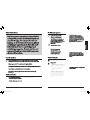
100/120/150mm
150mm
150mm
98mm
15mm 75mm
C
E
D
VX100
170mm
170mm
118mm
15mm 75mm
210mm
210mm
148mm
15mm 75mm
90°
VX120
VX150
VX Manual_Latest.indd 3-4 04/02/2016 13:52:41

04 05
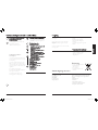
L
N
T
VX100/VX120/VX150
VX100T/VX120T/VX150T
VX100T/VX120T/VX150T
VX100T/VX120T/VX150T
N
L
N
T
L
H
+
-
I
30 SEC 30 MIN
J
5mm
-
+
VX100/VX120/VX150
F
G
VX Manual_Latest.indd 5-6 04/02/2016 13:52:41

This appliance can be used by children aged from 8
years and above and persons with reduced physical,
sensory capabilities or lack of experience and knowledge
if they have been given supervision or instruction
concerning the use of the appliance in a safe way and
understand the hazards involved. Children shall not play
with the appliance. Cleaning and maintenance of the
appliance shall not be made by children.
Check that the electrical rating shown on each fan matches the mains supply.
All installations must be supervised by a qualified electrician. Installations and
wiring must conform to current local regulations.
Do read the entire instruction leaflet before commencing installation.
Do make sure the mains supply is switched o before attempting to make
electrical connections or carry out any maintenance or cleaning.
The appliance is double insulated and does not require an earth connection.
This appliance is intended for connection to fixed wiring.
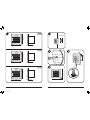
Locate it as high as possible. At least 110mm
from the edges of the mounting surface to
the centre of the hole. As far away as possible
from and opposite to the main source of air
replacement to ensure airflow across the
room (e.g. opposite the internal doorway).
Near the source of steam or odours.
Not where ambient temperatures are likely
to exceed 50°C. If installed in a kitchen,
fans must not be mounted immediately
above a cooker hob, or eye level grill.
If installing in a room containing a fuel
burning device which has a non-balanced
Always check the appropriate size of
space before installing the fan.
Wall Mounting
• Aø100/120/150mmpreparedhole.
• AnappopriateexternalWallGrilleandwall
sleeveduct.
flue, it is the installer’s responsibility to
ensure that there is enough replacement air
to prevent fumes being drawn down the flue
when the fan is operating up to maximum
extract. Refer to Building Regulations for
specific requirements. Exhaust air must not
be discharged into a flue used for exhausting
of fumes from appliances supplied with
energy other than electric. Requirements of
all authorities concerned must be observed
for exhaust air discharge and intake flow
rates. Not suitable for use in possible
chemical corrosive atmospheres.
Safety instructions
Before you start
What you will need
General information
Included in the box:
• 3xscrewsand3xwallplugs.
Tools for installation:
• 3mmelectrician’sscrewdriverand
No.1or2Pozidrivscrewdriver.
VX100/120/150
Operatethefanusinganon/offswitch(notsupplied).
A
B
Where to locate the fan
!
!
!
ENGLISH
06 07
VX Manual_Latest.indd 7-8 04/02/2016 13:52:41

Fan installation
Wet Rooms: on/o switch must be
situated so that it cannot be touched
by persons making use of the bath or shower.
A means for disconnection in all poles must be
incorporated in the fixed wiring in accordance
with wiring regulations.
• Ifmetalswitchboxesareused,earthing
regulationsmustbefollowed.
• Thecross-sectionalareaofthesupplycord
usedshouldberangedbetween1-1.5mm².
• VX100/VX120/VX150–2core,
VX100T/VX120T/VX150T–3core.
• VX100T/VX120T/VX150T.Awallor
ceilingon/oswitch(withindicatorlight)
isrecommended.
Step 1
Checkthattheelectricalratingshownon
thefanmatchesyourmainssupply.
Step 2
Checktherearenoburiedpipesorcables
e.g.electricity,gas,waterbehindtheswitch
location (in the wall or above the ceiling).
Ifindoubt,seekprofessionaladvice.
Step 3
Isolatethemainssupply.
Step 4
Installtheisolatingswitchand
on/oswitch(ifrequired).
Step 5
Layinthecablefromtheisolatingswitch
tothefanlocationviatheon/o
switch(ifrequired).
Step 6
Layinthecablefromtheisolating
switch to the point of connection to
themainssupply.
Warning: Do not make any connections
to the electrical supply at this stage.
Step 7
Make all connections within the isolating
switchandtheon/oswitch(ifrequired).
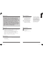
Step 1 – Preparing the fan
for installation
• Undotheelectricalcoverscrewandremove
the electrical cover.
If working above ground floor level, safety
precautions must be observed.
If installing in a ceiling, appropriate
termination ancillaries are required
Step 2 – Mount the fan body
• Ifwallmounting,ensurefanbodyis
orientatedhorizontallysee E.
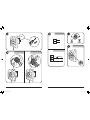
Step 3 – Wire the electrical
connections
• Makesuremainssupplyisisolated.Switchoff
themainselectricalsupplyandremovefuses.
• Pleaseensureyoufollowtherightdiagram
andinstallationtypeforthemodelyouhave
purchasedsee H.
• Usecableclamptosecurecable.
Fan settings
VX100T / VX120T / VX150T
• Toadjusttheover-runsee I. For location of
thetimercontrolsee J.
• Operatethefanusingon/offswitch(not
provided).Whenswitchisoff,fanoperates
forthesettimedelay.
VX100 / VX120 / VX150
• Operatefanusingon/oswitch
(notsupplied).
Finally refit the electrical cover ‘O’ ring seals
(where applicable) and screw in place.
Cleaning
Step 1 – Before cleaning
Isolatethefancompletelyfromthemainssupply.
Step 2 – No water or chemicals
Donotimmersethefaninwaterorotherliquidsto
cleananyotherpartsofthefan.Donotusestrong
detergents,solventsorchemicalcleaners.
Step 3 – Clean front
Wipeitwithadamp,lintfreeclothorwashitwith
warmsoapywater.
C
D
G
F
H
I
Installing switches and cables
!
!
!
!
!
We,RedringXpelairGroupLimited,providea
guaranteeagainstfaultypartsandmanufacture
foraperiodof2yearsfromthedateofpurchase.
Intheunlikelyeventofaproductbreakdown
duringtheguaranteeperiodtheproductshould
bereturnedtotheplaceofpurchaseorto
RedringXpelairGroupLimited.
Exclusions:
• Thisguaranteedoesnotcovercompensation
forthelossoftheproductorconsequential
lossofanykind.
• Damageordefectstotheproductarisingfrom
incorrectinstallationorlackofmaintenance.
• Transportationcosts.
Thisguaranteedoesnotaectyourstatutoryrights.
Contactlocaldistributorfordetails.
www.xpelair.co.uk/international
Guarantee UK Guarantee International
Technical Advice and Service
United Kingdom
Xpelair have a comprehensive range
of services. Please ask for details:
General Enquiries Hotline: +44 (0) 844 372 7761
General Enquiries Faxline: +44 (0) 844 372 7762
Technical Hotline: +44 (0) 844 372 7766
Technical Faxline: +44 (0) 844 372 7767
Sales/Spares Hotline: +44 (0) 844 372 7750
Sales/Spares Faxline: +44 (0) 844 372 7760
Head Oce, UK Sales Oce and Spares
Redring Xpelair Group Ltd, Newcombe House,
Newcombe Way, Orton Southgate,
Peterborough, PE2 6SE England.
www.xpelair.co.uk
International
Technical Advice and Service:
Contact your local Xpelair distributor.
www.xpelair.co.uk/international
ENGLISH
08 09
VX Manual_Latest.indd 9-10 04/02/2016 13:52:41

Den här apparaten kan användas av barn från 8 år
och uppåt och personer med försämrad fysisk och
sensorisk förmåga, eller brist på erfarenhet och
kunskap, om de övervakas eller instrueras gällande
användning av apparaten på ett säkert sätt och är
införstådda med riskerna som föreligger med
användning av apparaten. Barn ska inte leka med
apparaten. Rengöring och underhåll av apparaten
ska inte utföras av barn.
Den här apparaten är avsedd för fast anslutning. Kontrollera att de elektriska
specifikationerna som visas på varje fläkt stämmer överens med nätspänningen.
Inkoppling och service får endast ske i spänningslöst tillstånd.
APPARATEN ÄR DUBBELISOLERAD OCH KRÄVER INGEN JORDNING.
Alla installationer måste utföras av en behörig elektriker.
Installation och kabeldragning måste följa aktuella lokala eller tillämpliga
förordningar.
• Placera den så högt som möjligt.
• Minst 110 mm från kanterna på
monteringsytan till mitten av hålet.
• På så stort avstånd som möjligt från och
mittemot huvudkällan till tilluft för att
garantera ett luftflöde genom rummet (t.ex.
mittemot dörren i rummet eller en
uteluftsventil).
• Nära källan till ånga eller lukt.
• Inte där rumstemperaturen
tenderar att överstiga 50 °C.
• Om fläkten installeras i ett kök
ska den inte monteras direkt
ovanför en spishäll eller ugn.
Tillse att du har rätt fläkt storlek jämfört
med installationsytan innan installation.
Väggmontera
• Om fläkten ska väggmonteras behöver du
Ett förberett hål med en diameter på 100
mm.
• Ett lämpligt externt väggaller och ett
väggenomföringsrör med 100 mm i
diameter
• Om fläkten installeras i ett rum som
innehåller en förbränningsenhet som är
utrustad med en obalanserad rökkanal är det
installatörens ansvar att se till att det finns
tillräckligt med ersättningsluft för att förhindra
att ångor dras ned i rökkanalen när fläkten går
på maximal hastighet. Se
byggnadsföreskrifterna för specifika krav.
• Frånluften måste släppas ut i en kanal
antingen genom vägg eller tak. Krav från alla
relevanta myndigheter måste iakttas gällande
utsläpp av frånluft och flödeshastigheter för
luftintag.
• Ej lämplig för användning i eventuella kemiskt
korrosiva atmosfärer.
Säkerhetsinstruktioner
Innan du installerar
Vad du behöver ha
Allmän information
Vad installatören behöver ha:
• 3 mm skruvmejsel för elektriker
•
Pozidriv-skruvmejsel nr. 1 och 2.
VX100/120/150 fläkten skall installeras med
arbetsbrytare(ej inkluderad)
B
A
Var fläkten ska placeras
!
!
10 11
!
SVENSK
VX Manual_Latest.indd 11-12 04/02/2016 13:52:42
Om fläkten ska takmonteras behöver du:
• Ett förberett hål med en diameter på 100
mm för det externa gallret, optimalt placerat
för att låta kondens rinna undan från den
första kröken på kanalen mot det externa
gallret

12 13
Installera fläkten
En anordning för allpolig frånkoppling skall
finnas i installationen enligt lokala
installationsföreskrifter
• Om kopplingsdosor i metall används måste
regler gällande jordning följas.
• Kabelns area skall vara 1,5 mm².
1. Kontrollera att de elektriska specifikationerna
som visas på typskylten stämmer överens med
din nätspänning.
2. Kontrollera att det inte förekommer några
dolda rör eller kablar, t.ex för elektricitet, gas
eller vatten bakom platsen där brytaren ska sitta
(i väggen eller taket). Om du är tveksam, anlita
en yrkesman.
3. Gör installationen spänningslös.
4. Dra kabeln från arbetsbrytaren till fläkten via
manöverbrytaren (vid behov).
5. Dra kabeln från arbetsbrytaren till
anslutningspunkten för nätspänningen.
Förbereda fläkten för installation
• 1.Ta bort kåpan över elanslutningspunkten
genom att lossa på skruven och lyfta bort
locket.(D)
Vid arbete på stege måste
säkerhetsåtgärder iakttas.
• 2. Om fläkten monteras på vägg säkerställ
att fläkten monteras rakt.
• 3. För försiktigt in fläktröret i
väggkanalen.
• 4. Markera monteringshålens position i
• bottenplattan.
• 5. Ta bort bottenplattan från kanalen.
• 6. Borra skruvhål om det behövs, och sätt
i väggpluggar och skruvar efter behov.
• Montera bottenplattan.
• 7. Mata strömkabeln genom kabelhålet i
• bottenplattan till plinten.
Slutför elanslutningarna.
8. Se till att installationen är
spänningslös.
9. Dra fram kabeln till
kopplingsplinten. Montera fläktens
kablar enligt figur H
10. återmontera locket över
elanslutningen.
11.Anslut kabeln från
arbetsbrytaren till
anslutningspunkten.
Rengöring
C
D
G
F
H
Installera arbetsbrytare och kablar
!
!
!
!
!
1. Före rengöring ska du göra installationen
spänningslös.
2. Rengör kåpan genom att torka av den med en
fuktig, luddfri trasa eller rengör den med varmt
tvålvatten.
3. Sänk inte ned fläkten i vatten eller annan vätska
för att rengöra den.
4. Använd inte starka rengöringsmedel,
lösningar
eller kemiska rengöringsmedel
5. Låt fläkten torka ordentligt före
användning.
6. Förutom rengöring behövs inget annat
underhåll.
Guarantee International
Sverige
Glen DImplex Nordic AB
Linjalvägen 6A
187 66 TÄBY
Tfn 08-471 03 50
www.glendimplex.se
Head Office, UK Sales Office and Spares Redring
Xpelair Group Ltd, Newcombe House, Newcombe
Way, Orton Southgate, Peterborough, PE2 6SE
England.
www.xpelair.co.uk
International
Technical Advice and Service:
Contact your local Xpelair distributor.
www.xpelair.co.uk/international
SVENSK
VX Manual_Latest.indd 13-14 04/02/2016 13:52:42
Om kabeldragning görs till extern
manöverbrytare.
Återvinning
Den här produkten ska inte kastas
med hushållsavfallet.
Lämna in den till en
återvinningsstation.
Kontakta din kommun för mer
information.
Teknisk rådgivning och service
C
o
ntact local distributor for details.
www.xpelair.co.uk/international
www.glendimplex.se

Notes Notes
14 15
VX Manual_Latest.indd 27-28 04/02/2016 13:52:44
-
 1
1
-
 2
2
-
 3
3
-
 4
4
-
 5
5
-
 6
6
-
 7
7
-
 8
8


