Yamaha R-N602 Bruksanvisning
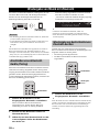
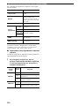
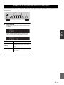
- Kategori
- Mottagare för bilmedia
- Typ
- Bruksanvisning

R-N602
Printed in Malaysia ZS22670-1© 2015 Yamaha Corporation
Network Receiver
Réseau Ampli-Tuner
R-N602
OWNER’S MANUAL
MODE D’EMPLOI
BEDIENUNGSANLEITUNG
BRUKSANVISNING
MANUALE DI ISTRUZIONI
MANUAL DE INSTRUCCIONES
GEBRUIKSAANWIJZING
ИНСТРУКЦИЯ ПО ЭКСПЛУАТАЦИИ
G

i En
English
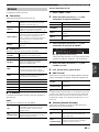
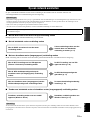
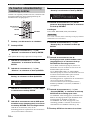
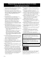
1 To assure the finest performance, please read this manual
carefully. Keep it in a safe place for future reference.
2 Install this sound system in a well ventilated, cool, dry, clean
place – away from direct sunlight, heat sources, vibration,
dust, moisture, and/or cold. For proper ventilation, allow the
following minimum clearances.
Top: 30 cm (11-3/4 in)
Rear: 20 cm (7-7/8 in)
Sides: 20 cm (7-7/8 in)
3 Locate this unit away from other electrical appliances, motors,
or transformers to avoid humming sounds.
4 Do not expose this unit to sudden temperature changes from
cold to hot, and do not locate this unit in an environment with
high humidity (i.e. a room with a humidifier) to prevent
condensation inside this unit, which may cause an electrical
shock, fire, damage to this unit, and/or personal injury.
5 Avoid installing this unit where foreign objects may fall onto
this unit and/or this unit may be exposed to liquid dripping or
splashing. On the top of this unit, do not place:
– Other components, as they may cause damage and/or
discoloration on the surface of this unit.
– Burning objects (i.e. candles), as they may cause fire,
damage to this unit, and/or personal injury.
– Containers with liquid in them, as they may fall and liquid
may cause electrical shock to the user and/or damage to
this unit.
6 Do not cover this unit with a newspaper, tablecloth, curtain,
etc. in order not to obstruct heat radiation. If the temperature
inside this unit rises, it may cause fire, damage to this unit,
and/or personal injury.
7 Do not plug in this unit to a wall outlet until all connections
are complete.
8 Do not operate this unit upside-down. It may overheat,
possibly causing damage.
9 Do not use force on switches, knobs and/or cords.
10 When disconnecting the power cable from the wall outlet,
grasp the plug; do not pull the cable.
11 Do not clean this unit with chemical solvents; this might
damage the finish. Use a clean, dry cloth.
12 Only voltage specified on this unit must be used. Using this
unit with a higher voltage than specified is dangerous and may
cause fire, damage to this unit, and/or personal injury. Yamaha
will not be held responsible for any damage resulting from use
of this unit with a voltage other than specified.
13 To prevent damage by lightning, keep the power cord
disconnected from a wall outlet or the unit during a lightning
storm.
14 Do not attempt to modify or fix this unit. Contact qualified
Yamaha service personnel when any service is needed. The
cabinet should never be opened for any reasons.
15
When not planning to use this unit for long periods of time (i.e.
vacation), disconnect the AC power plug from the wall outlet.
16 Be sure to read the “Troubleshooting” section in the owner’s
manual on common operating errors before concluding that
this unit is faulty.
17 Before moving this unit, press A downward to turn off this
unit and then disconnect the AC power plug from the AC wall
outlet.
18 Condensation will form when the surrounding temperature
changes suddenly. Disconnect the power cable from the
outlet, then leave this unit alone.
19 When using this unit for a long time, this unit may become
warm. Turn the system off, then leave this unit alone for
cooling.
20 Install this unit near the wall outlet and where the AC power
plug can be reached easily.
21 The batteries shall not be exposed to excessive heat such as
sunshine, fire or the like. When you dispose of batteries,
follow your regional regulations.
22 Excessive sound pressure from earphones and headphones
can cause hearing loss.
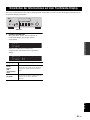
Do not touch the surface having this label. Doing so may cause
burns. The label on the device indicates that the surface to which
the label is attached may become hot during operation.
Caution: Read this before operating your unit.
This unit is not disconnected from the AC power source as long as
it is connected to the wall outlet, even if this unit itself is turned off
by A. This state is called the standby mode. In this state, this unit is
designed to consume a very small quantity of power.
WARNING
TO REDUCE THE RISK OF FIRE OR ELECTRIC SHOCK, DO
NOT EXPOSE THIS UNIT TO RAIN OR MOISTURE.
Do not use this unit within 15 cm (6 inches) of persons with a heart
pacemaker implant or defibrillator implant.

Caution: Read this before operating your unit.
ii En
English
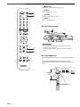
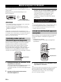
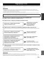
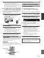
■ Notes on remote controls and batteries
• Do not spill water or other liquids on the remote control.
• Do not drop the remote control.
• Do not leave or store the remote control in the following
conditions:
– places of high humidity, such as near a bath
– places of high temperatures, such as near a heater or stove
– places of extremely low temperatures
– dusty places
• Insert batteries according to the polarity markings (+ and -).
• Change all batteries if you notice the operation range of the
remote control narrows.
• If the batteries run out, immediately remove them from the
remote control to prevent an explosion or acid leak.
• If you find leaking batteries, discard the batteries
immediately, taking care not to touch the leaked material. If
the leaked material comes into contact with your skin or gets
into your eyes or mouth, rinse it away immediately and
consult a doctor. Clean the battery compartment thoroughly
before installing new batteries.
• Do not use old batteries together with new ones. This may
shorten the life of the new batteries or cause old batteries to
leak.
• Do not use different types of batteries (such as alkaline and
manganese batteries) together. Read the packaging carefully
as these different types of batteries may have the same shape
and color.
• Before inserting new batteries, wipe the battery compartment
clean.
• Keep the batteries in a location out of reach of children.
Batteries can be dangerous if a child were to put in his or her
mouth.
• If the batteries grow old, the effective operation range of the
remote control decreases considerably. If this happens,
replace the batteries with new one as soon as possible.
• If you plan not to use the unit for a long period of time,
remove the batteries from the unit. Otherwise, the batteries
will wear out, possibly resulting in a leakage of battery liquid
that may damage the unit.
• Do not throw away batteries with general house waste.
Dispose of them correctly in accordance with your local
regulations.

Caution: Read this before operating your unit.
iii En
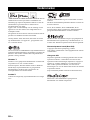
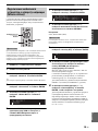
Bluetooth
• Bluetooth is a technology for wireless communication between
devices within an area of about 10 meters (33 ft) employing the
2.4 GHz frequency band, a band which can be used without a
license.
Handling Bluetooth communications
• The 2.4 GHz band used by Bluetooth compatible devices is a
radio band shared by many types of equipment. While
Bluetooth compatible devices use a technology minimizing the
influence of other components using the same radio band, such
influence may reduce the speed or distance of communications
and in some cases interrupt communications.
• The speed of signal transfer and the distance at which
communication is possible differs according to the distance
between the communicating devices, the presence of obstacles,
radio wave conditions and the type of equipment.
• Yamaha does not guarantee all wireless connections between
this unit and devices compatible with Bluetooth function.
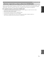
Information for users on collection and
disposal of old equipment and used batteries:
These symbols on the products, packaging, and/or
accompanying documents mean that used electrical
and electronic products and batteries should not be
mixed with general household waste.
For proper treatment, recovery and recycling of old
products and used batteries, please take them to
applicable collection points, in accordance with your
national legislation.
By disposing of these products and batteries
correctly, you will help to save valuable resources
and prevent any potential negative effects on human
health and the environment which could otherwise
arise from inappropriate waste handling.
For more information about collection and recycling
of old products and batteries, please contact your
local municipality, your waste disposal service or the
point of sale where you purchased the items.
For business users in the European Union:
If you wish to discard electrical and electronic
equipment, please contact your dealer or supplier for
further information.
Information on Disposal in other Countries
outside the European Union:
These symbols are only valid in the European Union.
If you wish to discard these items, please contact
your local authorities or dealer and ask for the
correct method of disposal.
Note for the battery symbol (bottom two
symbol examples):
This symbol might be used in combination with a
chemical symbol. In this case it complies with the
requirement set by the EU Battery Directive for the
chemical involved.
Cd

1 En
PREPARATIONINTRODUCTION
BASIC
OPERATION
ADDITIONAL
INFORMATION
ADVANCED
OPERATION
English
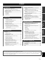
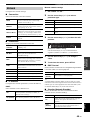
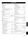
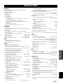
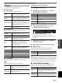
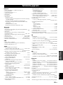
INTRODUCTION
What you can do with this unit ................................. 2
Sources that can be played back on this unit ................. 2
Mastering useful apps (MusicCast CONTROLLER).... 3
Supplied accessories ................................................... 4
Controls and functions ............................................... 5
Front panel ..................................................................... 5
Front display .................................................................. 7
Rear panel ...................................................................... 8
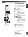
Remote control............................................................... 9
PREPARATION
Connections............................................................... 11
Connecting the speakers .............................................. 12
Connecting the FM and AM antennas ......................... 13
Connecting the network cable ..................................... 14
Preparing a wireless antenna ....................................... 14
Connecting power cable .............................................. 14
Connecting to network ............................................. 15
Sharing the iOS device setting..................................... 16
Using the WPS push button configuration .................. 17
Set the wireless network connection manually............ 18
Connecting a mobile device to the unit directly
(Wireless Direct) ..................................................... 19
Verify the network connection status .......................... 20
BASIC OPERATION
Playback .................................................................... 21
Playing a source........................................................... 21
Using the sleep timer ................................................... 23
Listening to FM/AM radio....................................... 24
FM/AM tuning............................................................. 24
Automatic preset tuning (FM stations only)................ 24
Manual tuning preset ................................................... 25
Recalling a preset station ............................................. 26
Clearing a preset station............................................... 26
Radio Data System tuning ........................................... 27
Playing back music via Bluetooth............................ 28
Connecting a Bluetooth device (pairing) ..................... 28
Playing back Bluetooth device contents ...................... 28
Disconnecting a Bluetooth connection ........................ 29
Playing back music stored on media servers
(PCs/NAS) ............................................................. 30
Setting the media sharing of music files...................... 30
Playback of PC music contents.................................... 31
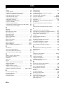
Listening to Internet radio .......................................33
Playing back iPod/iTunes music via a network
(AirPlay).................................................................35
Playback of iPod/iTunes music contents ..................... 35
Playing back music stored on a USB storage
device ......................................................................37
Connecting a USB storage device ............................... 37
Playback of USB storage device contents ................... 37
Playing back iPod music...........................................39
Connecting an iPod...................................................... 39
Playback of iPod content ............................................. 39
Switching information on the front display ............41
Registering the current playback song/station
(Preset function) ....................................................42
Registering to a preset ................................................. 42
Recalling a preset......................................................... 42
ADVANCED OPERATION
Configuring playback settings for different
playback sources (Option menu) .........................43
Option menu items....................................................... 43
Configuring various functions (Setup menu) .........44
Setup menu items......................................................... 44
Network ....................................................................... 45
Bluetooth ..................................................................... 46
Max Volume ................................................................ 47
Initial Volume.............................................................. 47
AutoPowerStdby (Auto Power Standby)..................... 47
ECO Mode................................................................... 47
Configuring the system settings
(ADVANCED SETUP menu)...............................48
ADVANCED SETUP menu items .............................. 48
Changing the speaker impedance setting (SP IMP.) ... 48
Selecting the remote control ID (REMOTE ID).......... 48
Restoring the default settings (INIT)........................... 48
Updating the firmware (UPDATE) ............................. 49
Checking the firmware version (VERSION)............... 49
Updating the unit’s firmware via the network.......50
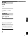
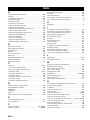
ADDITIONAL INFORMATION
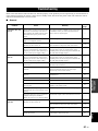
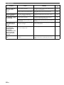
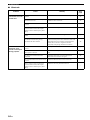
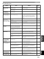
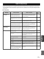
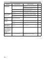
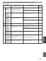
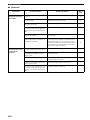
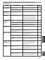
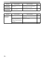
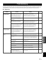
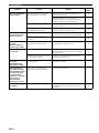
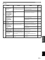
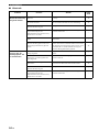
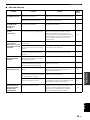
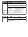
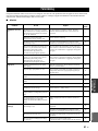
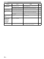
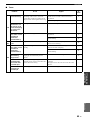
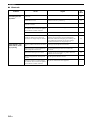
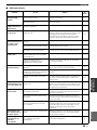
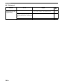
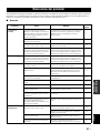
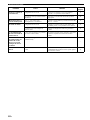
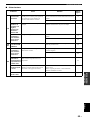
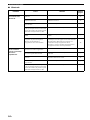
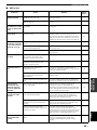
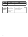
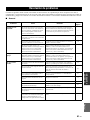
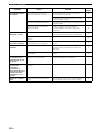
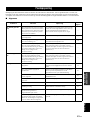
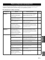
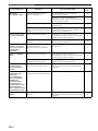
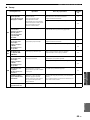
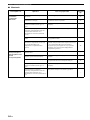
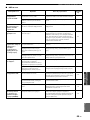
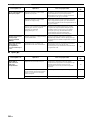
Troubleshooting.........................................................51
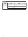
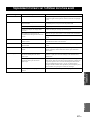
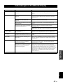
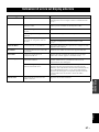
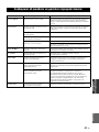
Error indications on the front display.....................57
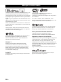
Trademarks ...............................................................58
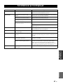
Specifications .............................................................59
Index...........................................................................60
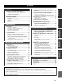
Contents
• “Note” indicates precautions for use of the unit and its feature limitations. y indicates supplementary explanations for better use.
• This manual explains operations using the supplied remote control.
• This manual describes all the “iPod” and “iPhone” as the “iPod”. “iPod” refers to “iPod” and “iPhone”, unless otherwise specified.
• In this manual, iOS and Android mobile devices are collectively referred to as “mobile devices”. The specific type of mobile
device is noted in explanations as needed.

2 En
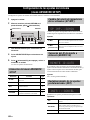
INTRODUCTION
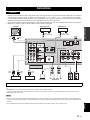
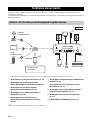
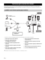
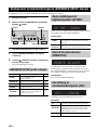
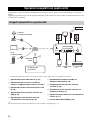
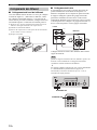
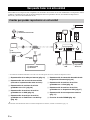
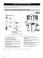
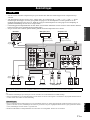
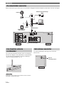
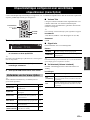
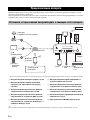
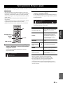
This unit is a network receiver compatible with a network source such as a media server and mobile device.
It supports playback from not only analog sources such as a CD player but also Bluetooth devices and network streaming
services.
*
You need a commercially available wireless router (access point) when you use a mobile device.
1 Play back the Internet radio (p. 33)
2 Play back the streaming service
(see the supplement for each service.)
3 Play back music files stored on your PC (p. 30)
4 Play back music files stored on your NAS
(p. 30)
5 Play back music files stored on your iPod/
iTunes with AirPlay (p. 35)
6 Play back audio content from Bluetooth
devices (p. 28)
7 Play back music files stored on your iPod
(p. 39)
8 Play back music files stored on your USB
device (p. 37)
9 Play back your external component (p. 11)
0 Listening to FM/AM radio (p. 24)
y
For details on connecting the external devices, see “Connections” (p. 11).
What you can do with this unit
Sources that can be played back on this unit
FM/AMFM/AM
VOLUME
PURE DIRECT
RETURN
CONNECT
PUSH - ENTER
TUNINGPRESET
BAND
MEMORY CLEAR
BASSINPUT
5V
1A
BALANCE
LR
TREBLE
LOUDNESS
FLAT
-30dB
DIMMER
DISPLAY
SELECT
PHONES
SPEAKERS
AB
MODE
This unit
1 Internet
2 Streaming service
Modem
Router*
3 PC
5 AirPlay (iTunes)
4 NAS
7 iPod
0
5 AirPlay (iPod)
6 Bluetooth
8 USB
device
9 CD player etc.
Mobile
device

What you can do with this unit
3 En
INTRODUCTION
English
You can operate and program the unit, or play streaming services via this unit, by installing the free dedicated MusicCast
CONTROLLER app on a mobile device. For details, search for “MusicCast CONTROLLER” on the App Store or
Google Play.
■ MusicCast CONTROLLER capabilities
• Basic operations of the unit (turn on/standby, adjust volume and select input)
• Play songs stored on computers (servers)
• Select an Internet radio station
• Play music stored on mobile devices
• Play music on streaming service
• Distribute and receive audio between the unit and other Yamaha MusicCast supported devices
See MusicCast Setup Guide for details.
Mastering useful apps (MusicCast CONTROLLER)

4 En
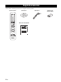
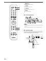
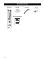
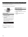
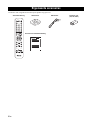
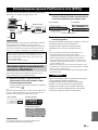
Check that the following accessories are supplied with the product.
Supplied accessories
LINE 1
OPT 1 OPT 2 CD
COAX 1 COAX 2
BLUETOOTH
NET USB
LINE 2 LINE 3
TUNER
PRESET
TUNING
BAND
MEMORY
SETUP
HOME
MUTENOW PLAYING
VOLUME
RETURN
ENTER
REPEAT
SHUFFLE
SLEEP
PHONO
B
A
SPEAKERS
OPTION
Remote control
FM antennaAM antenna
Batteries (x2)
(AA, R6, UM-3)
MusicCast Setup Guide

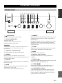
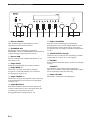
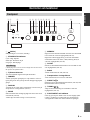
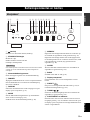
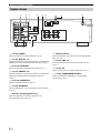
Controls and functions
5 En
INTRODUCTION
English
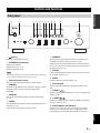
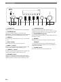
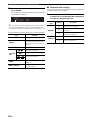
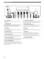
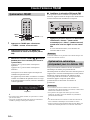
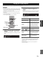
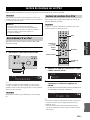
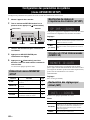
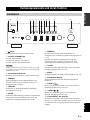
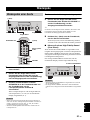
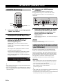
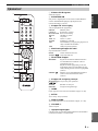
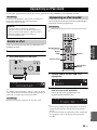
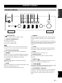
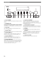
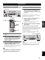
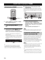
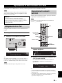
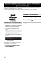
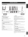
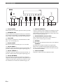
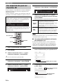
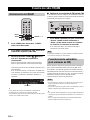
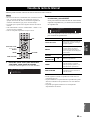
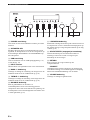
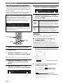
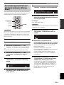
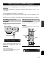
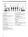
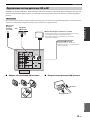
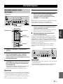
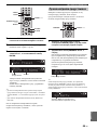
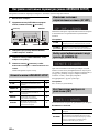
1 A (power)
Turns on/off (standby) the unit.
2 STANDBY/ON indicator
Lights up as follows:
Brightly lit: Power is on
Dimly lit: Standby mode
In standby mode, this unit consumes a small amount of power to
receive infrared signals from the remote control.
3 Remote control sensor
Receives infrared signals from the remote control.
4 DIMMER
Changes the brightness level of the front display. Choose
brightness from 5 levels by pressing this button
repeatedly.
5 DISPLAY
Selects the information displayed on the front display
(p. 41).
6 MODE
Sets the FM band reception mode to automatic stereo or
monaural (p. 24).
Switches the iPod operation modes (p. 40).
7 MEMORY
Registers the current FM/AM station as a preset when
TUNER is selected as the input source (p. 25).
Registers the current playback song or streaming station
as a preset when NET, USB (except iPod) are selected as
the input source (p. 42).
8 CLEAR
Clears a FM/AM preset station when TUNER is selected
as the input source (p. 26).
9 BAND
Switches between FM and AM (p. 24).
0 Front display
Shows information about the operational status of this
unit.
A PRESET j / i
Recalls a preset FM/AM station (p. 26) or song/streaming
station (p. 42).
B TUNING jj / ii
Selects the tuning frequency when TUNER is selected as
the input source (p. 24).
C PURE DIRECT and indicator
Allows you to listen to a source in the purest possible
sound (p. 21). The indicator above it lights up and the
front display turns off when this function is turned on.
Controls and functions
Front panel
VOLUME
PURE DIRECT
RETURN
CONNECT
PUSH - ENTER
TUNINGPRESET
BAND
MEMORY CLEAR
BASSINPUT
5V
1A
BALANCE
LR
TREBLE
LOUDNESS
FLAT
-30dB
DIMMER MODE
DISPLAY
SELECT
PHONES
SPEAKERS
AB
12 3 4 5 6 7 8 9: B CA
Note

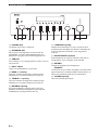
Controls and functions
6 En
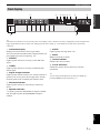
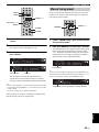
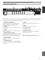
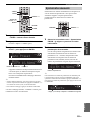
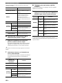
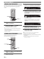
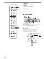
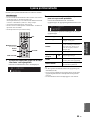
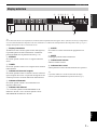
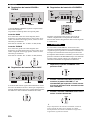
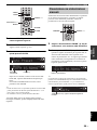
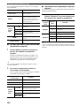
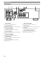
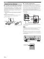
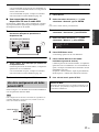
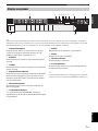
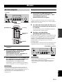
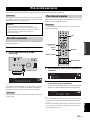
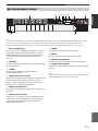
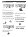
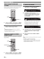
D PHONES jack
Outputs audio to your headphones for private listening.
E SPEAKERS A/B
Turns on or off the speaker set connected to the
SPEAKERS A and/or SPEAKERS B terminals on the rear
panel each time the corresponding button is pressed.
F USB jack
For connecting a USB storage device (p. 37) or an iPod
(p. 39).
G INPUT selector
Selects the input source you want to listen to.
H BASS +/– control
Increases or decreases the low frequency response. The
center position produces a flat response (p. 22).
I TREBLE +/– control
Increases or decreases the high frequency response. The
center position produces a flat response (p. 22).
J BALANCE control
Adjusts the sound output balance of the left and right
speakers to compensate for sound imbalances caused by
speaker locations or listening room conditions (p. 22).
K LOUDNESS control
Retains a full tonal range at any volume level to
compensate for the human ears’ loss of sensitivity to high
and low-frequency ranges at a low volume level (p. 22).
L SELECT/ENTER (jog dial)
Turn the dial to select a numeric value or setting, and press
the dial to confirm.
M RETURN
Returns to the previous indication of the front display.
CONNECT
Use to control the unit using the dedicated MusicCast
CONTROLLER app for mobile devices. See MusicCast
Setup Guide for details.
N VOLUME control
Increases or decreases the sound output level.
VOLUME
PURE DIRECT
RETURN
CONNECT
PUSH - ENTER
TUNINGPRESET
BAND
MEMORY CLEAR
BASSINPUT
5V
1A
BALANCE
LR
TREBLE
LOUDNESS
FLAT
-30dB
DIMMER MODE
DISPLAY
SELECT
PHONES
SPEAKERS
AB
NIHGED J KLMF

Controls and functions
7 En
INTRODUCTION
English
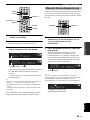
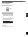
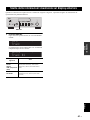
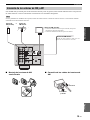
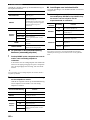
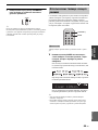
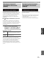
y
If the network connection is not set, turn the power ON to display “WAC” (Wireless Accessory Configuration) on the front panel and
trigger an automatic iOS device search. See “Sharing the iOS device setting” (p. 16) for details on the iOS device and network
connection.
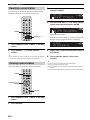
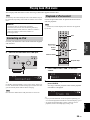
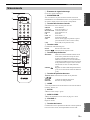
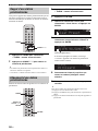
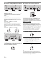
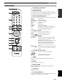
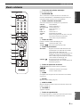
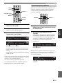
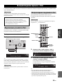
1 Information display
Displays the current status (such as input name).
You can switch the information that is displayed when you
press DISPLAY on the front panel (p. 41).
2 STEREO
Lights up when the unit is receiving a stereo FM radio
signal.
3 TUNED
Lights up when the unit is receiving an FM/AM radio
station signal.
4 Signal strength indicator
Lights up when the unit connects to a wireless network or
operates as an access point. The strength of the wireless
network signal can be verified by the indicator status.
5 Bluetooth indicator
Lights up when the unit is connecting to a Bluetooth
device.
6 Speaker indicators
“A” lights up when the SPEAKERS A output is enabled
and “B” lights up when the SPEAKERS B output is
enabled.
7 SLEEP
Lights up when the sleep timer is on.
8 MUTE
Blinks when audio is muted.
9 Volume indicator
Indicates the current volume.
0 Cursor indicators
Indicate the remote control cursor keys currently
operational.
y
You can change the brightness level of the front display by
pressing DIMMER on the front panel (p. 5).
Front display
VOL.
MUTE
TUNEDSTEREO
A
SLEEP
B
1 9
6
: :
2
3 7 854

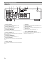
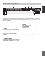
Controls and functions
8 En
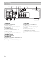
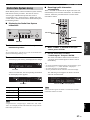
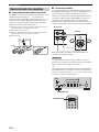
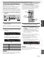
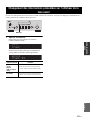
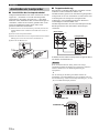
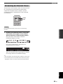
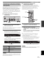
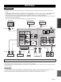
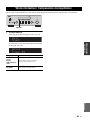
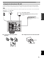
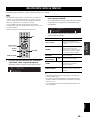
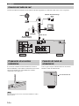
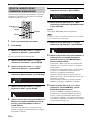
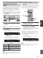
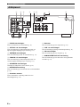
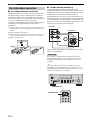
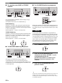
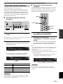
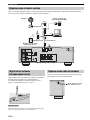
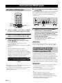
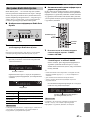
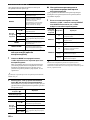
1 PHONO jacks
For connecting to a turntable (p. 11).
2 OPTICAL 1/2 jacks
For connecting to audio components equipped with
optical digital output (p. 11).
3 ANTENNA terminals
For connecting to FM and AM antennas (p. 13).
4 COAXIAL 1/2 jacks
For connecting to audio components equipped with a
coaxial digital output (p. 11).
5 SPEAKERS terminals
Used to connect speakers (p. 12).
6 NETWORK jack
For connecting to a network with a network cable (p. 14).
7 Wireless antenna
For connecting to a network device wirelessly (p. 14).
8 Power cable
For connecting to an AC wall outlet (p. 14).
9 LINE 1-3 jacks
For connecting to analog audio components (
p. 11
).
0 CD jacks
For connecting to a CD player (p. 11).
A SUBWOOFER PRE OUT jack
For connecting to a subwoofer with built-in amplifier
(p. 11).
Rear panel
A
B
SPEAKERS
NETWORK
COAXIAL
OPTICAL
FM AM
75Ω
ANTENNA
SUBWOOFER
PRE OUT
PHONO
IN
1
IN
OUT
2
1
2
1
2
IN
CD
LINE
OUT
3
SIGNAL
GND
3 5 68
A
1 2 4 7
9 :

Controls and functions
9 En
INTRODUCTION
English
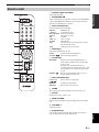
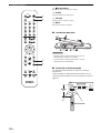
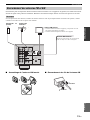
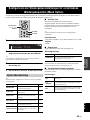
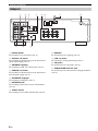
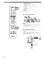
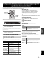
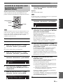
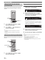
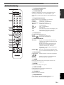
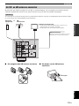
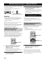
1 Infrared signal transmitter
Sends infrared signals.
2 SPEAKERS A/B
Turns on and off the set of speakers connected to the SPEAKERS
A and/or SPEAKERS B terminals on the rear panel of this unit
when the corresponding key is pressed.
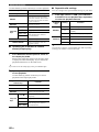
3 Input selection keys
Select an input source for playback.
PHONO PHONO jacks
COAX 1/2 COAXIAL1/2 jacks
BLUETOOTH Bluetooth connection
OPT 1/2 OPTICAL 1/2 jacks
CD CD jacks
LINE 1-3 LINE 1-3 jacks
TUNER FM/AM tuner
NET Network source (press repeatedly to select a
desired network source)
USB USB jack (on the front panel)
4 Radio keys
Operate the FM/AM radio (p. 24).
BAND Switches between FM and AM.
TUNING jj/ii Selects the radio frequency.
5 Preset keys
MEMORY Registers the current FM/AM station as a
preset when TUNER is selected as the input
source (p. 25).
Registers the current playback song or
streaming station as a preset when NET, USB
(except iPod) are selected as the input source
(p. 42).
PRESET j/i Recalls a preset FM/AM station (p. 26) or
song/streaming station (p. 42).
6 Menu operation keys
Cursor keys Select a menu or a parameter.
(B/C/D/E)
ENTER Confirms a selected item.
RETURN Returns to the previous state.
7 HOME
Moves up top level when selecting music files, folders, etc.
8 SETUP
Displays the “Setup” menu (p. 44).
9 NOW PLAYING
Displays music information when selecting music files, folders,
etc.
0 VOLUME +/-
Adjust the volume.
A Playback keys
Let you play back and perform other operations for network
sources, Bluetooth devices and USB devices.
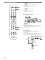
Remote control
LINE 1
OPT 1 OPT 2 CD
COAX 1 COAX 2
BLUETOOTH
NET USB
LINE 2 LINE 3
TUNER
PRESET
TUNING
BAND
MEMORY
SETUP
HOME
MUTENOW PLAYING
VOLUME
RETURN
ENTER
REPEAT
SHUFFLE
SLEEP
PHONO
B
A
SPEAKERS
OPTION
1
3
6
7
0
8
9
2
4
5
A

Controls and functions
10 En
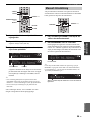
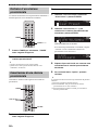
B A (power)
Turns on/off (standby) the unit.
C SLEEP
Sets the sleep timer (p. 23).
D OPTION
Displays the “Option” menu (p. 43).
E MUTE
Mutes the audio output.
■ Installing batteries
• Change all batteries if the operation range of the remote control
narrows.
• Before inserting new batteries, wipe the compartment clean.
■ Operation range
The remote controls transmit a directional infrared beam.
Be sure to aim the remote controls directly at the remote
control sensor on the front panel of this unit.
LINE 1
OPT 1 OPT 2 CD
COAX 1 COAX 2
BLUETOOTH
NET USB
LINE 2 LINE 3
TUNER
PRESET
TUNING
BAND
MEMORY
SETUP
HOME
MUTENOW PLAYING
VOLUME
RETURN
ENTER
REPEAT
SHUFFLE
SLEEP
PHONO
B
A
SPEAKERS
OPTION
B
C
D
E
Notes
30° 30°
Remote control
Approximately
6 m (20 ft)

11 En
PREPARATION
English
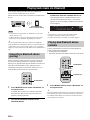
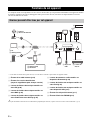
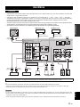
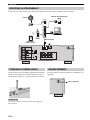
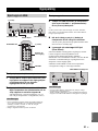
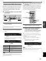
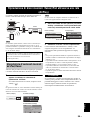
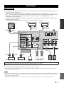
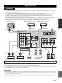
PREPARATION
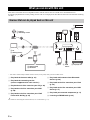
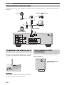
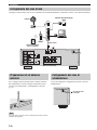
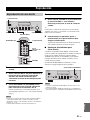
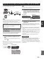
• Do not connect this unit or other components to the main power until all connections between components are complete.
• All connections must be correct: L (left) to L, R (right) to R, “+” to “+” and “–” to “–”. If the connections are faulty,
no sound will be heard from the speakers, and if the polarity of the speaker connections is incorrect, the sound will be
unnatural and lack bass. Refer to the owner’s manual for each of your components.
• Do not let bare speaker wires touch each other or any metal part of this unit. This could damage this unit and/or the speakers.
• Make sure to use RCA cables, optical cables to connect audio components.
y
• The PHONO jacks are designed for connecting a turntable with an MM cartridge.
• Connect your turntable to the GND terminal to reduce noise in the signal. However, for some turntables, you may hear less noise
without the GND connection.
• In order to prevent the audio signal from looping when an audio recording device is connected, the audio signal is not output from the
LINE 2 (OUT) jacks when LINE 2 is selected. Similarly, the audio signal is not output from the LINE 3 (OUT) jacks when LINE 3 is
selected.
• Do not bundle audio cables and speaker cables together with the power cable. Doing so may generate noise.
Connections
CAUTION
Only PCM signals can be input to the digital (OPTICAL/COAXIAL) jacks of this unit.
Notes
A
B
SPEAKERS
NETWORK
COAXIAL
OPTICAL
FM AM
75Ω
ANTENNA
SUBWOOFER
PRE OUT
PHONO
IN
1
IN
OUT
2
1
2
1
2
IN
CD
LINE
OUT
3
SIGNAL
GND
O C
Audio
input
Audio
output
Speakers B
Turntable
Audio
output
DVD player, etc.
GND
Audio output
(digital coaxial)
Audio output
(digital optical)
CD player, etc.
Audio
output
CD player
Subwoofer
CD recorder, etc.
Speakers A

12 En
Connections
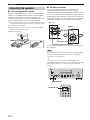
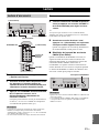
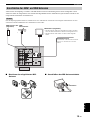
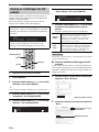
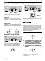
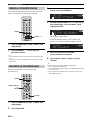
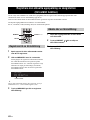
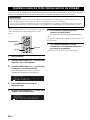
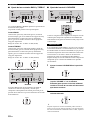
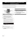
■ Connecting speaker cables
Speaker cables have two wires. One is for connecting the
negative (–) terminal of the unit and the speaker, and the
other is for the positive (+) terminal. If the wires are
colored to prevent confusion, connect the black wire to the
negative and the other wire to the positive terminal.
a
Remove approximately 10 mm (3/8”) of insulation from the ends of
the speaker cable and twist the bare wires of the cable firmly together.
b Loosen the speaker terminal.
c Insert the bare wires of the cable into the gap on the side (upper
right or bottom left) of the terminal.
d Tighten the terminal.
■ Bi-wire connection
Bi-wire connection separates the woofer from the
combined midrange and tweeter section. A bi-wire
compatible speaker has four binding post terminals. These
two sets of terminals allow the speaker to be split into two
independent sections. With these connections, the mid and
high frequency drivers are connected to one set of terminals
and the low frequency driver to another set of terminals.
Connect the other speaker to the other set of terminals in
the same way.
When making bi-wire connections, remove the shorting bridges
or cables on the speaker. Refer to the speakers’ instruction
manuals for more information.
y
To use the bi-wire connections, press SPEAKERS A and
SPEAKERS B on the front panel or on the remote control so that
both speaker indicators (“A” and “B”) light up on the front
display.
Connecting the speakers
aa
b
b
d
d
c
c
10 mm
(3/8")
Note
A
B
SPEAK
This unit
Speaker
VOLUME
PURE DIRECT
RETURN
CONNECT
PUSH - ENTER
TUNINGPRESET
BAND
MEMORY CLEAR
BASSINPUT
5V
1A
BALANCE
LR
TREBLE
LOUDNESS
FLAT
-30dB
DIMMER MODE
DISPLAY
SELECT
PHONES
SPEAKERS
AB
SPEAKERS A/B
OPT 1 OPT 2 CD
COAX 1 COAX 2
BLUETOOTH
SLEEP
PHONO
B
A
SPEAKERS
SPEAKERS A/B

13 En
Connections
PREPARATION
English
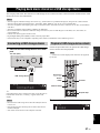
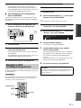
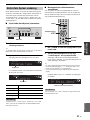
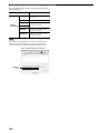
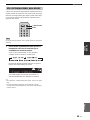
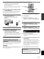
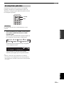
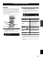
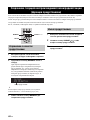
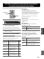
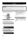
The antennas for receiving FM and AM broadcasts are included with this unit. In general, these antennas should provide
sufficient signal strength. Connect each antenna correctly to the designated terminals.
If you experience poor reception quality, install an outdoor antenna. Consult the nearest authorized Yamaha dealer or service center
about outdoor antennas.
■ Assembling the supplied AM antenna ■ Connecting the wires of the AM antenna
Connecting the FM and AM antennas
Note
COAXIAL
OPTICAL
FM AM
75Ω
ANTENNA
SUBWOOFER
PRE OUT
PHONO
IN
1
IN
OUT
2
1
2
1
2
IN
CD
LINE
OUT
3
SIGNAL
GND
FM antenna
(included)
Outdoor AM antenna
Use 5 to 10 m of vinyl-covered wire extended
outdoors from a window.
Outdoor
FM antenna
• The AM antenna should always be connected, even if an outdoor
AM antenna is connected to this unit.
• The AM antenna should be placed away from this unit.
AM antenna (included)
or
Insert
2
Hold down
1

14 En
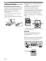
Connections
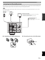
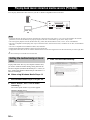
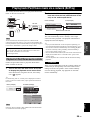
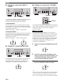
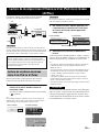
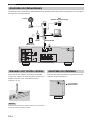
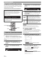
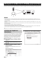
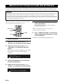
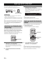
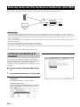
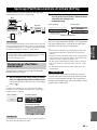
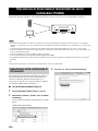
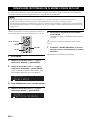
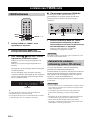
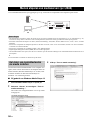
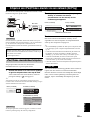
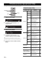
Connect the unit to your router with a commercially-available STP network cable (CAT-5 or higher straight cable).
If you connect the unit wirelessly, erect the wireless
antenna. For information on how to connect the unit to a
wireless network, see “Connecting to network” (p. 15).
Do not apply excessive force on the wireless antenna. Doing so
may damage the antenna.
After all the connections are complete, plug in the power
cable.
Connecting the network cable
A
B
SPEAKERS
NETWORK
COAXIAL
OPTICAL
FM AM
75Ω
ANTENNA
SUBWOOFER
PRE OUT
PHONO
IN
1
IN
OUT
2
1
2
1
2
IN
CD
LINE
OUT
3
SIGNAL
GND
LAN
WAN
Network Attached Storage
(NAS)
Internet
Modem
Router
Network cable
PC
This unit (rear)
Mobile device
(such as iPhone)
Preparing a wireless antenna
Note
WIRELES
S
WORK
Connecting power cable
To an AC wall outlet

Connecting to network
15 En
PREPARATION
English
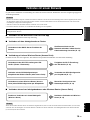
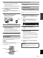
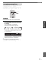
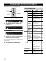
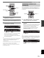
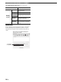
There are several methods to connect the unit to a network. Select a connection method according to your environment.
• Some security software installed on your PC or the firewall settings of network devices (such as a router) may block the access of the
unit to the network devices or the Internet. In these cases, configure the security software or firewall settings appropriately.
• Each server must be connected to the same subnet as the unit.
• To use the service via the Internet, broadband connection is strongly recommended.
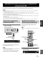
■ Connecting with the MusicCast CONTROLLER app
See MusicCast Setup Guide for details.
■ Connecting with the wired router
■ Connecting with a wireless router (access point)
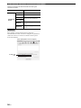
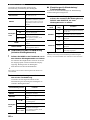
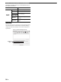
Connect to the network with the method listed below that corresponds to your environment.
■ Connecting without a wired router or wireless router (access point)
When the unit is connected to the network with Wireless Direct, it cannot connect to any other wireless router (access point). To play
back contents from the Internet, connect this unit to a network with a wired router or wireless router (access point).
Connecting to network
Notes
When playing a high-resolution audio source via the network, we recommend connecting with a wired router for stable playback.
Note
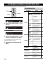
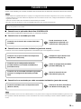
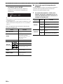
Connecting using the DHCP server function of the
router
You can connect to the network by
simply making a wired connection
(p. 14)
Connecting using the Wi-Fi setting of the iOS
device (iPhone / iPod touch)
Share the Wi-Fi setting of the iOS
device (p. 16)
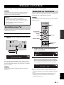
Connecting using WPS push button configuration
on the wireless router (or access point)
Use the WPS push button
configuration (p. 17)
Connecting with a wireless router (access point)
without WPS push button configuration
Set the network connection
manually (p. 18)
Connecting wirelessly to a mobile device
(Wireless Direct)
Connect wirelessly with Wireless
Direct (p. 19)

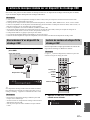
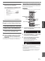
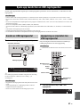
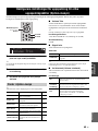
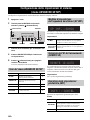
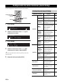
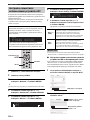
16 En
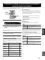
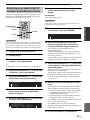
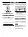
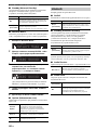
Connecting to network
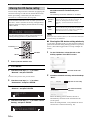
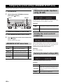
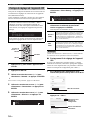
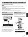
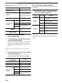
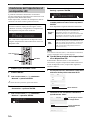
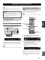
You can easily setup a wireless connection by applying the
connection settings on iOS devices (iPhone/iPod touch).
Before proceeding, confirm that your iOS device is
connected to a wireless router (access point).
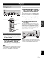
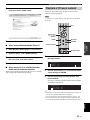
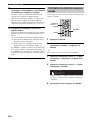
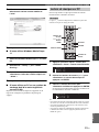
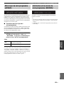
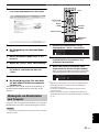
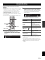
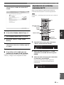
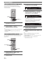
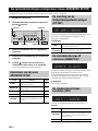
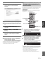
1 Press A to turn on this unit.
2 Press SETUP.
3 Use the cursor keys (B / C) to select
“Network” and press ENTER.
y
To return to the previous state, press RETURN.
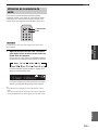
4 Use the cursor keys (B / C) to select
“Connection” and press ENTER.
5 Use the cursor keys (B / C) to select
“Wireless” and press ENTER.
6 Use the cursor keys (B / C) to select “Share
Setting” and press ENTER.
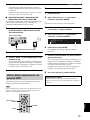
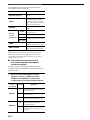
7 Use the cursor keys (B / C) to select the
desired connection method and press
ENTER.
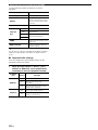
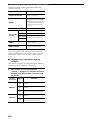
The following connection methods are available.
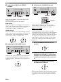
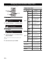
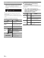
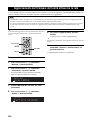
When you select “Wireless (WAC)” as the connection method, all
network settings are initialized.
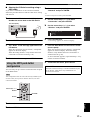
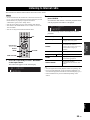
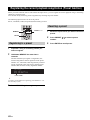
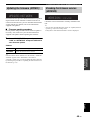
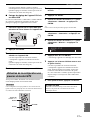
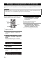
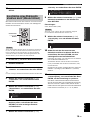
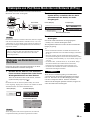
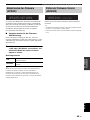
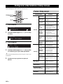
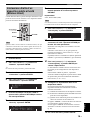
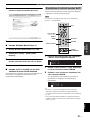
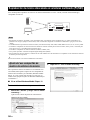
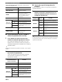
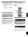
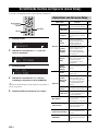
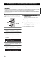
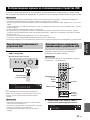
■ Sharing the iOS device setting wirelessly
If you select “Wireless (WAC)” as the connection method,
perform the network setting sharing operation on your iOS
device. (The following procedure is a setup example for
iOS 8.)
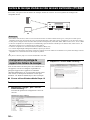
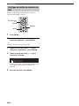
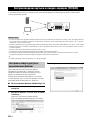
1 On the iOS device, select the unit as the
AirPlay speaker in the Wi-Fi screen.
2 Check the network currently selected and tap
“Next”.
When the sharing process finishes, the unit is
automatically connected to the selected network
(access point).
When the setting finishes, verify whether the unit is
connected to a wireless network (p. 20).
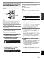
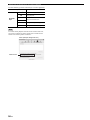
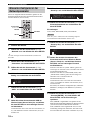
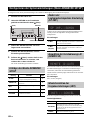
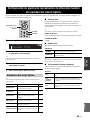
Sharing the iOS device setting
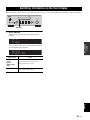
If the network connection is not set, when you turn on
this unit, “WAC” (Wireless Accessory Configuration)
appears on the front display, and the iOS device setting
can be shared.
To share the iOS device setting, perform the network
setting sharing operation on your iOS device.
R-N602 XXXXXX
WAC
PRESET
MEMORY
SETUP
HOME
MUTENOW PLAYING
VOLUME
RETURN
ENTER
OPTION
RETURN
SETUP
ENTER
Cursor keys
B
/
C
WPS
WIRELESS
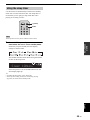
Wireless(WAC)
SHARE
Wireless
(WAC)
You can apply the connection settings on the iOS
device to the unit using a wireless connection. For
details, see “Sharing the iOS device setting
wirelessly”. (You need iOS device with iOS 7 or
later.)
USB
Cable
You can apply the connection settings on the iOS
device to the unit using a USB cable. For details, see
“Sharing the iOS device setting using a USB cable”.
(You need iOS device with iOS 5 or later.)
Note
The name of this unit
Tap here to start setup
The network currently
selected
Sidan laddas ...
Sidan laddas ...
Sidan laddas ...
Sidan laddas ...
Sidan laddas ...
Sidan laddas ...
Sidan laddas ...
Sidan laddas ...
Sidan laddas ...
Sidan laddas ...
Sidan laddas ...
Sidan laddas ...
Sidan laddas ...
Sidan laddas ...
Sidan laddas ...
Sidan laddas ...
Sidan laddas ...
Sidan laddas ...
Sidan laddas ...
Sidan laddas ...
Sidan laddas ...
Sidan laddas ...
Sidan laddas ...
Sidan laddas ...
Sidan laddas ...
Sidan laddas ...
Sidan laddas ...
Sidan laddas ...
Sidan laddas ...
Sidan laddas ...
Sidan laddas ...
Sidan laddas ...
Sidan laddas ...
Sidan laddas ...
Sidan laddas ...
Sidan laddas ...
Sidan laddas ...
Sidan laddas ...
Sidan laddas ...
Sidan laddas ...
Sidan laddas ...
Sidan laddas ...
Sidan laddas ...
Sidan laddas ...
Sidan laddas ...
Sidan laddas ...
Sidan laddas ...
Sidan laddas ...
Sidan laddas ...
Sidan laddas ...
Sidan laddas ...
Sidan laddas ...
Sidan laddas ...
Sidan laddas ...
Sidan laddas ...
Sidan laddas ...
Sidan laddas ...
Sidan laddas ...
Sidan laddas ...
Sidan laddas ...
Sidan laddas ...
Sidan laddas ...
Sidan laddas ...
Sidan laddas ...
Sidan laddas ...
Sidan laddas ...
Sidan laddas ...
Sidan laddas ...
Sidan laddas ...
Sidan laddas ...
Sidan laddas ...
Sidan laddas ...
Sidan laddas ...
Sidan laddas ...
Sidan laddas ...
Sidan laddas ...
Sidan laddas ...
Sidan laddas ...
Sidan laddas ...
Sidan laddas ...
Sidan laddas ...
Sidan laddas ...
Sidan laddas ...
Sidan laddas ...
Sidan laddas ...
Sidan laddas ...
Sidan laddas ...
Sidan laddas ...
Sidan laddas ...
Sidan laddas ...
Sidan laddas ...
Sidan laddas ...
Sidan laddas ...
Sidan laddas ...
Sidan laddas ...
Sidan laddas ...
Sidan laddas ...
Sidan laddas ...
Sidan laddas ...
Sidan laddas ...
Sidan laddas ...
Sidan laddas ...
Sidan laddas ...
Sidan laddas ...
Sidan laddas ...
Sidan laddas ...
Sidan laddas ...
Sidan laddas ...
Sidan laddas ...
Sidan laddas ...
Sidan laddas ...
Sidan laddas ...
Sidan laddas ...
Sidan laddas ...
Sidan laddas ...
Sidan laddas ...
Sidan laddas ...
Sidan laddas ...
Sidan laddas ...
Sidan laddas ...
Sidan laddas ...
Sidan laddas ...
Sidan laddas ...
Sidan laddas ...
Sidan laddas ...
Sidan laddas ...
Sidan laddas ...
Sidan laddas ...
Sidan laddas ...
Sidan laddas ...
Sidan laddas ...
Sidan laddas ...
Sidan laddas ...
Sidan laddas ...
Sidan laddas ...
Sidan laddas ...
Sidan laddas ...
Sidan laddas ...
Sidan laddas ...
Sidan laddas ...
Sidan laddas ...
Sidan laddas ...
Sidan laddas ...
Sidan laddas ...
Sidan laddas ...
Sidan laddas ...
Sidan laddas ...
Sidan laddas ...
Sidan laddas ...
Sidan laddas ...
Sidan laddas ...
Sidan laddas ...
Sidan laddas ...
Sidan laddas ...
Sidan laddas ...
Sidan laddas ...
Sidan laddas ...
Sidan laddas ...
Sidan laddas ...
Sidan laddas ...
Sidan laddas ...
Sidan laddas ...
Sidan laddas ...
Sidan laddas ...
Sidan laddas ...
Sidan laddas ...
Sidan laddas ...
Sidan laddas ...
Sidan laddas ...
Sidan laddas ...
Sidan laddas ...
Sidan laddas ...
Sidan laddas ...
Sidan laddas ...
Sidan laddas ...
Sidan laddas ...
Sidan laddas ...
Sidan laddas ...
Sidan laddas ...
Sidan laddas ...
Sidan laddas ...
Sidan laddas ...
Sidan laddas ...
Sidan laddas ...
Sidan laddas ...
Sidan laddas ...
Sidan laddas ...
Sidan laddas ...
Sidan laddas ...
Sidan laddas ...
Sidan laddas ...
Sidan laddas ...
Sidan laddas ...
Sidan laddas ...
Sidan laddas ...
Sidan laddas ...
Sidan laddas ...
Sidan laddas ...
Sidan laddas ...
Sidan laddas ...
Sidan laddas ...
Sidan laddas ...
Sidan laddas ...
Sidan laddas ...
Sidan laddas ...
Sidan laddas ...
Sidan laddas ...
Sidan laddas ...
Sidan laddas ...
Sidan laddas ...
Sidan laddas ...
Sidan laddas ...
Sidan laddas ...
Sidan laddas ...
Sidan laddas ...
Sidan laddas ...
Sidan laddas ...
Sidan laddas ...
Sidan laddas ...
Sidan laddas ...
Sidan laddas ...
Sidan laddas ...
Sidan laddas ...
Sidan laddas ...
Sidan laddas ...
Sidan laddas ...
Sidan laddas ...
Sidan laddas ...
Sidan laddas ...
Sidan laddas ...
Sidan laddas ...
Sidan laddas ...
Sidan laddas ...
Sidan laddas ...
Sidan laddas ...
Sidan laddas ...
Sidan laddas ...
Sidan laddas ...
Sidan laddas ...
Sidan laddas ...
Sidan laddas ...
Sidan laddas ...
Sidan laddas ...
Sidan laddas ...
Sidan laddas ...
Sidan laddas ...
Sidan laddas ...
Sidan laddas ...
Sidan laddas ...
Sidan laddas ...
Sidan laddas ...
Sidan laddas ...
Sidan laddas ...
Sidan laddas ...
Sidan laddas ...
Sidan laddas ...
Sidan laddas ...
Sidan laddas ...
Sidan laddas ...
Sidan laddas ...
Sidan laddas ...
Sidan laddas ...
Sidan laddas ...
Sidan laddas ...
Sidan laddas ...
Sidan laddas ...
Sidan laddas ...
Sidan laddas ...
Sidan laddas ...
Sidan laddas ...
Sidan laddas ...
Sidan laddas ...
Sidan laddas ...
Sidan laddas ...
Sidan laddas ...
Sidan laddas ...
Sidan laddas ...
Sidan laddas ...
Sidan laddas ...
Sidan laddas ...
Sidan laddas ...
Sidan laddas ...
Sidan laddas ...
Sidan laddas ...
Sidan laddas ...
Sidan laddas ...
Sidan laddas ...
Sidan laddas ...
Sidan laddas ...
Sidan laddas ...
Sidan laddas ...
Sidan laddas ...
Sidan laddas ...
Sidan laddas ...
Sidan laddas ...
Sidan laddas ...
Sidan laddas ...
Sidan laddas ...
Sidan laddas ...
Sidan laddas ...
Sidan laddas ...
Sidan laddas ...
Sidan laddas ...
Sidan laddas ...
Sidan laddas ...
Sidan laddas ...
Sidan laddas ...
Sidan laddas ...
Sidan laddas ...
Sidan laddas ...
Sidan laddas ...
Sidan laddas ...
Sidan laddas ...
Sidan laddas ...
Sidan laddas ...
Sidan laddas ...
Sidan laddas ...
Sidan laddas ...
Sidan laddas ...
Sidan laddas ...
Sidan laddas ...
Sidan laddas ...
Sidan laddas ...
Sidan laddas ...
Sidan laddas ...
Sidan laddas ...
Sidan laddas ...
Sidan laddas ...
Sidan laddas ...
Sidan laddas ...
Sidan laddas ...
Sidan laddas ...
Sidan laddas ...
Sidan laddas ...
Sidan laddas ...
Sidan laddas ...
Sidan laddas ...
Sidan laddas ...
Sidan laddas ...
Sidan laddas ...
Sidan laddas ...
Sidan laddas ...
Sidan laddas ...
Sidan laddas ...
Sidan laddas ...
Sidan laddas ...
Sidan laddas ...
Sidan laddas ...
Sidan laddas ...
Sidan laddas ...
Sidan laddas ...
Sidan laddas ...
Sidan laddas ...
Sidan laddas ...
Sidan laddas ...
Sidan laddas ...
Sidan laddas ...
Sidan laddas ...
Sidan laddas ...
Sidan laddas ...
Sidan laddas ...
Sidan laddas ...
Sidan laddas ...
Sidan laddas ...
Sidan laddas ...
Sidan laddas ...
Sidan laddas ...
Sidan laddas ...
Sidan laddas ...
Sidan laddas ...
Sidan laddas ...
Sidan laddas ...
Sidan laddas ...
Sidan laddas ...
Sidan laddas ...
Sidan laddas ...
Sidan laddas ...
Sidan laddas ...
Sidan laddas ...
Sidan laddas ...
Sidan laddas ...
Sidan laddas ...
Sidan laddas ...
Sidan laddas ...
Sidan laddas ...
Sidan laddas ...
Sidan laddas ...
Sidan laddas ...
Sidan laddas ...
Sidan laddas ...
Sidan laddas ...
Sidan laddas ...
Sidan laddas ...
Sidan laddas ...
Sidan laddas ...
Sidan laddas ...
Sidan laddas ...
Sidan laddas ...
Sidan laddas ...
Sidan laddas ...
Sidan laddas ...
Sidan laddas ...
Sidan laddas ...
Sidan laddas ...
Sidan laddas ...
Sidan laddas ...
Sidan laddas ...
Sidan laddas ...
Sidan laddas ...
Sidan laddas ...
Sidan laddas ...
Sidan laddas ...
Sidan laddas ...
Sidan laddas ...
Sidan laddas ...
Sidan laddas ...
Sidan laddas ...
Sidan laddas ...
Sidan laddas ...
Sidan laddas ...
Sidan laddas ...
Sidan laddas ...
Sidan laddas ...
Sidan laddas ...
Sidan laddas ...
Sidan laddas ...
Sidan laddas ...
Sidan laddas ...
Sidan laddas ...
Sidan laddas ...
Sidan laddas ...
Sidan laddas ...
Sidan laddas ...
Sidan laddas ...
Sidan laddas ...
Sidan laddas ...
Sidan laddas ...
Sidan laddas ...
Sidan laddas ...
Sidan laddas ...
Sidan laddas ...
Sidan laddas ...
Sidan laddas ...
Sidan laddas ...
Sidan laddas ...
Sidan laddas ...
Sidan laddas ...
Sidan laddas ...
Sidan laddas ...
Sidan laddas ...
Sidan laddas ...
Sidan laddas ...
Sidan laddas ...
Sidan laddas ...
Sidan laddas ...
Sidan laddas ...
Sidan laddas ...
Sidan laddas ...
Sidan laddas ...
Sidan laddas ...
Sidan laddas ...
Sidan laddas ...
Sidan laddas ...
Sidan laddas ...
Sidan laddas ...
Sidan laddas ...
Sidan laddas ...
Sidan laddas ...
Sidan laddas ...
Sidan laddas ...
Sidan laddas ...
Sidan laddas ...
Sidan laddas ...
Sidan laddas ...
Sidan laddas ...
Sidan laddas ...
Sidan laddas ...
Sidan laddas ...
Sidan laddas ...
Sidan laddas ...
Sidan laddas ...
Sidan laddas ...
Sidan laddas ...
Sidan laddas ...
Sidan laddas ...
Sidan laddas ...
Sidan laddas ...
Sidan laddas ...
Sidan laddas ...
Sidan laddas ...
Sidan laddas ...
Sidan laddas ...
Sidan laddas ...
Sidan laddas ...
-
 1
1
-
 2
2
-
 3
3
-
 4
4
-
 5
5
-
 6
6
-
 7
7
-
 8
8
-
 9
9
-
 10
10
-
 11
11
-
 12
12
-
 13
13
-
 14
14
-
 15
15
-
 16
16
-
 17
17
-
 18
18
-
 19
19
-
 20
20
-
 21
21
-
 22
22
-
 23
23
-
 24
24
-
 25
25
-
 26
26
-
 27
27
-
 28
28
-
 29
29
-
 30
30
-
 31
31
-
 32
32
-
 33
33
-
 34
34
-
 35
35
-
 36
36
-
 37
37
-
 38
38
-
 39
39
-
 40
40
-
 41
41
-
 42
42
-
 43
43
-
 44
44
-
 45
45
-
 46
46
-
 47
47
-
 48
48
-
 49
49
-
 50
50
-
 51
51
-
 52
52
-
 53
53
-
 54
54
-
 55
55
-
 56
56
-
 57
57
-
 58
58
-
 59
59
-
 60
60
-
 61
61
-
 62
62
-
 63
63
-
 64
64
-
 65
65
-
 66
66
-
 67
67
-
 68
68
-
 69
69
-
 70
70
-
 71
71
-
 72
72
-
 73
73
-
 74
74
-
 75
75
-
 76
76
-
 77
77
-
 78
78
-
 79
79
-
 80
80
-
 81
81
-
 82
82
-
 83
83
-
 84
84
-
 85
85
-
 86
86
-
 87
87
-
 88
88
-
 89
89
-
 90
90
-
 91
91
-
 92
92
-
 93
93
-
 94
94
-
 95
95
-
 96
96
-
 97
97
-
 98
98
-
 99
99
-
 100
100
-
 101
101
-
 102
102
-
 103
103
-
 104
104
-
 105
105
-
 106
106
-
 107
107
-
 108
108
-
 109
109
-
 110
110
-
 111
111
-
 112
112
-
 113
113
-
 114
114
-
 115
115
-
 116
116
-
 117
117
-
 118
118
-
 119
119
-
 120
120
-
 121
121
-
 122
122
-
 123
123
-
 124
124
-
 125
125
-
 126
126
-
 127
127
-
 128
128
-
 129
129
-
 130
130
-
 131
131
-
 132
132
-
 133
133
-
 134
134
-
 135
135
-
 136
136
-
 137
137
-
 138
138
-
 139
139
-
 140
140
-
 141
141
-
 142
142
-
 143
143
-
 144
144
-
 145
145
-
 146
146
-
 147
147
-
 148
148
-
 149
149
-
 150
150
-
 151
151
-
 152
152
-
 153
153
-
 154
154
-
 155
155
-
 156
156
-
 157
157
-
 158
158
-
 159
159
-
 160
160
-
 161
161
-
 162
162
-
 163
163
-
 164
164
-
 165
165
-
 166
166
-
 167
167
-
 168
168
-
 169
169
-
 170
170
-
 171
171
-
 172
172
-
 173
173
-
 174
174
-
 175
175
-
 176
176
-
 177
177
-
 178
178
-
 179
179
-
 180
180
-
 181
181
-
 182
182
-
 183
183
-
 184
184
-
 185
185
-
 186
186
-
 187
187
-
 188
188
-
 189
189
-
 190
190
-
 191
191
-
 192
192
-
 193
193
-
 194
194
-
 195
195
-
 196
196
-
 197
197
-
 198
198
-
 199
199
-
 200
200
-
 201
201
-
 202
202
-
 203
203
-
 204
204
-
 205
205
-
 206
206
-
 207
207
-
 208
208
-
 209
209
-
 210
210
-
 211
211
-
 212
212
-
 213
213
-
 214
214
-
 215
215
-
 216
216
-
 217
217
-
 218
218
-
 219
219
-
 220
220
-
 221
221
-
 222
222
-
 223
223
-
 224
224
-
 225
225
-
 226
226
-
 227
227
-
 228
228
-
 229
229
-
 230
230
-
 231
231
-
 232
232
-
 233
233
-
 234
234
-
 235
235
-
 236
236
-
 237
237
-
 238
238
-
 239
239
-
 240
240
-
 241
241
-
 242
242
-
 243
243
-
 244
244
-
 245
245
-
 246
246
-
 247
247
-
 248
248
-
 249
249
-
 250
250
-
 251
251
-
 252
252
-
 253
253
-
 254
254
-
 255
255
-
 256
256
-
 257
257
-
 258
258
-
 259
259
-
 260
260
-
 261
261
-
 262
262
-
 263
263
-
 264
264
-
 265
265
-
 266
266
-
 267
267
-
 268
268
-
 269
269
-
 270
270
-
 271
271
-
 272
272
-
 273
273
-
 274
274
-
 275
275
-
 276
276
-
 277
277
-
 278
278
-
 279
279
-
 280
280
-
 281
281
-
 282
282
-
 283
283
-
 284
284
-
 285
285
-
 286
286
-
 287
287
-
 288
288
-
 289
289
-
 290
290
-
 291
291
-
 292
292
-
 293
293
-
 294
294
-
 295
295
-
 296
296
-
 297
297
-
 298
298
-
 299
299
-
 300
300
-
 301
301
-
 302
302
-
 303
303
-
 304
304
-
 305
305
-
 306
306
-
 307
307
-
 308
308
-
 309
309
-
 310
310
-
 311
311
-
 312
312
-
 313
313
-
 314
314
-
 315
315
-
 316
316
-
 317
317
-
 318
318
-
 319
319
-
 320
320
-
 321
321
-
 322
322
-
 323
323
-
 324
324
-
 325
325
-
 326
326
-
 327
327
-
 328
328
-
 329
329
-
 330
330
-
 331
331
-
 332
332
-
 333
333
-
 334
334
-
 335
335
-
 336
336
-
 337
337
-
 338
338
-
 339
339
-
 340
340
-
 341
341
-
 342
342
-
 343
343
-
 344
344
-
 345
345
-
 346
346
-
 347
347
-
 348
348
-
 349
349
-
 350
350
-
 351
351
-
 352
352
-
 353
353
-
 354
354
-
 355
355
-
 356
356
-
 357
357
-
 358
358
-
 359
359
-
 360
360
-
 361
361
-
 362
362
-
 363
363
-
 364
364
-
 365
365
-
 366
366
-
 367
367
-
 368
368
-
 369
369
-
 370
370
-
 371
371
-
 372
372
-
 373
373
-
 374
374
-
 375
375
-
 376
376
-
 377
377
-
 378
378
-
 379
379
-
 380
380
-
 381
381
-
 382
382
-
 383
383
-
 384
384
-
 385
385
-
 386
386
-
 387
387
-
 388
388
-
 389
389
-
 390
390
-
 391
391
-
 392
392
-
 393
393
-
 394
394
-
 395
395
-
 396
396
-
 397
397
-
 398
398
-
 399
399
-
 400
400
-
 401
401
-
 402
402
-
 403
403
-
 404
404
-
 405
405
-
 406
406
-
 407
407
-
 408
408
-
 409
409
-
 410
410
-
 411
411
-
 412
412
-
 413
413
-
 414
414
-
 415
415
-
 416
416
-
 417
417
-
 418
418
-
 419
419
-
 420
420
-
 421
421
-
 422
422
-
 423
423
-
 424
424
-
 425
425
-
 426
426
-
 427
427
-
 428
428
-
 429
429
-
 430
430
-
 431
431
-
 432
432
-
 433
433
-
 434
434
-
 435
435
-
 436
436
-
 437
437
-
 438
438
-
 439
439
-
 440
440
-
 441
441
-
 442
442
-
 443
443
-
 444
444
-
 445
445
-
 446
446
-
 447
447
-
 448
448
-
 449
449
-
 450
450
-
 451
451
-
 452
452
-
 453
453
-
 454
454
-
 455
455
-
 456
456
-
 457
457
-
 458
458
-
 459
459
-
 460
460
-
 461
461
-
 462
462
-
 463
463
-
 464
464
-
 465
465
-
 466
466
-
 467
467
-
 468
468
-
 469
469
-
 470
470
-
 471
471
-
 472
472
-
 473
473
-
 474
474
-
 475
475
-
 476
476
-
 477
477
-
 478
478
-
 479
479
-
 480
480
-
 481
481
-
 482
482
-
 483
483
-
 484
484
-
 485
485
-
 486
486
-
 487
487
-
 488
488
-
 489
489
-
 490
490
-
 491
491
-
 492
492
-
 493
493
-
 494
494
-
 495
495
-
 496
496
-
 497
497
-
 498
498
-
 499
499
-
 500
500
-
 501
501
-
 502
502
-
 503
503
-
 504
504
-
 505
505
-
 506
506
-
 507
507
-
 508
508
-
 509
509
-
 510
510
-
 511
511
-
 512
512
-
 513
513
-
 514
514


Yamaha R-N602 Bruksanvisning
- Kategori
- Mottagare för bilmedia
- Typ
- Bruksanvisning
på andra språk
- italiano: Yamaha R-N602 Manuale del proprietario
- Deutsch: Yamaha R-N602 Bedienungsanleitung
- français: Yamaha R-N602 Le manuel du propriétaire
- Türkçe: Yamaha R-N602 El kitabı
- English: Yamaha R-N602 Owner's manual
- dansk: Yamaha R-N602 Brugervejledning
- русский: Yamaha R-N602 Инструкция по применению
- suomi: Yamaha R-N602 Omistajan opas
- Nederlands: Yamaha R-N602 de handleiding
Relaterade papper
-
Yamaha R-N602 Black Användarmanual
-
-
Yamaha RX-A1080 Bruksanvisning
-
Yamaha RX-A1070 Bruksanvisning
-
-
Yamaha RX-A2080 Bruksanvisning
-
-
Yamaha RX-A2070BL Användarmanual
-
Yamaha RX-A3060 Användarmanual
-
Yamaha R-N303D Bruksanvisning