
Notice simplifiée
Module de connexion
AS-i
ASI-MV-4A-Z et
ASI-MF-4A-Z
ASI-MV-2E2A-Z et
ASI-MF-2E2A-Z
ASI-MV-2E1A-Z et
Breve descrizione
Connettore Combi
AS-i ASI-MV-4A-Z e
ASI-MF-4A-Z
ASI-MV-2E2A-Z e
ASI-MF-2E2A-Z
ASI-MV-2E1A-Z e
ASI-MF-2E1A-Z
Beskrivning
AS-i kombikontakt
ASI-MV-4A-Z och
ASI-MF-4A-Z
ASI-MV-2E2A-Z och
ASI-MF-2E2A-Z
ASI-MV-2E1A-Z och
ASI-MF-2E1A-Z
Breve descripción
Zócalo AS-i combi
ASI-MV-4A-Z y
ASI-MF-4A-Z
ASI-MV-2E2A-Z y
ASI-MF-2E2A-Z
ASI-MV-2E1A-Z y
ASI-MF-2E1A-Z
9801b
354 403
Kurzbeschreibung
AS-i-Kombidose
ASI-MV-4A-Z und
ASI-MF-4A-Z
ASI-MV-2E2A-Z und
ASI-MF-2E2A-Z
ASI-MV-2E1A-Z und
ASI-MF-2E1A-Z
Brief description
AS-i combi-socket
ASI-MV-4A-Z and
ASI-MF-4A-Z
ASI-MV-2E2A-Z and
ASI-MF-2E2A-Z
ASI-MV-2E1A-Z and
ASI-MF-2E1A-Z

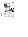
Deutsch . . . . . . . . . . . . . . . . . . . . . . . . . . . . . . . . . . . . . . 3
English. . . . . . . . . . . . . . . . . . . . . . . . . . . . . . . . . . . . . . . 11
Español . . . . . . . . . . . . . . . . . . . . . . . . . . . . . . . . . . . . . 19
Français. . . . . . . . . . . . . . . . . . . . . . . . . . . . . . . . . . . . . 27
Italiano . . . . . . . . . . . . . . . . . . . . . . . . . . . . . . . . . . . . . . 35
Svenska . . . . . . . . . . . . . . . . . . . . . . . . . . . . . . . . . . . . . 43
(Festo AG & Co., D-73726 Esslingen, 1998)
ASI-M..-...-Z
9801b 2

1
Allgemeine Hinweise
Lesen Sie diese Kurzbeschreibung vollständig durch. Beginnen
Sie erst dann mit dem Einbau.
Bestimmungsgemäßer Einsatz von AS-i-Produkten
•• AS-i-Produkte sind ausschließlich für den Einsatz in Bussy-
stemen gemäß der AS-i-Spezifikation geeignet. Jede andere
Verwendung ist nicht bestimmungsgemäß.
•• AS-i-Bussysteme und AS-i-Kombidosen dürfen nur von hier-
für geschultem Fachpersonal installiert werden.
•• Ausführliche Angaben zur Konzeption und Adressierung Ih-
res AS-i-Bussystems finden Sie in der Beschreibung Ihres
AS-i-Masters.
Vor der Inbetriebnahme
•• Schalten sie die Spannung aus, bevor Sie Steckverbinder
zusammenstecken oder trennen (Funktionsschädigung).
•• Nehmen Sie nur komplett montierte und angeschlossene
Kombidosen in Betrieb.
•• Empfehlung zur Symmetrierung/Erdung: Die AS-i-Schaltun-
gen der Kombidosen sind so ausgelegt, daß sie ohne zu-
sätzliche Erdung für Industrieumgebungen geeignet sind.
Die von der EMV-Richtlinie der EG vorgegebenen Werte er-
reichen Sie jedoch nur durch Anschluß einer zusätzlichen
Erdung an der M3-Erdungsschraube. Dies verbessert auch
die Symmetrierung der Schaltung und erhöht deren Stabilität.
•
Fällt der AS-i-Master während des Betriebs aus, bleiben
die Ausgänge gesetzt.
•
Wird die AS-i-Spannung zu einem Slave unterbrochen,
werden die Ausgänge abgeschaltet.
Deutsch
ASI-M..-...-Z
9801b 3

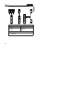
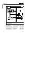
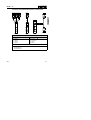
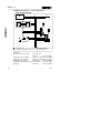
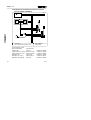
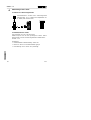
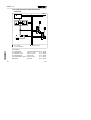
2
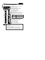
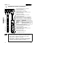
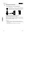
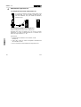
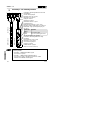
Anschluß- und Anzeigeelemente
Steckdose (Bauform/Steckbild abhängig von
Bestellung)
Gelbe LED für Magnetspule
Befestigungsschraube (max. 0,5 Nm)
Bezeichnungsschild (z. B. für Adresse)
Numerierung des Ausgangs
Numerierung der Eingänge
Sensorstecker M12 für 2 Sensoren
Erdungsanschluß M3
Betriebsspannungsanschluß 24 VDC (Zusatz-
versorgung, dadurch Ventile bei NOT-AUS ab-
schaltbar. Keine Spannungsversorgung über
AS-i-Bus)
BUS-LED
(grün)
Bedeutung
an
aus
AS-i-Spannung vorhanden
keine AS-i-Spannung am Bus
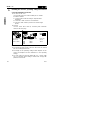
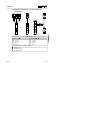
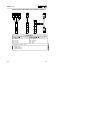
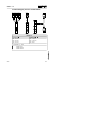
AS-i-Busanschluß (AS-i-Stecker)
Steckdose (Bauform/Steckbild wie bestellt)
Befestigungsschraube (max. 0,5 Nm)
Bezeichnungsschild (z. B. für Adresse)
Gelbe LED für Magnetspule
Numerierung des Ausgangs
Typenschild der Kombidose
(mit AS-i IO-Code und ID-Code)
HINWEIS: Beachten Sie die unterschiedlichen Anschlußbilder
der Kombidosen:
•
Typ ASI-MV-...: Steckbild DIN 43650, Bauform B
(z. B. Festo V-Spulen)
•
Typ ASI-MF-...: Steckbild nach Industrie-Standard
(z. B. Festo F-Spulen). Die F-Spule des Ventils kann um
180° gedreht werden, um die Montage zu erleichtern.
ASI-MV-2E2A-Z
ASI-MV-2E1A-Z ASI-MV-4A-Z
Deutsch
ASI-M..-...-Z
4
9801b

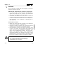
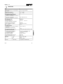
3
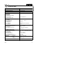
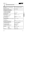
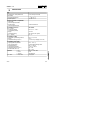
Technische Daten
Typ
Schutzart (nach EN60529/DIN 40050) IP 65 (kompl. montiert)
Umgebungstemperatur - 5
o
bis + 50
o
C
Lagertemperatur -30
o
bis + 70
o
C
Elektromagnetische
Verträglicheit
• Störfestigkeit
geprüft nach EN 50082-2
• Störaussendung
geprüft nach EN 55011
Grenzwertklasse B
Anschluß AS-i-Bus
AS-i + (braun)
• Spannungsbereich
(verpolungssicher)
• Restwelligkeit
• Stromaufnahme
AS-i - (hellblau)
AS-i-BUS
DC 26,5 V ... 31,6 V
20 mVss
max. 85 mA (incl. Sensoren)
DC 0 V
Anschluß 24 VDC
• Nennwert (verpolungssicher)
• Restwelligkeit
• Stromaufnahme (bei 24 V)
DC 24 V (± 10%)
4 Vss
ca. 200 mA pro Ausgang
(max. 5 W)
Anschluß Sensoren (pnp)
• Eingangsspannungsbereich
(plusschaltend)
• Stromaufnahme
• Logikpegel EIN/AUS
• Stromaufnahme (bei 24 V)
• Ansprechverzögerung (bei 24 V)
DC 0...30 V, nicht dauerkurzschluß-
fest
max. 2 x 30 mA
≥ 12,5 V / ≤ 3,5 V
typ. 9 mA
typ. 0,1 ms
Materialien: • Gehäuse
• Kabel
• Schrauben
PA6.6 - GF30, NBR
PUR
Stahl verzinkt
AS-i-Daten: • ID-/IO-Code siehe Typenschild
Deutsch
ASI-M..-...-Z
9801b 5

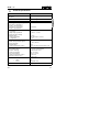
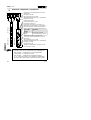
4
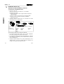
Adressierung von AS-i-Slaves
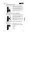
4.1 Anschließen des AS-i-Adressiergeräts
Empfehlung: Verwenden Sie das Festo-Adressiergerät
ASI-PRG-ADR, Teile-Nr. 18959 mit Adapterkabel Teile-
Nr. 18960 (oder Siemens PSG)
4.2 AS-i-Adresse zuweisen/ändern
Vor dem Anschließen eines AS-i-Slaves an den Bus:
Weisen Sie jedem AS-i-Slave eine noch nicht belegte AS-i-
Adresse zu. Stellen Sie Ihre gewünschte Adresse mit dem AS-i-
Adressiergerät ein. Zulässiger Adreßbereich: 1...31.
Anmerkungen:
•• Werkseinstellung der Kombidose: Adresse 00
•• ID-Code und IO-Code: siehe Typenschild der Kombidose
•• Eine Parametrierung des AS-i-Slaves ist nicht erforderlich
Deutsch
ASI-M..-...-Z
6
9801b

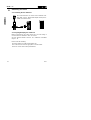
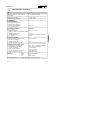
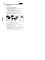
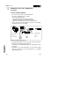
4.3 Adreßbelegung innerhalb der AS-i-Kombidose
ID-Code: F
H
IO-Code: 8
H
IO-Code: B
H
,
D0 = OUT-1
D1 = OUT-2
D2 = OUT-3
D3 = OUT-4
D0 = OUT-1
D1 = OUT-2*)
D2 = IN-1
D3 = IN-2
*) ungenutzt bei Type ..-2E1A-
ASI-Mx-4A-Z
ASI-Mx-2E2A-Z
ASI-Mx-2E1A-Z
OUT -3
OU T - 2
OU T -4
OU T - 1
X + 1
OUT-1
X
OUT-1
OUT-2
Deutsch
ASI-M..-...-Z
9801b 7

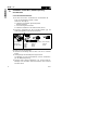
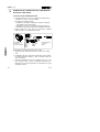
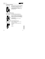
5
Installation von AS-i-Bus, Betriebsspannung
und Sensoren
5.1 Festo-Installationszubehör
•• AS-i-Bus und 24 VDC: Verwenden Sie ausschließlich die
Festo AS-i-Kabeldosen Teile-Nr. 18785.
Gehen Sie wie folgt vor:
1. Kabeldose anschließen gemäß separater
Kurzbeschreibung.
2. AS-i-Kabel zugfrei ausrichten.
3. Kabeldose aufstecken und festschrauben (IP 65).
•• Sensoren: Verwenden Sie das Festo-DUO-Kabel (ggf. mit
Verlängerungskabel) oder den DUO-Stecker.
AS-i-Kabeldose,
ASI-SD-FK,
Teile-Nr. 18785
DUO-Kabel Verlängerungskabel DUO-Stecker
Teile-Nr. Teile-Nr. Teile-Nr.
18685 18684 18779
18687 18686
18688
Beachten Sie bei Stichleitungen:
•• maximale Gesamtlänge des AS-i-Bus: 100 m incl. Stichlei-
tungen
•• Leitungslänge des Betriebsspannungsanschluß:
ist abhängig von der Stromaufnahme und den Schwankun-
gen der Betriebsspannung
•• Abschluß eines offenen Kabelendes: z. B. mit der Festo-Ka-
belkappe. Sie vermeiden damit Kriechströme und erreichen
Schutzart IP 65.
Deutsch
ASI-M..-...-Z
8
9801b

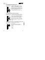
5.2 Anschließen des AS-i-Bus
Pin-Belegung der
AS-i-Schnittstelle:
Anschluß über Festo AS-i-Kabeldose mit gelbem
AS-i-Flachkabel (verpolungsgeschützt durch
mechanische Codierung). Verwenden Sie
ausschließlich ein AS-i-Netzgerät mit sicherer
Trennung (Kleinspannung nach PELV) nach IEC-64
(z. B. AS-i-Kombinetzteil Teile-Nr. 18949).
Stromaufnahme ca. 25 mA + Stromaufnahme
Sensoren (max. 60 mA).
AS-i +
(braun)
AS-i -
(hellblau)
5.3 Anschließen der Betriebsspannung
Pin-Belegung der
24 VDC-Schnittstelle:
Versorgen Sie die Ventile immer getrennt mit
24 V-Betriebsspannung. Eine Spannungs-
versorgung über den AS-i-Bus ist nicht möglich.
Verwenden Sie ein Netzgerät mit sicherer
Trennung (Kleinspannung nach PELV ) nach
IEC-64 (z. B. Festo AS-i-Kombinetzteil Teile-
Nr.18949). Anschluß über Festo AS-i-Kabeldose
mit schwarzem Flachkabel.
Stromaufnahme ca. 200 mA pro Ausgang
(max. 5 W pro Ausgang).
+ 24 V
(braun)
0 V
(hellblau)
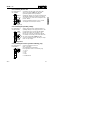
5.4 Anschließen der Sensoren (plus-schaltend, pnp)
Pin-Belegung der
M12-Schnittstelle:
Stromaufnahme der Sensoren (max. 2x30 mA):
siehe Herstellerangaben
Pin-Belegung des Sensoranschlusses (pnp):
1 = + 24 V
2 = IN-2
3 = OV
4 = IN-1
5 = Erde
24 VDC
Deutsch
ASI-M..-...-Z
9801b 9

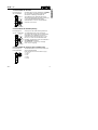
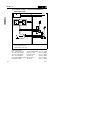
5.5 Anschlußbeispiel Kombidose mit/ohne NOT-AUS
AS-i-Master
Festo-Kombinetzteil
NOT-AUS-Relais
Festo-Zubehör:
AS-i-Kombinetzteil ASI-CNT-115/230 VAC Teile-Nr. 18949
AS-i-Flachkabel (gelb) KASI-1.5-Y-100 Teile-Nr. 18940
AS-i-Flachkabel (schwarz) KASI-1.5-Z-100 Teile-Nr. 18941
AS-i-Kabelverteiler ASI-KVT-FK Teile-Nr. 18786
AS-i-Kabelverteiler (symm.) ASI-KVT-FK-S Teile-Nr. 18797
Bezeichnungsschilder IBS 6x10 Teile-Nr. 18576
ASI +
ASI -
AS-i -
AS-i +
Deutsch
ASI-M..-...-Z
10
9801b

1 General instructions
•• Read this brief description through completely.
Then start the actual fitting.
Correct use of AS-i products
•• AS-i products are designed for use exclusively in bus sys-
tems as agreed in the AS-i specifications. Use in any other
way is not in accordance with these specifications.
•• AS-i bus systems and AS-i combi-sockets may only be in-
stalled by qualified personnel trained for this purpose.
•• Detailed information on the concept and addressing of your
AS-i bus system can be found in the manual for the AS-i
master.
Before commissioning
•• Switch off the power supply before connecting or disconnect-
ing plugs (otherwise functional damage may occur).
•• Only commision combi-sockets which are completely fitted
and connected.
•• Recommendation on symmetrizing/earthing.
The AS-i circuits of the AS-i combi-sockets have been de-
signed so as to be suitable for industrial environments with-
out the need for additional earthing. However, you can only
achieve the EMC values specified in the EU guidelines by
connecting an additional earth/ground cable to the M3
earth/ground screw. This also improves the symmetrizing of
the circuit and increases its stability.
••
If the AS-i master fails during operation, the outputs remain
set.
••
If the AS-i voltage of a slave is cut, the outputs are reset.
English
ASI-M..-...-Z
9801b 11

2
Connecting and display elements
Socket (design/arrangement of contacts
depends on order)
Yellow LED for solenoid coil
Fastening screw (max. 0.5 Nm)
Designation label (e.g. for address)
Numbering of output
Numbering of inputs
Sensor plug M12 for 2 sensors
Earth/ground connection M3
Operating voltage connection 24 V DC
(additional supply, only ...-Z-types, valves can
then be switched off during EMERGENCY
STOP. No power supply via AS-i bus)
BUS LED
(green)
Meaning
On
Off
AS-i voltage applied
No AS-i voltage on bus
AS-i bus connection (AS-i plug)
Socket (design/arrangement of contacts as ordered)
Fastening screw (max. 0.5 Nm)
Designation label (e.g. for address)
Yellow LED for solenoid coil
Numbering of output
Type plate of combi-socket
(with AS-i IO code and ID code)
PLEASE NOTE
The combi-sockets have different contact arrangements:
••
type ASI-MV-...: contact arrangement DIN 43650,
design B (e.g. Festo V-coils)
••
type ASI-MF-...: contact arrangement as per industrial
standard (e.g. Festo F-coils). This contact arrangement
can be turned 180° in order to simplify fitting.
ASI-MV-2E2A-Z
ASI-MV-2E1A-Z ASI-MV-4A-Z
English
ASI-M..-...-Z
12
9801b

3
Technical specifications
Type
Protection class (as per EN 60529/
DIN 40050)
IP 65 (fitted completely)
Ambient temperature - 5
o
to + 50
o
C
Storage temperature -30
o
to + 70
o
C
Electromagnetic compatibility
• Resistance to interference
tested as per EN 50082-2
• Resistance to suppression
tested as per EN 55011
Limit value B
ASI bus connection
AS-i + (brown)
• Voltage range (protected
against incorrect polarity)
• Residual ripple
• Current consumption
AS-i - (light blue)
AS-i BUS
DC 26.5 V ... 31.6 V
20 mVpp
max. 85 mA (incl. sensors)
DC 0 V
24 V DC connection
• Rated value (protected against
incorrect polarity)
• Residual ripple
• Current consumption (at 24 V)
DC 24 V (± 10 %)
4 Vpp
approx. 200 mA per output (max. 5 W)
Sensor connection (pnp)
• Input voltage range
(positive switching)
• Current consumption
• Logic level ON/OFF
• Current consumption (at 24 V)
• Response delay (at 24 V)
DC 0...30 V, not resistant to
sustained short-circuit
max. 2 x 30 mA
≥ 12.5 V / ≤ 3.5 V
typical 9 mA
typical 0.1 ms
Materials • Housing
• Cable
• Screws
PA6.6 - GF30, NBR
PUR
Zinc-plated steel
AS-i data • ID-/IO-code see type plate
English
ASI-M..-...-Z
9801b 13

4
Addressing AS-i slaves
4.1 Connecting the AS-i addresser
We recommend the use of the Festo addresser ASI-
PRG-ADR, part no. 18959 with adapter cable part no.
18960 (or Siemens PSG).
4.2 Assigning/modifying AS-i addresses
Before connecting an AS-i slave to the bus, you must assign a
non-reserved AS-i address to each AS-i slave.
Set the desired address with the AS-i addresser. Permitted
range 1...31.
Please note the following:
•• factory setting of combi-socket address 00
•• ID code and IO code see type plate on combi-socket
•• the AS-i slave need not be parametrized
English
ASI-M..-...-Z
14
9801b

4.3 Address assignment within the AS-i combi-socket
ID code: F
H
IO code: 8
H
IO code: B
H
D0 = OUT-1
D1 = OUT-2
D2 = OUT-3
D3 = OUT-4
D0 = OUT-1
D1 = OUT-2*)
D2 = IN-1
D3 = IN-2
*) not used with type ..-2E1A-
ASI-Mx-4A-Z
ASI-Mx-2E2A-Z
ASI-Mx-2E1A-Z
OUT -3
OU T - 2
OU T -4
OU T - 1
X + 1
OUT-1
X
OUT-1
OUT-2
English
ASI-M..-...-Z
9801b 15

5
Installing the AS-i bus, operating voltage and sensors
5.1 Festo installation accessories
•• AS-i bus and 24 V DC
Use only the Festo AS-i cable sockets part no. 18785.
Proceed as follows.
1. Connect cable socket according to separate brief
description.
2. Fit the AS-i cable so that it is not stretched.
3. Place the cable socket in position and screw it tight.
(IP 65).
•• Sensors
Use the Festo DUO cable (if necessary with extension
cable) or the DUO plug.
AS-i cable socket,
ASI-SD-FK,
part no. 18785
DUO plug Extension cable DUO plug
part no. part no. part no.
18685 18684 18779
18687 18686
18688
Please note the following if there are branch lines.
•• The maximum total length of the AS-i bus must not exceed
100 m, including branch lines.
•• The length of the operating voltage cable depends on the
current consumption and the fluctuations in the operating
voltage.
•• An open cable end must be fitted with e.g. a Festo cable
cap. You thereby avoid leakage currents and comply with
protection class IP 65.
English
ASI-M..-...-Z
16
9801b

5.2 Connecting the AS-i bus
Pin assignment of
AS-i interface
Connection must be made via the Festo AS-i
cable socket with a yellow AS-i flat cable
(protected against incorrect polarity by
mechanical coding). Use a power exclusively unit
with reliable isolation (low voltage es per PELV)
as per IEC-64 (e.g. Festo AS-i combi-power unit
part no. 18949).
Current consumption approx. 25 mA + current
consumption of sensors (max. 60 mA).
AS-i +
(brown)
AS-i -
(light blue)
5.3 Connecting the operating voltage
Pin assignment of
24 VDC interface
+24 V
(brown)
0 V
(light blue)
Always supply the valves separately with 24 V
operating voltage. Power supply via the AS-i bus
is not possible. Use a power unit with reliable
isolation (low voltage es per PELV) as per
IEC-64 (e.g. Festo AS-i combi-power unit part
no. 18949). Connect the power unit to the Festo
AS-i cable socket with a black flat cable.
Current consumption approx. 200 mA per output
(max. 5 W per output).
5.4 Connecting the sensors (positive switching, pnp)
Pin assignment of
M12 interface
Current consumption of sensors
(max. 2 x 30 mA):
see manufacturer specifications.
Pin assignment of sensor connection (pnp):
1 = + 24 V
2 = IN-2
3 = OV
4 = IN-1
5 = Earth/Ground
24 VDC
English
ASI-M..-...-Z
9801b 17

5.5 Connection example – combi-socket with/without
EMERGENCY STOP
AS-i master
Festo combi power unit
EMERGENCY STOP relay
Festo accessories:
AS-i combi-power unit ASI-CNT-115/230VAC part no. 18949
AS-i flat cable (yellow) KASI-1.5-Y-100 part no. 18940
AS-i flat cable (black) KASI-1.5-Z-100 part no. 18941
AS-i cable distributor ASI-KVT-FK part no. 18786
AS-i cable distributor (symm.) ASI-KVT-FK-S part no. 18797
Designation labels IBS 6x10 part no. 18576
ASI +
ASI -
AS-i -
AS-i +
English
ASI-M..-...-Z
18
9801b

1
Instrucciones generales
• Léase completamente esta breve descripción.
A continuación, ponga en marcha el montaje actual.
Uso correcto de los productos AS-i
• Los productos AS-i están diseñados para ser utilizados ex-
clusivamente en sistemas de bus, tal como está acordado
en las especificaciones AS-i. Cualquier otra utilización no
cumplirá con estas especificaciones.
• Los sistemas de bus AS-i y los zócalos AS-i combi, debe ser
instalados por personal cualificado y con formación específica.
• En el manual del master AS-i puede hallar información detallada
sobre el concepto y el direccionamiento del sistema de bus AS-i.
Antes de la puesta a punto
• Corte la tensión de alimentación antes de conectar y desconectar
clavijas (de lo contrario pueden producirse daños funcionales).
• Ponga en marcha los zócalos combi, sólo cuando estén
completamente montados y conectados.
• Recomendación sobre simetrización/puesta a tierra. Los cir-
cuitos AS-i de los zócalos combi AS-i han sido diseñados
para funcionar en entornos industriales sin necesidad de un
tierra adicional. Sin embargo, sólo es posible alcanzar los
valores EMC especificados por las directivas de la CE
conectando un cable de masa/tierra adicional al tornillo de
masa/tierra M3. Esto mejora también la simetrización del cir-
cuito e incrementa su estabilidad.
•
Si el master AS-i falla durante el funcionamiento, las
salidas permanecen activas.
•
Si se corta la tensión AS-i a un slave, las salidas se
desactivan.
Español
ASI-M..-...-Z
9801b 19

2
Elementos de conexión y visualización
Zócalo (diseño/disposición de contactos
según se haya pedido)
LED amarillo para las bobinas
Tornillo de fijación (máx. 0,5 Nm)
Campo de rotulación (p. ej. para direcciones)
Numeración de salidas
Numeración de entradas
Clavija para sensor M12 para 2 sensores
Conexión tierra/masa M3
Conexión de alimentación 24 V DC (alimentación
adicional, sólo tipos...-Z, entonces pueden desco-
nectarse las válvulas en un PARO DE EMERGEN-
CIA. No hay alimentación a través del bus AS-i)
BUS LED
(verde)
Significado
Luce
No luce
Tensión AS-i aplicada
No hay tensión AS-i en el bus
Conexión al bus AS-i (clavija AS-i)
Zócalo (diseño/disposición de los contactos
según se haya pedido)
Tornillo de fijación (máx. 0,5 Nm)
Campo de rotulación (p. ej. para direcciones)
LED amarillo por bobina
Numeración de salidas
Placa de tipo de zócalo combi
(con código AS-i IO e ID)
POR FAVOR, OBSERVAR:
Los zócalos combi tiene una disposición de contactos diferente
•
tipo ASI-MV-...: disposición de contactos DIN 43650,
diseño B (p. ej. Bobinas V de Festo)
•
tipo ASI-MF-...: disposición de contactos según estándar
industrial (p. ej. Bobinas F de Festo). Esta disposición
puede girar 180º para simplificar el montaje.
ASI-MV-2E2A-Z
ASI-MV-2E1A-Z ASI-MV-4A-Z
Español
ASI-M..-...-Z
20
9801b
Sidan laddas...
Sidan laddas...
Sidan laddas...
Sidan laddas...
Sidan laddas...
Sidan laddas...
Sidan laddas...
Sidan laddas...
Sidan laddas...
Sidan laddas...
Sidan laddas...
Sidan laddas...
Sidan laddas...
Sidan laddas...
Sidan laddas...
Sidan laddas...
Sidan laddas...
Sidan laddas...
Sidan laddas...
Sidan laddas...
Sidan laddas...
Sidan laddas...
Sidan laddas...
Sidan laddas...
Sidan laddas...
Sidan laddas...
Sidan laddas...
Sidan laddas...
Sidan laddas...
Sidan laddas...
-
 1
1
-
 2
2
-
 3
3
-
 4
4
-
 5
5
-
 6
6
-
 7
7
-
 8
8
-
 9
9
-
 10
10
-
 11
11
-
 12
12
-
 13
13
-
 14
14
-
 15
15
-
 16
16
-
 17
17
-
 18
18
-
 19
19
-
 20
20
-
 21
21
-
 22
22
-
 23
23
-
 24
24
-
 25
25
-
 26
26
-
 27
27
-
 28
28
-
 29
29
-
 30
30
-
 31
31
-
 32
32
-
 33
33
-
 34
34
-
 35
35
-
 36
36
-
 37
37
-
 38
38
-
 39
39
-
 40
40
-
 41
41
-
 42
42
-
 43
43
-
 44
44
-
 45
45
-
 46
46
-
 47
47
-
 48
48
-
 49
49
-
 50
50


Festo ASI-MF-2E1A-Z Brief description
- Typ
- Brief description
- Denna manual är också lämplig för
på andra språk
- italiano: Festo ASI-MF-2E1A-Z
- español: Festo ASI-MF-2E1A-Z
- Deutsch: Festo ASI-MF-2E1A-Z
- français: Festo ASI-MF-2E1A-Z
- English: Festo ASI-MF-2E1A-Z
Relaterade papper
Andra dokument
-
Festool EAA Bruksanvisning
-
DeWalt DE2000 Användarmanual
-
AVENTICS Bus Control CMS, B-Design, PROFIBUS DP Bruksanvisning
-
-
-
-
IFM AC012S Bruksanvisningar