
MS880
Cruise control
Diagnostic manual. . . . . . . . . . . . . . . . . . . . .3
Geschwindigkeitsregler
Diagnose-Handbuch . . . . . . . . . . . . . . . . . . 13
Régulateurs de vitesse
Manuel de diagnostic . . . . . . . . . . . . . . . . .25
Regulador de velocidad
Manual de diagnóstico . . . . . . . . . . . . . . . .36
Regulador de velocidade
Manual de diagnóstico . . . . . . . . . . . . . . . .47
Regolatore di velocità
Manuale di diagnosi . . . . . . . . . . . . . . . . . .58
Snelheidsregelaar
Diagnosehandleiding . . . . . . . . . . . . . . . . .69
Hastighedsregulering
Diagnosehåndbog . . . . . . . . . . . . . . . . . . .80
Farthållare
Diagnos-handbok . . . . . . . . . . . . . . . . . . . .92
Hastighetsregulator
Diagnosehåndbok. . . . . . . . . . . . . . . . . . .102
Vakionopeussäätimet
Diagnoosikäsikirja. . . . . . . . . . . . . . . . . . . 112
Регулятор скорости движения
Инструкция по диагностике . . . . . . . . . . 122
Regulator prędkości
Podręcznik diagnozy . . . . . . . . . . . . . . . . 134
Temp omat
Diagnostická príručka. . . . . . . . . . . . . . . . 145
Regulátor rychlosti
Diagnostická příručka. . . . . . . . . . . . . . . . 155
Sebességszabályozó
Diagnosztikai kézikönyv . . . . . . . . . . . . . . 166
EN
DE
FR
ES
PT
IT
NL
DA
SV
NO
FI
RU
PL
SK
CS
HU
DRIVING SUPPORT
CRUISE CONTROL
MS880-Diag-16s.book Seite 1 Mittwoch, 7. September 2016 1:39 13

MS880-Diag-16s.book Seite 2 Mittwoch, 7. September 2016 1:39 13

EN
MS880 Troubleshooting
3
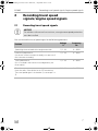
Contents
1 Troubleshooting . . . . . . . . . . . . . . . . . . . . . . . . . . . . . . . . . . . . . . . . . . . . . . . .3
2 Recording travel speed signals/engine speed signals . . . . . . . . . . . . . . . . . .7
2.1 Recording travel speed signals . . . . . . . . . . . . . . . . . . . . . . . . . . . . . . . . . . . .7
2.2 Recording engine speed signals . . . . . . . . . . . . . . . . . . . . . . . . . . . . . . . . . . .8
2.3 Testing the signal . . . . . . . . . . . . . . . . . . . . . . . . . . . . . . . . . . . . . . . . . . . . . . .8
3 Setting the sensitivity . . . . . . . . . . . . . . . . . . . . . . . . . . . . . . . . . . . . . . . . . . . .8
3.1 Starting setup mode . . . . . . . . . . . . . . . . . . . . . . . . . . . . . . . . . . . . . . . . . . . . .8
3.2 Starting automatic mode . . . . . . . . . . . . . . . . . . . . . . . . . . . . . . . . . . . . . . . . .9
3.3 Setting the sensitivity (INIT mode) . . . . . . . . . . . . . . . . . . . . . . . . . . . . . . . . .10
3.4 Setting the control sensitivity manually (GAIN mode). . . . . . . . . . . . . . . . . . 11
3.5 Quitting setup mode . . . . . . . . . . . . . . . . . . . . . . . . . . . . . . . . . . . . . . . . . . .12
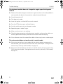
1 Troubleshooting
This section contains a list of possible problems and recommended tests you can
perform to find a solution.
The LED on the electronic module does not light up when you press the
buttons on the control element
➤ Check that the 8-pin compact plug of the electronic module is properly
connected to the control element.
➤ Check the colour code on the connecting plug of the control element and make
sure that the terminals are correctly plugged into the control element.
➤ If the plugs are correctly inserted, check the power supply and earth connection
of the electronic module.
There should be a voltage of +12 V on the orange cable when the ignition is
switched on.
The green cable should have a good earth connection.
MS880-Diag-16s.book Seite 3 Mittwoch, 7. September 2016 1:39 13

EN
Troubleshooting MS880
4
The LED on the electronic module does not light up when you apply the
brake
I
➤ Make sure the LED on the electronic module lights up when you press the
buttons on the control element.
➤ If the LED does not light up, check the power supply and earth connection of the
electronic module.
There should be a voltage of +12 V on the orange cable when the ignition is
switched on.
The green cable should have a good earth connection.
➤ Check the connection of the brown and brown/white cable to the brake light
switch using a voltmeter.
Test the cables with the ignition switched on, because some brake light circuits
are powered via the ignition.
The brown/white cable of the electronic module should be connected to a
brake light switch cable which is connected to either the permanent positive
terminal (terminal 30) or to the ignition (terminal 15).
The brown cable should be connected to the brake light switch cable, which
connects the brake light lamp and the brake light switch. This gives an earth
signal from the brake light lamp supply cable when the brake pedal is not
applied, and a positive signal (+12 V) when the brake pedal is applied.
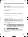
The LED does not flash when an engine speed signal is received (yellow
cable)
This is how to check whether the cruise control is receiving an incorrect engine
speed signal:
➤ Check the engine speed signal using a voltmeter or an oscilloscope.
➤ Make sure the signal is between 6 V and 250 V and the frequency range is
between 6 Hz and 488 Hz.
➤ Check that the yellow cable is not damaged and is properly connected to the
engine speed signal.
NOTE
For reasons of safety, the cruise control does not work when there are
problems with the original brake light circuit.
Therefore, check that the brake lights are working properly.
MS880-Diag-16s.book Seite 4 Mittwoch, 7. September 2016 1:39 13

EN
MS880 Troubleshooting
5
➤ Test the engine speed signal on the electronic module of the cruise control:
– Connect the red cable of the voltmeter or oscilloscope to the yellow cable in
the connecting plug of the electronic module.
– Connect the second cable of the voltmeter or oscilloscope to earth.
➤ Make sure the signal at the electronic module matches that of the vehicle.
If the engine speed signal on the electronic module matches that of the vehicle, the
fault may be due to an incorrect PPM setting. If you chose to record the travel speed
or engine speed signal using the blue cable, the speed controller does not operate
using the engine speed signal (yellow cable).
➤ To change the PPM setting, see chapter “Starting automatic mode” on page 9
The LED does not flash when a travel speed signal is received (blue cable)
This is how to check whether the cruise control is receiving an incorrect engine
speed signal:
➤ Check the travel speed signal using a voltmeter or an oscilloscope.
➤ Make sure the signal is between 1.5 V and 24 V and the frequency range is
between 6Hz and 8.5kHz.
➤ Check that the blue cable is not damaged and is properly connected to the travel
speed signal.
➤ Test the travel speed signal on the electronic module of the cruise control:
– Connect the red cable of the voltmeter or oscilloscope to the blue cable in
the connecting plug of the electronic module.
– Connect the second cable of the voltmeter or oscilloscope to earth.
➤ Make sure the signal at the electronic module matches that of the vehicle.
If the travel speed signal on the electronic module matches that of the vehicle, the
fault may be due to an incorrect PPM setting. If you chose to record the travel speed
or engine speed signal using the yellow cable, the cruise control does not operate
via the travel speed signal (blue cable).
➤ To change the PPM setting, see chapter “Starting automatic mode” on page 9
MS880-Diag-16s.book Seite 5 Mittwoch, 7. September 2016 1:39 13

EN
Troubleshooting MS880
6
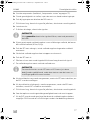
The electronic module does not change the engine speed in diagnosis
mode B
➤ Perform all the other diagnosis mode tests again to make sure that the problem is
not caused by the electrical connections or by the control element.
➤ Switch the ignition off.
➤ Quit diagnosis mode.
➤ Leave the ignition switched off for several seconds.
➤ Press the SET button again and hold it down.
➤ Start the vehicle again to start diagnosis mode.
➤ Repeat diagnosis mode B again.
➤ Make sure the starter is not working.
➤ Check the plug connection to the electronic module, make sure the cables are
correctly positioned and pay attention to the colour code of the plug.
➤ Use a voltmeter to test that none of the cables in the wiring harness are damaged.
The cruise control does not work evenly in control mode
➤ If the cruise control reacts too suddenly or the vehicle speeds up too much in
control mode, you must decrease the GAIN value (see chapter “Setting the con-
trol sensitivity manually (GAIN mode)” on page 11).
➤ If the cruise control operates too slowly in control mode, you must increase the
GAIN value (see chapter “Setting the control sensitivity manually (GAIN mode)”
on page 11).
MS880-Diag-16s.book Seite 6 Mittwoch, 7. September 2016 1:39 13

EN
MS880 Recording travel speed signals/engine speed signals
7
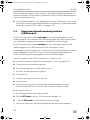
2 Recording travel speed
signals/engine speed signals
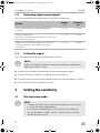
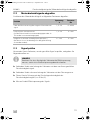
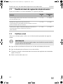
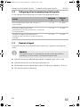
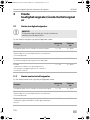
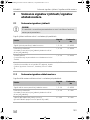
2.1 Recording travel speed signals
A
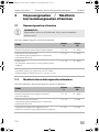
You can record the travel speed signal at the following positions:
NOTICE!
On vehicles with manual transmission, an engine overspeed protection
must be installed.
Position
Voltage
V
Frequency
Hz
Speed signal transmitted via the engine controller 1,5 – 24 6 – 8500
Electronic speed sensor
(on the rear of the instrument assembly or as part set of
the instrument assembly)
1,5 – 24 6 – 8500
Travel speed sensor
(this is installed in the transmission and generally has
three cables)
1,5 – 24 6 – 8500
Car radio
(near the radio, if the vehicle has an ISO connection.
The travel speed signal is in chamber 3, contact pin 1 or
5)
1,5 – 24 6 – 8500
MS880-Diag-16s.book Seite 7 Mittwoch, 7. September 2016 1:39 13

EN
Setting the sensitivity MS880
8
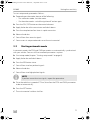
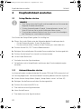
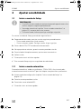
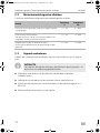
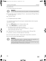
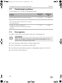
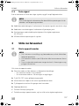
2.2 Recording engine speed signals
You can record the engine speed signal at the following positions:
2.3 Testing the signal
Use a voltmeter to test the signal, proceeding as follows:
I
➤ Connect the red lead of the voltmeter to the selected speed signal.
➤ Connect the black lead of the voltmeter to the vehicle earth.
➤ Drive the vehicle at the activation speed of the cruise control (approx. 40 km/h).
➤ Measure the effective voltage of the signal.
3 Setting the sensitivity
3.1 Starting setup mode
I
Position
Voltage
V
Frequency
Hz
Engine speed signal transmitted via the engine
controller
1,5 – 24 6 – 8500
Electronic speed sensor
(on the rear of the instrument assembly or as part set of
the instrument assembly)
1,5 – 24 6 – 488
Negative terminal end of the ignition coil (terminal 1)
(The yellow cable must be used for this type of
connection)
6 – 250 6 – 488
NOTE
Make sure all digital voltmeters measure the effective voltage when
operating in the AC range.
NOTE
• To begin one of the adjusting and teach modes you must always
carry out the following procedure.
• For automatic mode (page 9), you first have to start the motor.
• For any of the other modes, you first simply have to switch the
ignition off and on again.
MS880-Diag-16s.book Seite 8 Mittwoch, 7. September 2016 1:39 13

EN
MS880 Setting the sensitivity
9
To start setup mode, proceed as follows:
➤ Depending on the mode, do one of the following:
– For automatic mode: start the motor.
– For the other modes: switch the ignition off and on again.
➤ Press the ON/OFF button on the control element.
➤ Apply the brake within one minute and hold it down.
➤ Press the setup button four times in rapid succession.
➤ Release the brake.
✓ You will hear four acoustic signals.
✓ You are now in setup mode and can set the cruise control.
3.2 Starting automatic mode
In automatic mode, the PPM and GAIN parameters are automatically synchronised
with your vehicle. You can still fine-tune both parameters anytime.
➤ Start setup mode (chapter “Starting setup mode” on page 8).
➤ Apply the brake and hold it down.
➤ Press the RES button twice.
✓ You will hear two low-pitched signals.
➤ Release the brake.
✓ You will hear two high-pitched signals.
I
➤ Drive the vehicle at a speed of 70 km/h to allow the PPM and GAIN parameters
to be set automatically.
➤ Press the SET button.
✓ The cruise control switches itself on.
NOTE
If you hear more than two signals, repeat the procedure.
MS880-Diag-16s.book Seite 9 Mittwoch, 7. September 2016 1:39 13

EN
Setting the sensitivity MS880
10
If the cruise control does not take on the speed gently or the save value is not
applied:
➤ Press the SET button again to increase the value or
➤ ... press the RES button to decrease the value.
✓ You will hear a signal each time you press the button.
The current value is indicated by the number of beeps (3 – 14 beeps). The factory
setting is 5 beeps.
➤ Apply the brake to save the set values (PPM and GAIN).
✓ Normally, your cruise control should be ideally preset for your vehicle.
➤ Quit setup mode (chapter “Quitting setup mode” on page 12).
➤ You can now use MagicSpeed MS880.
I
3.3 Setting the sensitivity (INIT mode)
In INIT mode you can set the sensitivity of speed reaction. If the speed regulator
reacts to the speed too slowly you must increase the INIT value. If it reacts too
suddenly to the speed, you must decrease the INIT value.
➤ Start setup mode (chapter “Starting setup mode” on page 8).
➤ To set the sensitivity, apply the brake and hold it down.
➤ With the brake applied, press the RES button three times.
✓ You will hear a low-pitched signal each time you press the button.
➤ Release the brake.
✓ You will hear three high-pitched signals.
I
➤ With the speed controller activated, drive at any speed above the activation
speed (40 km/h).
NOTE
If, during operation, you notice that the vehicle reacts too slowly or too
suddenly, or the speed is not being regulated correctly, you must set the
control sensitivity manually (see chapter “Setting the control sensitivity
manually (GAIN mode)” on page 11).
NOTE
If you do not hear three signals, repeat the procedure.
MS880-Diag-16s.book Seite 10 Mittwoch, 7. September 2016 1:39 13

EN
MS880 Setting the sensitivity
11
➤ Press the SET button until the speed regulator takes on the speed you are driving
at.
➤ Switch off the speed regulator by applying the brake.
➤ Press the SET button.
✓ You will hear a high-pitched signal each time you press the button.
✓ The speed regulator gently takes on the speed.
I
➤ If the reaction to the speed is too slow, press the SET button to increase the INIT
value.
➤ If the reaction to the speed is too sudden, press the RES button to decrease the
INIT value.
✓ You will hear a low-pitched signal each time you press the button.
➤ To save the set sensitivity values, press the brake.
✓ If the INIT value is changed, the speed regulator calculates the optimum GAIN
value and deletes the previous value in the control element.
Normally, no more settings on the control element are required. Therefore, quit
setup mode and test the speed controller in normal operation.
➤ If the speed regulator works too slowly or too suddenly in control mode, you
must make the GAIN setting manually (see chapter “Setting the control sensitivity
manually (GAIN mode)” on page 11).
3.4 Setting the control sensitivity manually
(GAIN mode)
The GAIN value must be increased if the vehicle slows down when the cruise
control is activated or if it reacts too slowly, for example excess loss of speed driving
uphill or excess acceleration driving downhill.
The GAIN value must be decreased if the vehicle speeds up when the cruise control
is activated or if it works too suddenly.
Example: You set a speed of 70 km/h and the vehicle's speed fluctuates between
65 km/h and 75 km/h during control mode. Normally the GAIN value ensures that
the cruise control operates smoothly in control mode.
NOTE
The normal functions of the SET and RES buttons are disabled in this
mode, which means you can use the buttons to make the settings.
MS880-Diag-16s.book Seite 11 Mittwoch, 7. September 2016 1:39 13

EN
Setting the sensitivity MS880
12
To alter the GAIN value, proceed as follows:
➤ Start setup mode (chapter “Starting setup mode” on page 8).
➤ Apply the brake and hold it down.
➤ With the brake applied, press the RES button four times.
✓ You will hear four low-pitched signals.
➤ Release the brake.
✓ You will hear four acoustic signals.
➤ Start the engine.
➤ Drive the vehicle at any speed above the activation speed (40 km/h) to set the
GAIN value.
➤ Press the SET button.
✓ The cruise control switches itself on.
➤ Press the SET button again to increase the GAIN value or
➤ ... press the RES button to decrease the GAIN value.
✓ You will hear a signal each time you press the button.
➤ To save the set values, apply the brake.
➤ Quit setup mode (chapter “Quitting setup mode” on page 12).
3.5 Quitting setup mode
To quit setup mode, proceed as follows:
➤ Stop the vehicle.
➤ Apply the brake and hold it down.
➤ Press the SET button four times.
✓ You will hear a long signal.
✓ You have now quit setup mode.
MS880-Diag-16s.book Seite 12 Mittwoch, 7. September 2016 1:39 13

DE
MS880 Fehler suchen
13
Inhaltsverzeichnis
1 Fehler suchen . . . . . . . . . . . . . . . . . . . . . . . . . . . . . . . . . . . . . . . . . . . . . . . . .13
2 Geschwindigkeitsignale/Motordrehzahlsignale abgreifen . . . . . . . . . . . . .18
2.1 Geschwindigkeitsignale abgreifen . . . . . . . . . . . . . . . . . . . . . . . . . . . . . . . .18
2.2 Motordrehzahlsignale abgreifen . . . . . . . . . . . . . . . . . . . . . . . . . . . . . . . . . .19
2.3 Signal prüfen . . . . . . . . . . . . . . . . . . . . . . . . . . . . . . . . . . . . . . . . . . . . . . . . . .19
3 Empfindlichkeit einstellen. . . . . . . . . . . . . . . . . . . . . . . . . . . . . . . . . . . . . . . 20
3.1 Setup-Modus starten . . . . . . . . . . . . . . . . . . . . . . . . . . . . . . . . . . . . . . . . . . 20
3.2 Automatikmodus starten. . . . . . . . . . . . . . . . . . . . . . . . . . . . . . . . . . . . . . . . 20
3.3 Empfindlichkeit einstellen (INIT-Modus) . . . . . . . . . . . . . . . . . . . . . . . . . . . 22
3.4 Regelempfindlichkeit manuell einstellen (GAIN-Modus) . . . . . . . . . . . . . . 23
3.5 Setup-Modus verlassen . . . . . . . . . . . . . . . . . . . . . . . . . . . . . . . . . . . . . . . . 24
1 Fehler suchen
In diesem Abschnitt finden Sie eine Liste möglicher Probleme und Prüfungen, die zur
Lösung dieser Probleme empfohlen werden.
Die LED des Elektronikmoduls leuchtet nicht auf, wenn die Tasten des
Bedienelements gedrückt werden
➤ Prüfen Sie, ob der 8-polige Kompaktstecker des Elektronikmoduls
ordnungsgemäß mit dem Bedienelement verbunden ist.
➤ Prüfen Sie die Farbcodierung am Verbindungsstecker des Bedienelements und
vergewissern Sie sich, dass die Klemmen ordnungsgemäß in das Bedienelement
eingesteckt sind.
➤ Wenn die Stecker ordnungsgemäß eingesteckt sind, prüfen Sie die Strom-
versorgung und Masseverbindung des Elektronikmoduls.
An der orangefarbenen Leitung sollte bei eingeschalteter Zündung eine
Spannung von +12 V anliegen.
Die grüne Leitung sollte eine gute Masseverbindung haben.
MS880-Diag-16s.book Seite 13 Mittwoch, 7. September 2016 1:39 13

DE
Fehler suchen MS880
14
Die LED des Elektronikmoduls leuchtet nicht auf, wenn die Bremse
betätigt wird
I
➤ Stellen Sie sicher, dass die LED des Elektronikmoduls aufleuchtet, wenn die
Tasten des Bedienelements gedrückt werden.
➤ Wenn die LED nicht aufleuchtet, prüfen Sie die Stromversorgung und
Masseverbindung des Elektronikmoduls.
An der orangefarbenen Leitung sollte bei eingeschalteter Zündung eine
Spannung von +12 V anliegen.
Die grüne Leitung sollte eine gute Masseverbindung haben.
➤ Prüfen Sie mit einem Voltmeter die Verbindungen der braunen und der
braun/weißen Leitung zum Bremslichtschalter.
Testen Sie die Leitungen bei eingeschalteter Zündung, da einige Brems-
lichtstromkreise eine Einspeisung über die Zündung haben.
Die braun/weiße Leitung des Elektronikmoduls sollte mit einer Leitung des
Bremslichtschalters verbunden sein, die entweder mit Dauerplus (Klemme 30)
oder mit der Zündung (Klemme 15) verbunden ist.
Die braune Leitung sollte mit der Leitung des Bremslichtschalters verbunden
sein, die die Verbindung zwischen Bremslichtlampe und Bremslichtschalter
bildet. Dadurch ergibt sich ein Massesignal aus der Zuleitung zur Bremslicht-
lampe, wenn das Bremspedal nicht betätigt ist, und ein Plussignal (+12 V),
wenn das Bremspedal betätigt wird.
HINWEIS
Aus Sicherheitsgründen funktioniert der Geschwindigkeitsregler nicht,
wenn Probleme im Original-Bremslichtstromkreis des Fahrzeuges vor-
liegen.
Testen Sie deshalb zuerst die Bremsleuchten auf ordnungsgemäße
Funktion.
MS880-Diag-16s.book Seite 14 Mittwoch, 7. September 2016 1:39 13

DE
MS880 Fehler suchen
15
Die LED blinkt nicht bei Eingang eines Motordrehzahlsignals
(gelbe Leitung)
Prüfen Sie wie folgt, ob der Geschwindigkeitsregler ein falsches Drehzahlmesser-
signal erhält:
➤ Prüfen Sie das Motordrehzahlsignal mit einem Voltmeter oder Oszilloskop.
➤ Stellen Sie sicher, dass das Signal zwischen 6 V und 250 V liegt und der
Frequenzbereich zwischen 6 Hz und 488 Hz liegt.
➤ Prüfen Sie, ob die gelbe Leitung unbeschädigt und ordnungsgemäß mit dem
Motordrehzahlsignal verbunden ist.
➤ Testen Sie das Motordrehzahlsignal am Elektronikmodul des Geschwindigkeits-
reglers:
– Schließen Sie die rote Leitung des Voltmeters oder Oszilloskops an die gelbe
Leitung im Verbindungsstecker des Elektronikmoduls an.
– Schließen Sie die zweite Leitung des Voltmeters oder Oszilloskops an Masse
an.
➤ Stellen Sie sicher, dass das Signal am Elektronikmodul mit dem Fahrzeugsignal
übereinstimmt.
Wenn das Motordrehzahlsignal am Elektronikmodul mit dem Fahrzeugsignal über-
einstimmt, kann eine falsche PPM-Einstellung den Fehler verursachen. Wenn die
Erfassung des Geschwindigkeitssignals bzw. Drehzahlsignals über die blaue Leitung
gewählt wurde, arbeitet der Geschwindigkeitsregler nicht über das Motordrehzahl-
signal (gelbe Leitung).
➤ Ändern Sie die PPM-Einstellung, siehe Kapitel „Automatikmodus starten“ auf
Seite 20.
MS880-Diag-16s.book Seite 15 Mittwoch, 7. September 2016 1:39 13

DE
Fehler suchen MS880
16
Die LED blinkt nicht bei Eingang eines Geschwindigkeitssignals
(blaue Leitung)
Prüfen Sie wie folgt, ob der Geschwindigkeitsregler ein falsches Geschwindigkeits-
signal erhält:
➤ Prüfen Sie das Geschwindigkeitssignal mit einem Voltmeter oder Oszilloskop.
➤ Stellen Sie sicher, dass das Signal zwischen 1,5 V und 24 V liegt und der
Frequenzbereich zwischen 6 Hz und 8,5 kHz liegt.
➤ Prüfen Sie, ob die blaue Leitung unbeschädigt und ordnungsgemäß mit dem
Geschwindigkeitssignal verbunden ist.
➤ Testen Sie das Geschwindigkeitssignal am Elektronikmodul des
Geschwindigkeitsreglers:
– Schließen Sie die rote Leitung des Voltmeters oder Oszilloskops an die blaue
Leitung im Verbindungsstecker des Elektronikmoduls an.
– Schließen Sie die zweite Leitung des Voltmeters oder Oszilloskops an Masse
an.
➤ Stellen Sie sicher, dass das Signal am Elektronikmodul mit dem Fahrzeugsignal
übereinstimmt.
Wenn das Geschwindigkeitssignal am Elektronikmodul mit dem Fahrzeugsignal
übereinstimmt, kann eine falsche PPM-Einstellung den Fehler verursachen. Wenn
die Erfassung des Geschwindigkeitssignals bzw. Drehzahlsignals über die gelbe
Leitung gewählt wurde, arbeitet der Geschwindigkeitsregler nicht über das
Geschwindigkeitssignal (blaue Leitung).
➤ Ändern Sie die PPM-Einstellung, siehe Kapitel „Automatikmodus starten“ auf
Seite 20.
MS880-Diag-16s.book Seite 16 Mittwoch, 7. September 2016 1:39 13

DE
MS880 Fehler suchen
17
Das Elektronikmodul verändert im Diagnosemodus B nicht die
Motordrehzahl
➤ Führen Sie alle andern Tests des Diagnosemodus erneut durch, um sicher-
zustellen, dass das Problem nicht durch die elektrischen Verbindungen oder
durch das Bedienelement verursacht wird.
➤ Schalten Sie die Zündung aus.
➤ Verlassen Sie den Diagnosemodus.
➤ Lassen Sie die Zündung einige Sekunden ausgeschaltet.
➤ Drücken Sie erneut die SET-Taste und halten Sie diese gedrückt.
➤ Starten Sie das Fahrzeug erneut, um den Diagnosemodus zu starten.
➤ Wiederholen Sie den Diagnosemodus B erneut.
➤ Stellen Sie sicher, dass der Anlasser nicht arbeitet.
➤ Prüfen Sie die Steckerverbindung zum Elektronikmodul und achten Sie auf den
korrekten Sitz der Kabel und die Farbkodierung des Steckers.
➤ Verwenden Sie ein Voltmeter, um zu prüfen, dass kein Kabel des Kabelbaums
beschädigt ist.
Der Geschwindigkeitsregler arbeitet nicht gleichmäßig im Regelbetrieb
➤ Wenn der Geschwindigkeitsregler im Regelbetrieb zu sprunghaft arbeitet oder
die Fahrzeuggeschwindigkeit sich im Regelbetrieb verändert, müssen Sie den
GAIN-Wert verringern (siehe Kapitel „Regelempfindlichkeit manuell einstellen
(GAIN-Modus)“ auf Seite 23).
➤ Wenn der Geschwindigkeitsregler im Regelbetrieb zu träge arbeitet, müssen Sie
den GAIN-Wert erhöhen (siehe Kapitel „Regelempfindlichkeit manuell einstellen
(GAIN-Modus)“ auf Seite 23).
MS880-Diag-16s.book Seite 17 Mittwoch, 7. September 2016 1:39 13

DE
Geschwindigkeitsignale/Motordrehzahlsignale abgreifen MS880
18
2 Geschwindigkeitsignale/Motordrehzahl-
signale abgreifen
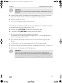
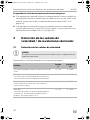
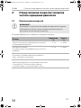
2.1 Geschwindigkeitsignale abgreifen
A
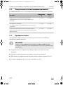
Sie können das Geschwindigkeitssignal an folgenden Positionen abgreifen:
ACHTUNG!
Bei Fahrzeugen mit manuellem Schaltgetriebe müssen Sie einen Motor-
überdrehungsschutz installieren.
Position
Spannung
V
Frequenz
Hz
Über die Motorsteuerung übertragenes
Geschwindigkeitssignal
1,5 – 24 6 – 8500
Elektronischer Drehzahlmesser
(auf der Rückseite der Instrumentenbaugruppe oder als
Teilsatz der Instrumentenbaugruppe)
1,5 – 24 6 – 8500
Geschwindigkeitssensor
(ist am Getriebe installiert und verfügt im Allgemeinen
über drei Leitungen)
1,5 – 24 6 – 8500
Autoradio
(in der Nähe des Radios, falls das Fahrzeug eine
ISO-Verbindung hat. Der Geschwindigkeitsimpuls ist
hierbei in Kammer 3, Kontaktstift 1 oder 5)
1,5 – 24 6 – 8500
MS880-Diag-16s.book Seite 18 Mittwoch, 7. September 2016 1:39 13

DE
MS880 Geschwindigkeitsignale/Motordrehzahlsignale abgreifen
19
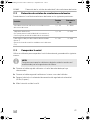
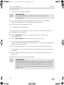
2.2 Motordrehzahlsignale abgreifen
Sie können das Motordrehzahlsignal an folgenden Positionen abgreifen:
2.3 Signal prüfen
Verwenden Sie ein Voltmeter, um das gewählte Signal zu prüfen, und gehen Sie
folgendermaßen vor:
I
➤ Verbinden Sie die rote Leitung des Voltmeters mit dem von Ihnen gewählten
Geschwindigkeitssignal.
➤ Verbinden Sie die schwarze Leitung des Voltmeters mit der Fahrzeugmasse.
➤ Fahren Sie das Fahrzeug mit der Einschaltgeschwindigkeit des
Geschwindigkeitsreglers (ca. 40 km/h).
➤ Messen Sie die Effektivspannung des Signals.
Position
Spannung
V
Frequenz
Hz
Über die Motorsteuerung übertragenes Motordrehzahl-
signal
1,5 – 24 6 – 8500
Elektronischer Drehzahlmesser
(auf der Rückseite der Instrumentenbaugruppe oder als
Teilsatz der Instrumentenbaugruppe)
1,5 – 24 6 – 488
Negative Polseite der Zündungsspule (Klemme 1)
(bei dieser Art von Verbindung muss die gelbe Leitung
verwendet werden)
6 – 250 6 – 488
HINWEIS
Beachten Sie, dass alle digitalen Voltmeter die Effektivspannung
messen, wenn sie im Wechselspannungsbereich arbeiten.
MS880-Diag-16s.book Seite 19 Mittwoch, 7. September 2016 1:39 13

DE
Empfindlichkeit einstellen MS880
20
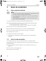
3 Empfindlichkeit einstellen
3.1 Setup-Modus starten
I
Zum Starten des Setup-Modus gehen Sie wie folgt vor:
➤ Führen Sie je nach Modus eine der folgenden beiden Handlungen durch:
– Für den Automatikmodus: Starten Sie den Motor.
– Für die restlichen Modi: Schalten Sie die Zündung aus und wieder ein.
➤ Drücken Sie die ON/OFF-Taste am Bedienelement.
➤ Betätigen Sie innerhalb einer Minute die Bremse und halten Sie diese gedrückt.
➤ Drücken Sie die Setup-Taste viermal kurz hintereinander.
➤ Lassen Sie die Bremse los.
✓ Vier hohe akustische Signale ertönen.
✓ Sie befinden sich im Setup-Modus und können den Geschwindigkeitsregler
einstellen.
3.2 Automatikmodus starten
Im Automatikmodus werden die beiden Parameter PPM und GAIN automatisch auf
Ihr Fahrzeug abgestimmt. Sie können beide Parameter jederzeit noch fein anpassen.
➤ Starten Sie den Setup-Modus (Kapitel „Setup-Modus starten“ auf Seite 20).
➤ Betätigen Sie die Bremse und halten Sie diese gedrückt.
➤ Drücken Sie zweimal die RES-Taste.
✓ Zwei tiefe akustische Signale ertönen.
➤ Lösen Sie die Bremse.
✓ Zwei hohe akustische Signale ertönen.
HINWEIS
• Zum Starten eines der Einstell- und Lernmodi müssen Sie immer die
folgende Prozedur durchführen.
• Für den Automatikmodus (Kapitel „Automatikmodus starten“ auf
Seite 20) müssen Sie im ersten Schritt den Motor starten.
• Für einen der anderen Modi müssen Sie im ersten Schritt lediglich
die Zündung aus- und wieder einschalten.
MS880-Diag-16s.book Seite 20 Mittwoch, 7. September 2016 1:39 13
Sidan laddas...
Sidan laddas...
Sidan laddas...
Sidan laddas...
Sidan laddas...
Sidan laddas...
Sidan laddas...
Sidan laddas...
Sidan laddas...
Sidan laddas...
Sidan laddas...
Sidan laddas...
Sidan laddas...
Sidan laddas...
Sidan laddas...
Sidan laddas...
Sidan laddas...
Sidan laddas...
Sidan laddas...
Sidan laddas...
Sidan laddas...
Sidan laddas...
Sidan laddas...
Sidan laddas...
Sidan laddas...
Sidan laddas...
Sidan laddas...
Sidan laddas...
Sidan laddas...
Sidan laddas...
Sidan laddas...
Sidan laddas...
Sidan laddas...
Sidan laddas...
Sidan laddas...
Sidan laddas...
Sidan laddas...
Sidan laddas...
Sidan laddas...
Sidan laddas...
Sidan laddas...
Sidan laddas...
Sidan laddas...
Sidan laddas...
Sidan laddas...
Sidan laddas...
Sidan laddas...
Sidan laddas...
Sidan laddas...
Sidan laddas...
Sidan laddas...
Sidan laddas...
Sidan laddas...
Sidan laddas...
Sidan laddas...
Sidan laddas...
Sidan laddas...
Sidan laddas...
Sidan laddas...
Sidan laddas...
Sidan laddas...
Sidan laddas...
Sidan laddas...
Sidan laddas...
Sidan laddas...
Sidan laddas...
Sidan laddas...
Sidan laddas...
Sidan laddas...
Sidan laddas...
Sidan laddas...
Sidan laddas...
Sidan laddas...
Sidan laddas...
Sidan laddas...
Sidan laddas...
Sidan laddas...
Sidan laddas...
Sidan laddas...
Sidan laddas...
Sidan laddas...
Sidan laddas...
Sidan laddas...
Sidan laddas...
Sidan laddas...
Sidan laddas...
Sidan laddas...
Sidan laddas...
Sidan laddas...
Sidan laddas...
Sidan laddas...
Sidan laddas...
Sidan laddas...
Sidan laddas...
Sidan laddas...
Sidan laddas...
Sidan laddas...
Sidan laddas...
Sidan laddas...
Sidan laddas...
Sidan laddas...
Sidan laddas...
Sidan laddas...
Sidan laddas...
Sidan laddas...
Sidan laddas...
Sidan laddas...
Sidan laddas...
Sidan laddas...
Sidan laddas...
Sidan laddas...
Sidan laddas...
Sidan laddas...
Sidan laddas...
Sidan laddas...
Sidan laddas...
Sidan laddas...
Sidan laddas...
Sidan laddas...
Sidan laddas...
Sidan laddas...
Sidan laddas...
Sidan laddas...
Sidan laddas...
Sidan laddas...
Sidan laddas...
Sidan laddas...
Sidan laddas...
Sidan laddas...
Sidan laddas...
Sidan laddas...
Sidan laddas...
Sidan laddas...
Sidan laddas...
Sidan laddas...
Sidan laddas...
Sidan laddas...
Sidan laddas...
Sidan laddas...
Sidan laddas...
Sidan laddas...
Sidan laddas...
Sidan laddas...
Sidan laddas...
Sidan laddas...
Sidan laddas...
Sidan laddas...
Sidan laddas...
Sidan laddas...
Sidan laddas...
Sidan laddas...
Sidan laddas...
Sidan laddas...
Sidan laddas...
Sidan laddas...
Sidan laddas...
-
 1
1
-
 2
2
-
 3
3
-
 4
4
-
 5
5
-
 6
6
-
 7
7
-
 8
8
-
 9
9
-
 10
10
-
 11
11
-
 12
12
-
 13
13
-
 14
14
-
 15
15
-
 16
16
-
 17
17
-
 18
18
-
 19
19
-
 20
20
-
 21
21
-
 22
22
-
 23
23
-
 24
24
-
 25
25
-
 26
26
-
 27
27
-
 28
28
-
 29
29
-
 30
30
-
 31
31
-
 32
32
-
 33
33
-
 34
34
-
 35
35
-
 36
36
-
 37
37
-
 38
38
-
 39
39
-
 40
40
-
 41
41
-
 42
42
-
 43
43
-
 44
44
-
 45
45
-
 46
46
-
 47
47
-
 48
48
-
 49
49
-
 50
50
-
 51
51
-
 52
52
-
 53
53
-
 54
54
-
 55
55
-
 56
56
-
 57
57
-
 58
58
-
 59
59
-
 60
60
-
 61
61
-
 62
62
-
 63
63
-
 64
64
-
 65
65
-
 66
66
-
 67
67
-
 68
68
-
 69
69
-
 70
70
-
 71
71
-
 72
72
-
 73
73
-
 74
74
-
 75
75
-
 76
76
-
 77
77
-
 78
78
-
 79
79
-
 80
80
-
 81
81
-
 82
82
-
 83
83
-
 84
84
-
 85
85
-
 86
86
-
 87
87
-
 88
88
-
 89
89
-
 90
90
-
 91
91
-
 92
92
-
 93
93
-
 94
94
-
 95
95
-
 96
96
-
 97
97
-
 98
98
-
 99
99
-
 100
100
-
 101
101
-
 102
102
-
 103
103
-
 104
104
-
 105
105
-
 106
106
-
 107
107
-
 108
108
-
 109
109
-
 110
110
-
 111
111
-
 112
112
-
 113
113
-
 114
114
-
 115
115
-
 116
116
-
 117
117
-
 118
118
-
 119
119
-
 120
120
-
 121
121
-
 122
122
-
 123
123
-
 124
124
-
 125
125
-
 126
126
-
 127
127
-
 128
128
-
 129
129
-
 130
130
-
 131
131
-
 132
132
-
 133
133
-
 134
134
-
 135
135
-
 136
136
-
 137
137
-
 138
138
-
 139
139
-
 140
140
-
 141
141
-
 142
142
-
 143
143
-
 144
144
-
 145
145
-
 146
146
-
 147
147
-
 148
148
-
 149
149
-
 150
150
-
 151
151
-
 152
152
-
 153
153
-
 154
154
-
 155
155
-
 156
156
-
 157
157
-
 158
158
-
 159
159
-
 160
160
-
 161
161
-
 162
162
-
 163
163
-
 164
164
-
 165
165
-
 166
166
-
 167
167
-
 168
168
-
 169
169
-
 170
170
-
 171
171
-
 172
172
-
 173
173
-
 174
174
-
 175
175
-
 176
176


på andra språk
- italiano: Dometic MS880 Manuale del proprietario
- slovenčina: Dometic MS880 Návod na obsluhu
- español: Dometic MS880 El manual del propietario
- Deutsch: Dometic MS880 Bedienungsanleitung
- português: Dometic MS880 Manual do proprietário
- français: Dometic MS880 Le manuel du propriétaire
- dansk: Dometic MS880 Brugervejledning
Relaterade papper
-
Waeco MS800 Bruksanvisningar
-
-
-
-
-
Dometic MS880 Bruksanvisningar
-
-
-
-