Champion 7500 E2 DF Bruksanvisning
- Kategori
- Kraftgeneratorer
- Typ
- Bruksanvisning
Denna manual är också lämplig för

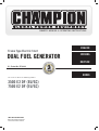
U.S. Patent No. D710,802
OWNER’S MANUAL & OPERATING INSTRUCTIONS
SAVE THESE INSTRUCTIONS
Important Safety Instructions
are included in this manual.
DUAL FUEL GENERATOR
Frame Type Electric Start
This manual covers the following models:
3500 E2 DF (EU/SC)
7500 E2 DF (EU/SC)
T
h
r
e
e
Y
e
a
r
L
i
m
i
t
e
d
W
a
r
r
a
n
t
y
G
a
r
a
n
t
í
a
l
i
m
i
t
a
d
a
d
e
t
r
e
s
a
ñ
o
s
T
h
r
e
e
Y
e
a
r
L
i
m
i
t
e
d
W
a
r
r
a
n
t
y
G
a
r
a
n
t
í
a
l
i
m
i
t
a
d
a
d
e
t
r
e
s
a
ñ
o
s
ENGLISH
SVENSKA
NORSK
DEUTSCH

2
INTRODUCTION
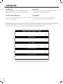
Record the model and serial numbers as well as date and place of purchase for future reference. Have this
information available when ordering parts and when making technical or warranty inquiries.
Champion Power Equipment Support
Model Number
Serial Number
Date of Purchase
Purchase Location
For Oil Type see ‘Add Engine Oil‘ section. For Fuel Type see ‘Add Fuel‘ section.
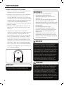
Introduction
Congratulations on purchasing your generator. Please
follow these instructions and maintain it correctly.
Accessories
CPE manufactures and supplies a series of accessories.
See local dealer for more information.
Portable Power Generator
This unit is a petrol engine driven AC generator used for
supply electrical power.
This Booklet
We reserve the right to change, alter or improve the
product and this manual without prior notice.

3
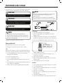
MANUAL CONVENTIONS
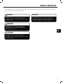
Please familiarize yourself with the following symbols. The safety symbol and key words are safety warnings. Follow all
safety messages to avoid accidents or injury.
CAUTION indicates a potentially hazardous
situation which, if not avoided, may result in minor
or moderate injury.
CAUTION
CAUTION used without the safety alert symbol
indicates a potentially hazardous situation which, if
not avoided, may result in property damage.
CAUTION
DANGER indicates an imminently hazardous
situation which, if not avoided, will result in death
or serious injury.
DANGER
WARNING indicates a potentially hazardous
situation which, if not avoided, could result in
death or serious injury.
WARNING
EN

4
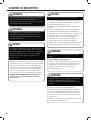
SAFETY RULES
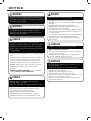
Generator exhaust contains carbon monoxide, a
colourless, odourless, poison gas. Breathing carbon
monoxide will cause nausea, dizziness, fainting or
death. If you start to feel dizzy or weak, get to fresh
air immediately.
Operate generator outdoors only in a well ventilated
area.
DO NOT operate the generator inside any building,
including garages, basements, crawlspaces and
sheds, enclosure or compartment, including the
generator compartment of a recreational vehicle.
DO NOT allow exhaust fumes to enter a confi ned
area through windows, doors, vents or other
openings.
DANGER CARBON MONOXIDE: using a generator
indoors CAN KILL YOU IN MINUTES.
DANGER
Rotating parts can entangle hands, feet, hair,
clothing and/or accessories.
Traumatic amputation or severe laceration can result.
Keep hands and feet away from rotating parts.
Tie up long hair and remove jewelry.
Operate equipment with guards in place.
DO NOT wear loose-fi tting clothing, dangling
drawstrings or items that could become caught.
DANGER
Generator produces powerful voltage.
DO NOT touch bare wires or receptacles.
DO NOT use electrical cords that are worn, damaged
or frayed.
DO NOT operate generator in wet weather.
DO NOT allow children or unqualifi ed persons to
operate or service the generator
Use a ground fault circuit interrupter (GFCI) in damp
areas and areas containing conductive material such
as metal decking.
Use approved transfer equipment to isolate generator
from your electric utility and Notify your utility
company before connecting your generator to your
power system.
DANGER
Sparks can result in fi re or electrical shock.
When servicing the generator:
Disconnect the spark plug wire and place it where it
cannot contact the plug.
DO NOT check for spark with the plug removed.
Use only approved spark plug testers.
WARNING
Running engines produce heat. Severe burns can
occur on contact.
Combustible material can catch fi re on contact.
DO NOT touch hot surfaces.
Avoid contact with hot exhaust gases.
Allow equipment to cool before touching.
Maintain at least 91.4 cm (3 ft.) of clearance on all
sides to ensure adequate cooling.
Maintain at least 1.5 m (5 ft.) of clearance from
combustible materials.
WARNING
Read this manual thoroughly before operating your
generator. Failure to follow instructions could result
in serious injury or death.
WARNING
The engine exhaust from this product contains
chemicals that are known to cause serious health
problems and even death.
WARNING

5
SAFETY RULES
Improper treatment or use of the generator can
damage it, shorten its life and void your warranty.
Use the generator only for intended uses.
Operate only on level surfaces.
DO NOT expose generator to excessive moisture,
dust, or dirt.
DO NOT allow any material to block the cooling slots.
If connected devices overheat, turn them off and
disconnect them from the generator.
DO NOT use the generator if:
– Electrical output is lost
– Equipment sparks, smokes or emits fl ames
–Equipment vibrates excessively
CAUTION
Rapid retraction of the starter cord will pull hand and
arm towards the engine faster than you can let go.
Unintentional startup can result in entanglement,
traumatic amputation or laceration.
Broken bones, fractures, bruises or sprains could result.
When starting engine, pull the starter cord slowly
until resistance is felt and then pull rapidly to avoid
kickback.
DO NOT start or stop the engine with electrical
devices plugged in.
WARNING
Exceeding the generator’s running capacity can
damage the generator and/or electrical devices
connected to it.
DO NOT overload the generator.
Start the generator and allow the engine to stabilize
before connecting electrical loads.
Connect electrical equipment in the off position,
and then turn them on for operation.
Turn electrical equipment off and disconnect before
stopping the generator.
DO NOT tamper with the governed speed.
DO NOT modify the generator in any way.
CAUTION
Medical and Life Support Uses.
In an emergency, call Emergency Services immediately.
NEVER use this product to power life support
devices or life support appliances.
NEVER use this product to power medical devices
or medical appliances.
Inform your electricity provider immediately if you
or anyone in your household depends on electrical
equipment to live.
Inform your electrical provider immediately if a
loss of power would cause you or anyone in your
household to experience a medical emergency.
WARNING
Operation of this equipment may create sparks that
can start fi res around dry vegetation.
A spark arrestor may be required. The operator
should contact local fi re agencies for laws or
regulations relating to fi re prevention requirements.
WARNING EN

6
Petrol and Petrol Vapours:
– PETROL IS HIGHLY FLAMMABLE AND EXPLOSIVE.
– Petrol can cause a fi re or explosion if ignited.
– Petrol is a liquid fuel but it’s vapours can ignite.
– Petrol is a skin irritant and needs to be cleaned up
immediately if spilled on skin or clothes.
– Petrol has a distinctive odour, this will help detect
potential leaks quickly.
– In any petrol fi re, fl ames should not be extinguished
unless by doing so the fuel supply valve can be
turned OFF. This is because if a fi re is extinguished
and a supply of fuel is not turned OFF, then an
explosion hazard could be created.
– Petrol expands or contracts with ambient
temperatures. Never fi ll the petrol tank to full
capacity, as petrol needs room to expand if
temperatures rise.
Liquefi ed Petroleum Gas (LPG):
– LPG IS HIGHLY FLAMMABLE AND EXPLOSIVE.
– Flammable gas under pressure can cause a fi re or
explosion if ignited.
– LPG is heavier than air and can settle in low places
while dissipating.
– LPG has a distinctive odour added to help detect
potential leaks quickly.
– In any petroleum gas fi re, fl ames should not be
extinguished unless by doing so the fuel supply
valve can be turned OFF. This is because if a fi re is
extinguished and a supply of fuel is not turned OFF,
then an explosion hazard could be created.
– When exchanging LPG cylinders, be sure the cylinder
valve is of the same type.
– Always keep the LPG cylinder in an upright position.
– LPG will burn skin if it comes in contact with it.
Keep any and all LPG away from skin at all times.
SAFETY RULES
Fuel Safety
PETROL, PETROL VAPOURS AND LIQUID
PETROLEUM GAS (LPG) ARE HIGHLY
FLAMMABLE AND EXPLOSIVE.
Fire or explosion can cause severe burns or death.
Unintentional startup can result in entanglement,
traumatic amputation or laceration.
DANGER
When adding or removing Petrol:
Turn the generator off and let it cool for at least two
minutes before removing the fuel cap. Loosen the cap
slowly to relieve pressure in the tank.
Only fi ll or drain fuel outdoors in a well-ventilated area.
DO NOT pump petrol directly into the generator at the
petrol station. Use an approved container to transfer the
fuel to the generator.
DO NOT overfi ll the fuel tank.
Always keep fuel away from sparks, open fl ames, pilot
lights, heat and other sources of ignition.
DO NOT light or smoke cigarettes.
When starting the generator:
DO NOT attempt to start a damaged generator.
Make certain that the petrol cap, air fi lter, spark plug,
fuel lines and exhaust system are properly in place.
Allow spilled fuel to evaporate fully before attempting to
start the engine.
Make certain that the generator is resting fi rmly on level
ground.
When operating the generator:
DO NOT move or tip the generator during operation.
DO NOT tip the generator or allow fuel or oil to spill.
When transporting or servicing the generator:
Make certain that the fuel shutoff valve is in the off
position and the fuel tank is empty.
Make certain that a LPG cylinder is not attached to
generator and is securely stowed away.
Disconnect the spark plug wire.
When storing the generator:
Store away from sparks, open fl ames, pilot lights, heat
and other sources of ignition.
Do not store generator, petrol or LPG cylinder near
furnaces, water heaters, or any other appliances that
produce heat or have automatic ignitions.
Never use a petrol container, LPG connector hose,
petrol tank, LPG cylinder or any other fuel item that
is damaged or appears damaged.
WARNING

7
ASSEMBLY
Your generator requires some assembly. This unit ships
from our factory without oil. It must be properly serviced
with fuel and oil before operation.
If you have any questions regarding the assembly of your
generator, call your local dealer. Please have your serial
number and model number available.
Remove the Generator from the Shipping Carton
1. Set the shipping carton on a solid, fl at surface.
2. Remove everything from the carton except the
generator.
3. Carefully cut each corner of the box from top to
bottom. Fold each side fl at on the ground to provide a
surface area to install the wheel kit and support leg.
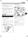
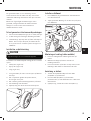
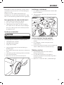
Install the Wheel Kit
You will need the following tools to install the wheels:
• Adjustable wrench (not included)
• Socket wrench (not included)
• Pliers (not included)
1. Before adding fuel and oil, tip the generator on it’s side.
2. Slide the wheel bolt through the fl at washer, bushing
and wheel.
3. Slide the bolt through the mount point on the frame.
4. Fasten securely with the lock nut.
5. Repeat steps 2-4 to attach the second wheel.
Install the Support Leg
1. Attach the support leg to the generator frame with
fl ange bolt and fl ange lock nuts.
2. Tip the generator slowly so that it rests on the
wheels and support leg.
The wheel kit is not intended for over-the-road use.
CAUTION
Connect the Battery
1. Remove the protective cover from the red (+) lead on
the battery.
2. Attach the red (+)lead to the red (+) terminal on the
battery with the fl ange bolt and secure with the
fl ange nut.
3. Repeat steps 1-2 for the black (–) battery lead.
Install the handle (selected models)
1. Place the handle over the mounting channel on the
frame.
2. Secure the handle to the frame using the two handle
bolts.
3. Place the lock nut on the end of each bolt and
fasten securely. DO NOT over tighten the lock nuts.
EN

8
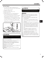
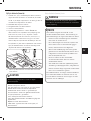
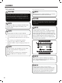
Add Engine Oil
ASSEMBLY
Add Engine Oil Cont’d.
1. Place the generator on a fl at, level surface.
2. Remove oil fi ll cap/dipstick to add oil.
3. Add oil and replace oil fi ll cap/dipstick. DO NOT
OVERFILL.
4. Check engine oil level daily and add as needed.
Full Synthetic 5W-30
Degrees Celsiusº (Outside)
(Outside)
Degrees Fahrenheitº
The engine is equipped with a low oil shut-off and
will stop when the oil level in the crankcase falls
below the threshold level.
CAUTION
DO NOT attempt to crank or start the engine before
it has been properly fi lled with the recommended
type and amount of oil. Damage to the generator as
a result of failure to follow these instructions will
void your warranty.
CAUTION
The generator rotor has a sealed, pre-lubricated ball
bearing that requires no additional lubrication for
the life of the bearing.
NOTE
The recommended oil type is 10W-30 automotive oil.
NOTE
Synthetic oil may be used after the 5 hour initial
break-in period. Using synthetic oil does not
increase the recommended oil change interval.
Full synthetic 5W-30 oil will aid in starting in cold
ambient <5°C (41ºF)
NOTE
We consider the fi rst 5 hours of run time to be
the break-in period for the unit. During the break
in period stay at or below 50% of the running
watt rating and vary the load occasionally to allow
stator windings to heat and cool. Adjusting the
load will also cause engine speed to vary and help
seat piston rings. After the 5 hour break-in period,
change the oil.
NOTE
Once oil has been added, a visual check should show
oil about 1-2 threads from running out of the fi ll hole.
If using the dipstick to check oil level, DO NOT screw
in the dipstick while checking.
NOTE
Weather will affect engine oil and engine
performance. Change the type of engine oil used
based on weather conditions to suit the engine
needs.
NOTE
Check oil often during the break-in period. Refer to the
Maintenance section for recommended service intervals.
NOTE

9
ASSEMBLY
Add Fuel (Petrol) Cont’d.
Our engines work well with 10% or less ethanol
blend fuels. When using blended fuels there are
some issues worth noting:
– Ethanol-petrol blends can absorb more water
than petrol alone.
– These blends can eventually separate, leaving
water or a watery goo in the tank, fuel valve and
carburetor.
– With gravity-fed fuel supplies, this compromised
fuel can be drawn into the carburetor and cause
damage to the engine and/or potential hazards.
– There are only a few suppliers of fuel stabilizer
that are formulated to work with ethanol blend
fuels.
– Any damages or hazards caused by using
improper fuel, improperly stored fuel, and/
or improperly formulated stabilizers, are not
covered by manufacture’s warranty.
It is advisable to always shut off the fuel supply,
run the engine to fuel starvation and drain the tank
when the equipment is not in use for more than 30
days.
NOTE
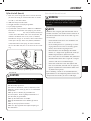
Add Fuel (Petrol)
1. Use clean, fresh, regular unleaded fuel with a
minimum octane rating of 85 and an ethanol content
of less than 10% by volume.
2. DO NOT mix oil with fuel.
3. Clean the area around the fuel cap.
4. Remove the fuel cap.
5. Slowly add fuel to the tank. DO NOT OVERFILL.
Fuel can expand after fi lling. A minimum of
6.4 mm (¼ in.) of space left in the tank is required
for fuel expansion, more than 6.4 mm (¼ in.) is
recommended. Fuel can be forced out of the tank as
a result of expansion if it is overfi lled, and can affect
the stable running condition of the product. When
fi lling the tank, it is recommended to leave enough
space for the fuel to expand.
6. Screw on the fuel cap and wipe away any spilled fuel.
Use regular unleaded petrol with a minimum octane
rating of 85.
Do not mix oil and petrol.
Fill tank to approximately 6.4 mm (¼ in.) below the
top of the tank to allow for fuel expansion.
DO NOT pump petrol directly into the generator at
the petrol station. Use an approved container to
transfer the fuel to the generator.
DO NOT fi ll fuel tank indoors.
DO NOT fi ll fuel tank when the engine is running or hot.
DO NOT overfi ll the fuel tank.
DO NOT light cigarettes or smoke when fi lling the
fuel tank.
CAUTION
Pouring fuel too fast through the fuel screen may
result in blow back of fuel at the operator while fi lling.
WARNING
EN

10
ASSEMBLY
Do not allow children to tamper or play with the
cylinder or hose connections.
CAUTION
Use approved LPG cylinders equipped with an
OPD (overfi lling prevention device) valve. Always
keep the cylinder in a vertical position with the
valve on top and installed at ground level on a fl at
surface Cylinders must not be installed near any
heat source and should not be exposed to sun, rain,
and dust. When transporting and storing, turn off
the cylinder valve and fuel valve, and disconnect
the cylinder. Plug the outlet, usually by a plastic
protective cap, if one is available. Keep cylinders
away from heat and ventilated when in a vehicle.
CAUTION
Connecting LPG Cylinder Cont’d.
Grounding
Your generator must be properly connected to an
appropriate ground to help prevent electric shock.
A ground terminal connected to the frame of the generator
has been provided on the power panel. For remote
grounding, connect of a length of heavy gauge
(12 AWG minimum) copper wire between the generator
ground terminal and a copper rod driven into the ground.
We strongly recommend that you consult with a qualifi ed
electrician to ensure compliance with local electrical codes.
Failure to properly ground the generator can result
in electric shock.
WARNING
– Use only standard 20 or 30 pound capacity LP
tanks with Type 1, right hand Acme threads.
– Verify the requalifi cation date on the tank has
not expired.
– All new cylinders must be purged of air and
moisture prior to fi lling. Used cylinders that have
not been plugged or kept closed must also be
purged.
– The purging process should be done by a LPG
supplier. (Cylinders from an exchange supplier
should have been purged and fi lled properly
already).
– Always position the cylinder so the connection
between the valve and the gas inlet won’t cause
sharp bends or kinks in the hose.
NOTE
Connecting Liquid Petroleum Gas (LPG) Cylinder
1. Make sure the fuel valve on the generator is in the off
position.
2. Attach the LPG hose (included) to the LPG hose
connector on the side of the generator and tighten
with an adjustable wrench.
Important: DO NOT use tape or any other type of
sealant to seal LPG hose connection.
3. Remove the safety plug or cap from the cylinder
valve.
4. Attach the other end of the hose to the LPG
connector on the cylinder and hand tighten.
5. Check all connections for leaks by wetting the fi ttings
with a solution of soap and water. Bubbles which
appear or bubbles which grow indicate that a leak
exists. If a leak exists at a fi tting then turn off the
gas valve at the tank and tighten the fi tting. Turn the
gas back on and recheck the fi tting with the soap
and water solution. If the leak continues or if the leak
is not at a fi tting then do not use the generator and
contact customer service.
If there is a strong smell of gas: Close off the gas
supply at the cylinder. Use soapy water, which will
produce a large bubble at the point of any leak, to
check the hose, and connections on the cylinder valve
and the generator. Do not smoke or light a cigarette,
or check for leaks using a match, open fl ame source
or lighter. Contact a qualifi ed technician to inspect
and repair the LPG system if a leak is found, before
using the generator.
WARNING

11
ASSEMBLY
Generator Location
Never operate the generator inside any building! (See
safety warnings section). In some areas generators must
be registered with the local utility company. Generators
used on construction sites may be subject to local
rules and regulations. Keep on a fl at, level surface.
Generators must have at least 5 ft (1.5m) clearance
from all combustible material. In addition they must
have at least 3 ft (91.4cm) of clearance on all sides to
allow for adequate cooling, maintenance and servicing.
Generators should never be started or operated in ant
location that will not allow for adequate cooling of
the generator and/or the muffl er. Allow generators to
cool before storage or transportation. Do not place the
generator near any vents or intakes. Carefully consider
wind and air currents when placing generator. Failure
to follow the proper safety instructions may void the
manufacturer’s warranty.
Failure to follow proper safety precautions may void
manufacturer’s warranty.
Do not operate or store the generator in rain, snow,
or wet weather.
Using a generator or electrical appliance in wet
conditions, such as rain or snow, or near a pool or
sprinkler system, or when your hands are wet, could
result in electrocution.
WARNING
WARNING
During operation the muffl er and exhaust fumes
produced will become hot. If adequate cooling and
breathing space are not supplied, or if the generator
is blocked or contained, temperatures can become
extremely heated and may lead to fi re.
Surge Protection
Electronic devices, including computers and many
programmable appliances use components that are
designed to operate within a narrow voltage range and
may be affected by momentary voltage fl uctuations.
While there is no way to prevent voltage fl uctuations, you
can take steps to protect sensitive electronic equipment.
1. Install UL1449, CSA-listed, plug-in surge suppressors
on the outlets feeding your sensitive equipment.
Surge suppressors come in single- or multi-outlet
styles. They’re designed to protect against virtually
all short-duration voltage fl uctuations.
Voltage fl uctuation may impair the proper
functioning of sensitive electronic equipment.
CAUTION
Grounding
The generator system ground connects the frame to the
ground terminals on the power panel. The system ground is
connected to the AC neutral wire.
EN

12
OPERATION
The fuel selector switch cover is specifi cally
designed not to slide to either side while a specifi c
fuel has been selected and the valve is in the “ON”
position. Only when the fuel valves are in the “OFF”
position can the cover slide side to side.
NOTE
The fuel selector is locked into place once a
“CLICK” sound is made. Only then can a fuel valve
be turned to the vertical position.
NOTE
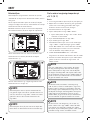
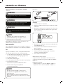
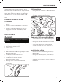
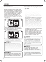
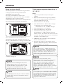
Fuel Selector Switch
The fuel selector switch on the front panel of the
generator is designed specifi cally to choose between the
fuel source desired, Petrol or LPG.
To select a fuel source simply slide the switch cover to
either the right or left, and this will uncover the fuel
valve of the fuel selected.
The LPG fuel valve (A) is to the left of the switch cover.
The petrol fuel valve (B) is to the right of the switch cover.
1A
2B
Once a fuel source has been selected, the user must
turn the fuel valve to the vertical position to open the
fuel valve. (1)
To turn a fuel valve to the off position the valve must be
in the horizontal position. (2)
Starting the Engine in ambient > 15°C (59°F)
Petrol
1. Make certain the generator is on a fl at, level surface.
2. Disconnect all electrical loads from the generator.
Never start or stop the generator with electrical
devices plugged in or turned on.
3. Turn the petrol fuel valve to the “ON” position.
4. Move the choke lever to the “100% CHOKE” detent
position.
a. For restarting a warm engine, move the choke
lever to the “75% CHOKE” detent position.
5. Push the battery switch to the “ON” position.
6. Push the ignition switch to the “ON” position.
7. ELECTRIC START: Press and hold the ignition switch
to the “START” position. Release as the engine begins
to start. If the engine fails to start within fi ve seconds,
release the switch and wait at least ten seconds before
attempting to start the engine again.
8. RECOIL START: Pull the starter cord slowly until
resistance is felt and then pull rapidly.
9. Do not over-choke. As soon as engine starts, gradually
move the choke lever to the “RUN” position over a 2-5
second duration.
Keep choke lever in “Choke” position for only 1
pull of the recoil starter. After fi rst pull, move choke
lever to the “Run” position for up to the next 3
pulls of the recoil starter. Too much choke leads to
sparkplug fouling/engine fl ooding due to the lack of
incoming air. This will cause the engine not to start.
NOTE
For restarts with hot engine in hot ambient > 30°C
(86°F) keep choke lever in “75% Choke” detent
position for only 1 pull of the recoil starter. After
fi rst pull, move choke lever to the “Run” position
for up to the next 3 pulls of the recoil starter. Too
much choke leads to sparkplug fouling/engine
fl ooding due to the lack of incoming air. This will
cause the engine not to start.
NOTE
For petrol starting in in cold ambient < 15°C
(59°F) the choke must be in the 100% “CHOKE”
detent position for both electric and recoil start
procedures. Do not over-choke. As soon as engine
starts, gradually move the choke lever to the “RUN”
position over a 5-20 second duration.
NOTE

13
OPERATION
If the engine starts but does not run make certain that
the generator is on a fl at, level surface. The engine
is equipped with a low oil sensor that will prevent the
engine from running when the oil level falls below a
critical threshold.
NOTE
When the battery switch is in the “ON” position, the
switch will light up if the battery is sending out a
charge. If the switch does not light up while in the “ON”
position, check that the battery connection is still good.
NOTE
The supplied 12V 15AH battery does re-charge while the
engine is running, but it is also recommended that the
battery be fully charged at least once per month.
NOTE
Starting the Engine Cont’d.
If the ignition switch is held down in the “Start” position
longer than 5 seconds it could damage the starter.
CAUTION
LPG
1. Make certain the generator is on a fl at, level surface.
2. Disconnect all electrical loads from the generator.
Never start or stop the generator with electrical
devices plugged in or turned on.
3. Fully open the LPG cylinder fuel knob.
4. Turn the LPG fuel valve to the “ON” position.
5. Push the battery switch to the “ON” position.
6. Push the ignition switch to the “ON” position.
7. ELECTRIC START: Move the choke lever to the “75%
Choke” detent position.
a. For restarting a warm engine, move the choke
lever to the “75% CHOKE” detent position.
8. Press and hold the ignition switch to the “START”
position. Release as the engine begins to start. If the
engine fails to start within fi ve seconds, release the
switch and wait at least ten seconds before attempting
to start the engine again.
9. Do not over-choke. As soon as engine starts, gradually
move the choke lever to the “RUN” position over a 2-5
second duration.
10. RECOIL START: Move the choke lever to the “100%
Choke” detent position.
a. For restarting a warm engine, move the choke
lever to the “100% CHOKE” detent position.
11. PULL-TO-PRIME: Pull the starter cord slowly until
resistance is felt and then pull rapidly. Pull with
“100% Choke” 1-2 times until you feel a few
combustion pulses that indicates that the engine
momentarily started.
12. Move the choke lever to the “RUN” position.
13. Pull the starter cord slowly until resistance is felt and
then pull rapidly.
14. If engine fails to start in 1-pull with choke in the
“RUN”, then move choke to “100% Choke” and
repeat the PULL-TO-PRIME step.
For LPG starting in cold ambient < 15°C (59°F)
Move the choke lever to the “75% Choke” position
for electric starting and “100% Choke” for recoil
start. For electric start, gradually move the choke
lever to the “RUN” position over a 2-10 second
duration. To pull to prime for recoil start Pull with
“100% Choke” 1-3 times until you feel a few
combustion pulses that indicates that the engine
momentarily started.
NOTE
EN

14
OPERATION
Starting the Engine Cont’d. Stopping the Engine Cont’d.
NOTE
Observing frost on LPG containers and regulators
is common during operation and normally is not
an indication of a problem. As LPG vapourizes
and travels from the tank to the generator engine
it expands. The amount of frost that forms can be
affected by the size of the container, the amount of
fuel being used, the humidity of the air and other
operating conditions. In unusual situations this
frost may eventually restrict the fl ow of gas to the
generator resulting in deteriorating performance.
For example, if the tank temperature is reduced
to a very low level then the rate at which the LPG
vaporizes is also reduced and may not provide
suffi cient fuel fl ow to the engine. This is not an
indication of a problem with the generator but
only a problem with the fl ow of gas from the LPG
container. If generator performance seems to be
deteriorating at the same time that ice formation is
observed on tank valve, hose or regulator then some
actions may be taken to eliminate this symptom.
In these rare situations it can be helpful to reduce
or eliminate the cold fuel system effects by doing
one of the following:
– Exchanging fuel tanks to allow the fi rst tank to
warm up, repeating as necessary
– Placing the LPG container at the end of the
generator near the handle, where engine fan air
fl ows out from the generator. This air is slightly
heated by fl owing over the engine. The container
should not be placed in the path of the muffl er
outlet.
– The container can be temporarily warmed by
pouring warm water over the top of the tank.
Connecting Electrical Loads
1. Let the engine stabilize and warm up for a few
minutes after starting
2. Plug in and turn on the desired 120/240 Volt AC
single phase, 50 Hz electrical loads.
– DO NOT connect 3-phase loads to the generator.
– DO NOT connect 60 Hz loads to the generator.
– DO NOT overload the generator.
Connecting a generator to your electric utility company’s
power lines or to another power source may be against
the law. In addition this action, if done incorrectly, could
damage your generator and appliances and could cause
serious injury or even death to you or a utility worker who
may be working on nearby power lines. If you plan to run a
portable electric generator during an outage, please notify
your electric utility company immediately and remember
to plug your appliances directly into the generator. Do not
plug the generator into any electric outlet in your home.
Doing so could create a connection to the utility company
power lines. You are responsible for ensuring that your
generator’s electricity does not feed back into the electric
utility power lines.
If the generator will be connected to a building electrical
system, consult your local utility company or a qualifi ed
electrician. Connections must isolate generator power from
utility power and must comply with all applicable laws and
codes.
NOTE
Stopping the Engine
1. Turn off and unplug all electrical loads. Never start
or stop the generator with electrical devices plugged
in or turned on.
2. Let the generator run at no-load for several minutes
to stabilize internal temperatures of the engine and
generator.
3. Turn the Petrol Fuel Valve to the “OFF” position if
operating by petrol.
4. Turn the LPG cylinder knob to the “CLOSE” or off
position if operating by LPG.
5. Let the engine run until fuel starvation has stopped
the engine. This usually takes a few minutes.
6. Press the ignition switch to the “OFF” position.
7. Turn battery switch to the “Off” Position.
Important: Always ensure that the Fuel Valve and the
Ignition Switch are in the “OFF” position when the
engine is not in use.
When turning off the generator after LPG operation, make
sure the LPG cylinder knob is in the fully closed position.
NOTE
If the engine will not be used for a period of two (2) weeks
or longer, please see the Storage section for proper engine
and fuel storage.
NOTE

15
OPERATION
Do Not Overload Generator
Capacity
Follow these simple steps to calculate the running and
starting watts necessary for your purposes.
1. Select the electrical devices you plan on running at
the same time.
2. Total the running watts of these items. This is
the amount of power you need to keep your items
running.
3. Identify the highest starting wattage of all devices
identifi ed in step 1. Add this number to the number
calculated in step 2. Surge wattage is the extra
burst of power needed to start some electric driven
equipment. Following the steps listed under “Power
Management” will guarantee that only one device will
be starting at a time.
Power Management
Use the following formula to convert voltage and
amperage to watts:
Volts x Amps = Watts
To prolong the life of your generator and attached
devices, follow these steps to add electrical load:
1. Start the generator with no electrical load attached
2. Allow the engine to run for several minutes to stabilize.
3. Plug in and turn on the fi rst item. It is best to attach
the item with the largest load fi rst.
4. Allow the engine to stabilize.
5. Plug in and turn on the next item.
6. Allow the engine to stabilize.
7. Repeat steps 5-6 for each additional item.
Never exceed the specifi ed capacity when adding
loads to the generator.
NOTE
An Important Message About Temperature
Your Champion Power Equipment product is designed
and rated for continuous operation at ambient
temperatures up to 40°C (104°F). When your product is
needed your product may be operated at temperatures
ranging from -l5°C (5°F) to 50°C (122°F) for short
periods. If the product is exposed to temperatures
outside this range during storage, it should be brought
back within this range before operation. In any event,
the product must always be operated outdoors, in a well-
ventilated area and away from doors, windows and other
vents.
EN

16
MAINTENANCE AND STORAGE
The owner/operator is responsible for all periodic
maintenance.
Complete all scheduled maintenance in a timely manner.
Correct any issue before operating the generator.
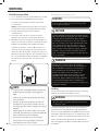
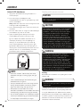
Spark Plugs
1. Remove the spark plug cable from the spark plug.
2. Use a spark socket (not included) to remove the plug.
3. Inspect the electrode on the plug. It must be clean and
not worn to produce the spark required for ignition.
4. Make certain the spark plug gap is 0.7 - 0.8 mm or
(0.028 - 0.031 in.).
5. Refer to the spark plug recommendation chart when
replacing the plug.
6. Carefully thread the plug into the engine.
7. Use a spark plug socket (not included) to fi rmly
install the plug.
8. Attach the spark plug wire to the plug.
Maintenance, replacement, or repair of emission
control devices and systems may be performed
by any non-road engine repair establishment or
individual.
NOTE
Improper maintenance will void your warranty.
WARNING
Oil Cont’d.
0.7 - 0.8 mm
0.028 - 0.031 in.
Engine Maintenance
To prevent accidental starting, remove and ground spark
plug wire before performing any service.
Oil
Change oil when the engine is warm. Refer to the oil
specifi cation to select the proper grade of oil for your
operating environment.
1. Remove the oil drain plug with a 15 mm socket and
extension (not included).
2. Allow the oil to drain completely.
3. Replace the drain plug.
4. Remove oil fi ll cap/dipstick to add oil.
5. Add oil and replace oil fi ll
cap/dipstick. DO NOT OVERFILL.
6. Dispose of used oil at an approved waste
management facility.
Once oil has been added, a visual check should show
oil about 1-2 threads from running out of the fi ll hole.
If using the dipstick to check oil level, DO NOT screw
in the dipstick while checking.
NOTE
Never operate a damaged or defective generator.
WARNING
Tampering with the factory set governor will void
your warranty.
WARNING
Maintenance Valve Clearance
OEM spark plug: NHSP F6RTC
Replacement spark plug: NGK BPR6ES or equivalent
Make certain the *spark plug gap is 0.7 - 0.8 mm or
(0.028 - 0.031 in.).
- Intake: 0.13 - 0.17 mm (0.005 - 0.007 in.)
- Exhaust: 0.18 - 0.22 mm (0.007 - 0.009 in.)
Note: Tech bulletin regarding the valve adjustment
procedure is on www.championpowerequipment.com

17
Air Filter
1. Remove the snap-on cover holding the air fi lter to
the assembly.
2. Remove the foam element.
3. Wash in liquid detergent and water. Squeeze
thoroughly dry in a clean cloth.
4. Saturate in clean engine oil.
5. Squeeze in a clean, absorbent cloth to remove all
excess oil.
6. Place the fi lter in the assembly.
7. Reattach the air fi lter cover and snap in place.
Adjustments
The air-fuel mixture is not adjustable. Tampering with
the governor can damage your generator and your
electrical devices and will void your warranty.
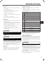
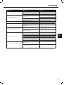
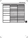
Maintenance Schedule
Follow the service intervals indicated in the following
maintenance schedule.
Service your generator more frequently when operating
in adverse conditions.
Use a damp cloth to clean exterior surfaces of the engine.
Use a soft bristle brush to remove dirt and oil.
Use an air compressor (25 PSI) to clear dirt and debris
from the engine.
Cleaning
DO NOT spray engine with water.
CAUTION
Water can contaminate the fuel system.
Spark Arrester
1. Allow the engine to cool completely before servicing
the spark arrester.
2. Remove the screws holding the cover plate which
retains the end of the spark arrester to the muffl er.
3. Remove the spark arrester screen.
4. Carefully remove the carbon deposits from the spark
arrester screen with a wire brush.
5. Replace the spark arrester if it is damaged.
6. Position the spark arrester in the muffl er and attach
with the screws.
Failure to clean the spark arrester will result in degraded
engine performance.
CAUTION
MAINTENANCE AND STORAGE
*To be performed by knowledgeable, experienced owners or
Champion Power Equipment certifi ed dealers.
Generator Maintenance
Make certain that the generator is kept clean and stored
properly. Only operate the unit on a fl at, level surface in
a clean, dry operating environment. DO NOT expose the
unit to extreme conditions, excessive dust, dirt, moisture
or corrosive vapours.
Use a damp cloth to clean exterior surfaces of the generator.
Use a soft bristle brush to remove dirt and oil.
Use an air compressor (25 PSI) to clear dirt and debris
from the generator.
Inspect all air vents and cooling slots to ensure that they
are clean and unobstructed.
DO NOT use a garden hose to clean the generator.
Water can enter the generator through the cooling
slots and damage the generator windings.
CAUTION
Every 8 hours or daily
Check oil level
Clean around air intake and muffl er
Check hoses for leaks
First 5 hours
Change oil
Every 50 hours or every season
Clean air fi lter
Change oil if operating under heavy load or in hot
environments
Every 100 hours or every season
Change oil
Clean/Adjust spark plug
Check/Adjust valve clearance*
Clean spark arrester
Clean fuel tank and fi lter*
Every 250 hours
Clean combustion chamber*
Every 3 years
Replace fuel line and LPG hose
EN

18
MAINTENANCE AND STORAGE
Storage
The generator should be started at least once every 14
days and allowed to run for at least 20 minutes. For
longer term storage, please follow these guidelines.
Generator Storage
1. Add a properly formulated fuel stabilizer to the tank.
2. Be sure all appliances are disconnected from the
generator.
3. Run the generator for a few minutes so the treated
fuel cycles through the fuel system and carburetor.
4. Turn the fuel valve to the “Off” position.
5. Let the generator run until fuel starvation has
stopped the engine. This usually takes a few minutes.
6. The generator needs to cool completely before
cleaning and storage.
7. Clean the generator according to the maintenance
section.
8. Change the oil.
9. Remove the spark plug and pour about 14.8 mL
(1⁄2 ounce) of oil into the cylinder. Crank the engine
slowly to distribute the oil and lubricate the cylinder.
10. Reattach the spark plug.
11. Store the unit in a clean, dry place out of direct
sunlight.
Generator exhaust contains odourless and
colourless carbon monoxide gas.
To avoid accidental or unintended ignition of your
remote start generator during periods of storage,
the following precautions should be followed:
– When storing the generator for short periods of
time make sure that the Ignition Switch, the Fuel
Valve and the Battery Switch are set in the OFF
position.
– When storing the generator for extended periods
of time make sure that the Ignition Switch, the
Fuel Valve and the Battery Switch are set in the
the the OFF position and the battery leads have
been disconnected from the battery.
DANGER
Generator Battery
This product is equipped with an automatic battery
charging circuit. The battery will receive charging
voltage when the engine is running. The battery will
maintain a proper charge if the unit is used on a
regular basis (about once every two weeks). If it is used
less frequently, the battery should be connected to a
trickle charger (not included) or battery maintainer (not
included) to keep the battery properly charged. If the
battery is not able to start the engine, it can be started
by manually pulling the engine recoil cord. If the battery
voltage is extremely low, the charging circuit may not be
able to re-charge the battery. In this case, the battery
must be connected to a standard automotive style
battery charger for re-charging before it can be used.
Disconnect the Battery
1. Remove the protective cover from the black/negative
battery lead.
2. Disconnect the black/negative lead from the black/
negative terminal on the battery and store the cap
screw (M5x10) and nut (M5).
3. Repeat steps 1-2 for the red/positive battery lead.
4. Store the battery in a cool, dry place.
A Float Charger will maintain the battery condition
over long storage periods.
NOTE
Charge the Battery
For a generator equipped with batteries for electric
starting, proper battery maintenance and storage should
be followed. An automatic battery charger (not included)
with automatic trickle charging capability should be used
to charge the battery. Maximum charging rate should not
exceed 1.5 amps. Follow the instructions included with
the battery charger. The battery should be fully charged
at least once per month.

19
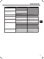
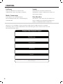
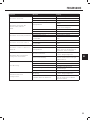
TROUBLESHOOTING
Problem Cause Solution
Generator will not start
No fuel Add fuel
Faulty spark plug Replace spark plug
Unit loaded during start up Remove load from unit
Generator will not start;
Generator starts but runs roughly
Low oil level Fill crankcase to the proper level
Place generator on a fl at, level surface
Choke in the wrong position Adjust choke
Spark plug wire loose Attach wire to spark plug
Generator will not start electrically Generator battery is dead Recharge generator battery
Battery switch is in the “OFF” position Turn battery switch to “ON” position
Generator shuts down during operation
Out of fuel Fill the petrol tank or fi ll LPG cylinder
Low oil level Fill crankcase to the proper level. Place
generator on a fl at, level surface
Generator cannot supply enough power or
overheating
Generator is overloaded Review load and adjust. See “Power
Management”
Insuffi cient ventilation Check for air restriction. Move to a well
ventilated area
No AC output
Cable not properly connected Check all connections
Connected device is defective Replace defective device
Circuit breaker is open Reset circuit breaker
Faulty brush assembly Replace brush assembly (Service Center)
Faulty AVR (auto voltage regulator) Replace AVR (Service Center)
Loose wiring Inspect and tighten wiring connections
Other Contact the help line
Repeated circuit breaker tripping
Overload Review load and adjust. See “Power
Management”
Faulty cords or device Check for damaged, bare or frayed wires.
Replace defective device
EN

20
INTRODUKTION
Notera modell- och serienummer samt datum och inköpsställe för framtida behov. Ha denna information tillgänglig
vid beställning av reservdelar och vid tekniska eller garantiförfrågningar.
Champion Power Equipment support
Modellnummer
Serienummer
Inköpsdatum
Inköpsplats
För oljetyp, se avsnittet “Fyll på olja”. För bränsletyp, se avsnittet “Fyll på bränsle”.
Introduktion
Grattis till att ha köpt denna generator. Vårda och ta
hand om den korrekt.
Tillbehör
CPE tillverkar och tillhandahåller en mängd olika
tillbehör. Se din lokala handlare för mer information.
Portabel strömgenerator
Denna enhet är en bensinmotordriven
växelströmsgenerator som används för att generera
elektrisk ström.
Denna broschyr
Vi förbehåller oss rätten att ändra eller förbättra
produkten eller denna manual utan vidare förvarning.
Sidan laddas...
Sidan laddas...
Sidan laddas...
Sidan laddas...
Sidan laddas...
Sidan laddas...
Sidan laddas...
Sidan laddas...
Sidan laddas...
Sidan laddas...
Sidan laddas...
Sidan laddas...
Sidan laddas...
Sidan laddas...
Sidan laddas...
Sidan laddas...
Sidan laddas...
Sidan laddas...
Sidan laddas...
Sidan laddas...
Sidan laddas...
Sidan laddas...
Sidan laddas...
Sidan laddas...
Sidan laddas...
Sidan laddas...
Sidan laddas...
Sidan laddas...
Sidan laddas...
Sidan laddas...
Sidan laddas...
Sidan laddas...
Sidan laddas...
Sidan laddas...
Sidan laddas...
Sidan laddas...
Sidan laddas...
Sidan laddas...
Sidan laddas...
Sidan laddas...
Sidan laddas...
Sidan laddas...
Sidan laddas...
Sidan laddas...
Sidan laddas...
Sidan laddas...
Sidan laddas...
Sidan laddas...
Sidan laddas...
Sidan laddas...
Sidan laddas...
Sidan laddas...
Sidan laddas...
Sidan laddas...
Sidan laddas...
Sidan laddas...
Sidan laddas...
Sidan laddas...
Sidan laddas...
Sidan laddas...
Sidan laddas...
Sidan laddas...
Sidan laddas...
Sidan laddas...
Sidan laddas...
Sidan laddas...
Sidan laddas...
Sidan laddas...
-
 1
1
-
 2
2
-
 3
3
-
 4
4
-
 5
5
-
 6
6
-
 7
7
-
 8
8
-
 9
9
-
 10
10
-
 11
11
-
 12
12
-
 13
13
-
 14
14
-
 15
15
-
 16
16
-
 17
17
-
 18
18
-
 19
19
-
 20
20
-
 21
21
-
 22
22
-
 23
23
-
 24
24
-
 25
25
-
 26
26
-
 27
27
-
 28
28
-
 29
29
-
 30
30
-
 31
31
-
 32
32
-
 33
33
-
 34
34
-
 35
35
-
 36
36
-
 37
37
-
 38
38
-
 39
39
-
 40
40
-
 41
41
-
 42
42
-
 43
43
-
 44
44
-
 45
45
-
 46
46
-
 47
47
-
 48
48
-
 49
49
-
 50
50
-
 51
51
-
 52
52
-
 53
53
-
 54
54
-
 55
55
-
 56
56
-
 57
57
-
 58
58
-
 59
59
-
 60
60
-
 61
61
-
 62
62
-
 63
63
-
 64
64
-
 65
65
-
 66
66
-
 67
67
-
 68
68
-
 69
69
-
 70
70
-
 71
71
-
 72
72
-
 73
73
-
 74
74
-
 75
75
-
 76
76
-
 77
77
-
 78
78
-
 79
79
-
 80
80
-
 81
81
-
 82
82
-
 83
83
-
 84
84
-
 85
85
-
 86
86
-
 87
87
-
 88
88


Champion 7500 E2 DF Bruksanvisning
- Kategori
- Kraftgeneratorer
- Typ
- Bruksanvisning
- Denna manual är också lämplig för
på andra språk
Relaterade papper
Andra dokument
-
MSW MSW-GP-100 Bruksanvisning
-
-
FXA PD 2500I Användarmanual
-
McCulloch B40 P ELITE Användarmanual
-
Scheppach SG3200x Användarmanual
-
Parkside PSE 2800 B2 Translation Of Original Operation Manual
-
Hyundai 55051 Användarmanual
-
Scheppach 5906212901 Användarmanual
-