
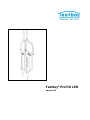
Testboy® Profi III LED
Version 4.5

Testboy® Profi III LED
Bedienungsanleitung
3
Testboy® Profi III LED
Operating instructions
11
Testboy® Profi III LED
Manuel d'utilisation
19
Testboy® Profi III LED
Manual de instrucciones
27
Testboy® Profi III LED
Manual de instruções
35
Testboy® Profi III LED
Manuale utente
43
Testboy® Profi III LED
Bedieningshandleiding
51
Testboy® Profi III LED
Betjeningsvejledning
59
Testboy® Profi III LED
Bruksanvisning
67
Testboy® Profi III LED
Bruksanvisning
75
Testboy® Profi III LED
Käyttöohje
83
Testboy® Profi III LED
Οδηγίες χειρισμού
91
Testboy® Profi III LED
Kullanım kılavuzu
99
Testboy® Profi III LED
Kezelési útmutató
107
Testboy® Profi III LED
Instrukcja obsługi
115
Testboy® Profi III LED
Инструкция по пользованию
123
Testboy® Profi III LED
Návod k obsluze
131
Testboy® Profi III LED
Instrucțiuni de utilizare
139
Testboy® Profi III LED
Návod na obsluhu
147

Inhaltsverzeichnis
Testboy® Profi III LED 3
ENGLISH
DEUTSCH
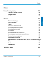
Inhaltsverzeichnis
Sicherheitshinweise 4
Bestimmungsgemäße Verwendung 5
Haftungsausschluss 5
Entsorgung 6
Bedienung 6
Sicherheitshinweise 6
Allgemeines 7
Funktion 7
Selbsttest / Auto Power-Off 7
Gleichspannung prüfen 8
Wechselspannung prüfen 8
Phasenprüfung 8
Drehfeldprüfung (> 200 V AC) 8
Einhandprüfung (z.B. Schuko-Steckdose) 8
Prüfstellenbeleuchtung 8
Durchgangsprüfung 9
Lastzuschaltung / FI/RCD-Auslösetest, PE (Schutzleitertest) 9
Reinigung 9
Wartung 9
Batteriewechsel 9
Technische Daten 10

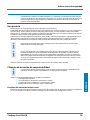
Sicherheitshinweise
4 Testboy® Profi III LED
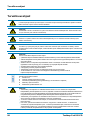
Sicherheitshinweise
WARNUNG
Lesen Sie vor Gebrauch diese Anleitung genau durch. Wenn das Gerät nicht den Herstellerangaben entsprechend
eingesetzt wird, kann der durch das Gerät bereitgestellte Schutz beeinträchtigt werden.
WARNUNG
Gefahrenquellen sind z.B. mechanische Teile, durch die es zu schweren Verletzungen von Personen kommen
kann. Auch die Gefährdung von Gegenständen (z.B. die Beschädigung des Gerätes) besteht.
WARNUNG
Stromschlag kann zum Tod oder zu schweren Verletzungen von Personen führen sowie eine Gefährdung für die
Funktion von Gegenständen (z.B. die Beschädigung des Gerätes) sein.
WARNUNG
Aus Sicherheits- und Zulassungsgründen (CE) ist das eigenmächtige Umbauen und/oder Verändern des Gerätes
nicht gestattet. Um einen sicheren Betrieb mit dem Gerät zu gewährleisten, müssen Sie die Sicherheitshinweise,
Warnvermerke und das Kapitel "Bestimmungsgemäße Verwendung" unbedingt beachten.
WARNUNG
Beachten Sie vor dem Gebrauch des Gerätes bitte folgende Hinweise:
| Vermeiden Sie einen Betrieb des Gerätes in der Nähe von elektrischen Schweißgeräten, Induktionsheizern und
anderen elektromagnetischen Feldern.
| Nach abrupten Temperaturwechseln muss das Gerät vor dem Gebrauch zur Stabilisierung ca. 30 Minuten an die
neue Umgebungstemperatur angepasst werden.
| Bei niedrigeren Temperaturen unter 5 °C kann die Bereitschaft des Spannungsprüfers beeinträchtigt werden.
Bitte sorgen Sie für genügend Stromversorgung, in dem Sie geeignete Batterien verwenden, die auch für den
eingesetzten Temperaturbereich spezifiziert sind!
| Setzen Sie das Gerät nicht längere Zeit hohen Temperaturen aus.
| Vermeiden Sie staubige und feuchte Umgebungsbedingungen.
| Der Spannungsprüfer und das Zubehör sind kein Spielzeug und gehören nicht in Kinderhände!
| In gewerblichen Einrichtungen sind die Unfallverhütungsvorschriften des Verbandes der gewerblichen Berufsge-
nossenschaften für elektrische Anlagen und Betriebsmittel zu beachten.
Bitte beachten Sie die fünf Sicherheitsregeln:
1 Freischalten
2 Gegen Wiedereinschalten sichern
3 Spannungsfreiheit feststellen (Spannungsfreiheit ist 2-polig festzustellen)
4 Erden und kurzschließen
5 Benachbarte unter Spannung stehende Teile abdecken
WARNUNG
| Ein Spannungsprüfer mit relativ niedriger Impedanz wird im Vergleich zum Referenzwert 100 k nicht alle Stör-
spannungen mit einem Ursprungswert oberhalb ELV anzeigen. Bei Kontakt mit den zu prüfenden Anlagenteilen
kann der Spannungsprüfer die Störspannungen durch Entladung vorübergehend bis zu einem Pegel unterhalb
ELV herabsetzen; nach dem Entfernen des Spannungsprüfers wird die Störspannung ihren Ursprungswert aber
wieder annehmen.
| Ein Spannungsprüfer mit relativ hoher innerer Impedanz wird im Vergleich zum Referenzwert 100 k bei vor-
handener Störspannung „Betriebsspannung nicht vorhanden“ nicht eindeutig anzeigen.
| Wenn die Anzeige „Spannung vorhanden“ nicht erscheint, wird dringend empfohlen, vor Aufnahme der Arbeiten
die Erdungseinrichtung einzulegen.
| Wenn die Anzeige „Spannung vorhanden“ bei einem Teil erscheint, der als von der Anlage getrennt gilt, wird
dringend empfohlen, mit zusätzlichen Maßnahmen (z.B.: Verwendung eines geeigneten Spannungsprüfers,

Sicherheitshinweise
Testboy® Profi III LED 5
ENGLISH
DEUTSCH
Sichtprüfung der Trennstelle im elektrischen Netz, usw.) den Zustand „Betriebsspannung nicht vorhanden“ des
zu prüfenden Anlagenteils nachzuweisen und festzustellen, dass die vom Spannungsprüfer angezeigte Span-
nung eine Störspannung ist.
Bestimmungsgemäße Verwendung
Nur für den Einsatz durch Elektrofachkräfte und fachkundiges Personal vorgesehen.
Das Gerät ist nur für die in der Bedienungsanleitung beschriebenen Anwendungen wie Wechselspannungs-, Gleichspannungs- und
Durchgangsprüfungen, Phasen- und Drehfeldtest, bestimmt. Eine andere Verwendung ist unzulässig und kann zu Unfällen oder
Zerstörung des Gerätes führen. Diese Fehlanwendungen führen zu einem sofortigen Erlöschen jeglicher Garantie- und Gewährleis-
tungsansprüche des Bedieners gegenüber dem Hersteller.
Jeder, der dieses Prüfgerät verwendet, sollte entsprechend ausgebildet und mit den besonderen, in einem industriellen Umfeld auf-
tretenden Gefahren bei der Spannungsprüfung, den notwendigen Sicherheitsvorkehrungen und den Verfahren zur Überprüfung der
ordnungsgemäßen Funktion des Gerätes vor und nach jedem Gebrauch vertraut sein.
Um das Gerät vor Beschädigung zu schützen, entfernen Sie bei längerem Nichtgebrauch des Gerätes die Batte-
rien.
Bei Sach- oder Personenschäden, die durch unsachgemäße Handhabung oder Nichtbeachtung der Sicherheits-
hinweise verursacht werden, übernehmen wir keine Haftung. In solchen Fällen erlischt jeglicher Garantiean-
spruch. Ein in einem Dreieck befindliches Ausrufezeichen weist auf Sicherheitshinweise in der Bedienungsanlei-
tung hin. Lesen Sie vor Inbetriebnahme die Anleitung komplett durch. Dieses Gerät ist CE-geprüft und erfüllt so-
mit die erforderlichen Richtlinien.
Rechte vorbehalten, die Spezifikationen ohne vorherige Ankündigung zu ändern © 2017 Testboy GmbH, Deutschland.
Haftungsausschluss
Bei Schäden, die durch Nichtbeachten der Anleitung verursacht werden, erlischt der Garantieanspruch!
Für Folgeschäden, die daraus resultieren, übernehmen wir keine Haftung!
Testboy haftet nicht für Schäden, die aus
| dem Nichtbeachten der Anleitung
| von Testboy nicht freigegebenen Änderungen am Produkt oder
| von Testboy nicht hergestellten oder nicht freigegebenen Ersatzteilen
| Alkohol-, Drogen- oder Medikamenteneinfluss hervorgerufen werden
resultieren.
Richtigkeit der Bedienungsanleitung
Diese Bedienungsanleitung wurde mit großer Sorgfalt erstellt. Für die Richtigkeit und Vollständigkeit der Daten, Abbildungen
und Zeichnungen wird keine Gewähr übernommen. Änderungen, Druckfehler und Irrtümer vorbehalten.

Bedienung
6 Testboy® Profi III LED
Entsorgung
Sehr geehrter Testboy-Kunde, mit dem Erwerb unseres Produktes haben Sie die Möglichkeit, das Gerät nach Ende seines Lebens-
zyklus an geeignete Sammelstellen für Elektroschrott zurückzugeben.
Die WEEE regelt die Rücknahme und das Recycling von Elektroaltgeräten. Hersteller von Elektrogeräten sind dazu
verpflichtet, Elektrogeräte, die verkauft werden, kostenfrei zurückzunehmen und zu recyceln. Elektrogeräte dürfen
dann nicht mehr in die „normalen“ Abfallströme eingebracht werden. Elektrogeräte sind separat zu recyceln und zu
entsorgen. Alle Geräte, die unter diese Richtlinie fallen, sind mit diesem Logo gekennzeichnet.
Entsorgung von gebrauchten Batterien
Sie als Endverbraucher sind gesetzlich (Batteriegesetz) zur Rückgabe aller gebrauchten Batterien und Akkus ver-
pflichtet;
Eine Entsorgung über den Hausmüll ist untersagt!
Schadstoffhaltige Batterien/Akkus sind mit nebenstehenden Symbolen gekennzeichnet, die auf das Verbot der Ent-
sorgung über den Hausmüll hinweisen.
Die Bezeichnungen für das ausschlaggebende Schwermetall sind u.a.:
Cd = Cadmium, Hg = Quecksilber, Pb = Blei, Mn = Mangan, Li = Lithium.
Ihre verbrauchten Batterien/Akkus können Sie unentgeltlich bei den Sammelstellen Ihrer Gemeinde oder überall dort
abgeben, wo Batterien/Akkus verkauft werden!
Qualitätszertifikat
Alle innerhalb der Testboy GmbH durchgeführten, qualitätsrelevanten Tätigkeiten und Prozesse werden permanent durch ein Quali-
tätsmanagementsystem überwacht. Die Testboy GmbH bestätigt weiterhin, dass die während der Kalibrierung verwendeten Prü-
feinrichtungen und Instrumente einer permanenten Prüfmittelüberwachung unterliegen.
Konformitätserklärung
Das Produkt erfüllt die aktuellsten Richtlinien. Nähere Informationen erhalten Sie auf www.testboy.de
Bedienung
Vielen Dank, dass Sie sich für den Testboy® Profi III LED, einen zweipoligen Spannungsprüfer mit LED-Anzeige, entschieden ha-
ben. Es können Gleichspannungen (6 V bis 1400 V) und Wechselspannungen (6 V bis 1000 V) gegen Erde, Polaritäts-, Drehfeld-
richtungs- und Durchgangsprüfungen bis 200 k sowie FI/RCD-Tests durchgeführt werden.
Dank des drehbaren Abstandhalters ist bei Spannungsprüfungen eine Einhandbedienung möglich.
Der Testboy® Profi III LED ist durch die hohe Schutzart (IP65) auch bei rauem Einsatz verwendbar.
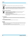
Sicherheitshinweise
Sie haben sich für ein Gerät entschieden, das Ihnen ein hohes Maß an Sicherheit bietet. Um eine gefahrlose und richtige Anwendung si-
cherzustellen, ist es unerlässlich, dass Sie diese Bedienungsanleitung vor dem ersten Gebrauch vollständig durchlesen.

Bedienung
Testboy® Profi III LED 7
ENGLISH
DEUTSCH
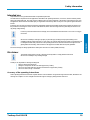
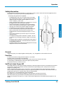
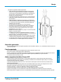
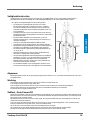
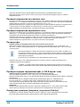
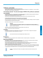
Es gelten folgende Sicherheitsvorkehrungen:
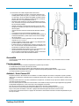
| Der Spannungsprüfer muss kurz vor dem Einsatz auf Funktion überge-
prüft werden (VDE-Vorschrift 0105, Teil 1). Vergewissern Sie sich,
dass die Prüfleitung und das Gerät in einem einwandfreien Zustand
sind. Überprüfen Sie das Gerät an einer bekannten Spannungsquelle,
z.B. 230 V-Steckdose.
| Fällt hierbei die Anzeige einer oder mehrerer Funktionen aus, darf das
Gerät nicht mehr verwendet werden und muss von Fachpersonal über-
prüft werden.
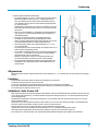
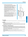
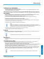
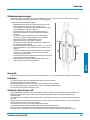
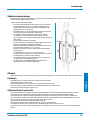
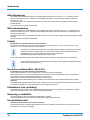
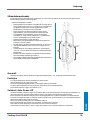
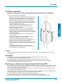
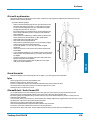
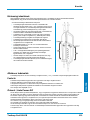
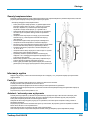
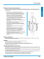
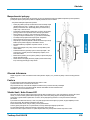
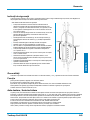
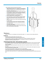
| Gerät nur an den Handgriffen (3) unterhalb der mechanischen Markie-
rung (2) anfassen, vermeiden Sie die Berührung der Prüfspitzen (1)!
(siehe Bilddarstellung)
| Prüfungen auf Spannungsfreiheit nur zweipolig durchführen!
| Das Gerät darf nicht in feuchter Umgebung betrieben werden!
| Nicht mit offenem Batteriefach benutzen! Die Prüfspitzen müssen wäh-
rend eines Batteriewechsels vom Prüfkreis entfernt werden.
| Eine einwandfreie Anzeige ist im Temperaturbereich von -15 °C bis
+45 °C sichergestellt.
| Das Gerät immer trocken und sauber halten. Das Gehäuse darf nur mit
einem feuchten Tuch gereinigt werden.
| Das zusätzlich anzeigende Warnsymbol und Vibration bei Spannungen
> 45 V AC / 110 V DC dienen nur zur Warnung von lebensgefährli-
chen Spannungen, nicht zu Prüfzwecken!
| Batterien sofort wechseln, wenn kurz nach dem Einschalten oder
schon beim Einschalten das Gerät sich sofort wieder abschaltet.
| Die verschiedenen anzeigenden Signale des Spannungsprüfers (ein-
schließlich des ELV-Grenzwertes) dürfen nicht für Messzwecke ver-
wendet werden.
Allgemeines
Spannungen haben Priorität. Liegt keine Spannung an den Prüfspitzen an ( < 6 V ), befindet sich das Gerät im Modus Durchgangs-
prüfung.
Funktion
Zum Einschalten des Gerätes halten Sie einfach die Prüfspitzen kurz aneinander.
Im Stand-by Zustand leuchtet die orange "Rx/"-LED.
Das An- bzw. Abschrauben der Prüfspitzenadapter macht das Prüfen an Steckdosen komfortabler.
Zur sicheren Aufbewahrung befindet sich eine passende Halterung am unverlierbaren Prüfspitzenschutz.
Der nominale Strom In liegt bei maximal 3,5 mA.
Selbsttest / Auto Power-Off
Beim ersten Einschalten, entweder beim Einlegen neuer Batterien oder beim aneinanderhalten der Prüfspitzen wenn das Gerät aus
ist (die "Rx/"-LED leuchtet nicht), des Gerätes leuchten alle optischen Anzeigen (LEDs) auf. Kurz danach wechselt das Gerät in
die Durchgangsprüfung.
Fällt hierbei die Anzeige einer oder mehrerer Funktionen aus, darf das Gerät nicht mehr verwendet werden und muss vom Fach-
personal überprüft werden.
Halten Sie zum Test die Prüfspitzen aneinander, dieses sollte kurz vor und nach der Anwendung erfolgen, um die Betriebsbereit-
schaft des Gerätes sicherzustellen. Die grüne "Rx/"- LED muss deutlich leuchten.
Sollte die LED nicht oder nur schwach aufleuchten, müssen die Batterien erneuert werden.
Sollte das Gerät auch mit neuen Batterien nicht funktionieren, muss es vor Fehlbenutzung geschützt werden.
Nach einiger Zeit ohne Benutzung schaltet das Gerät automatisch durch die "Auto Power Off"-Funktion ab.
Die orange "Rx/"- LED erlischt dabei. Zum erneuten Einschalten/Selbsttest halten Sie die Prüfspitzen kurz aneinander.

Bedienung
8 Testboy® Profi III LED
Gleichspannung prüfen
Bei Anlegen der Prüfspitzen an eine Gleichspannung innerhalb des Nennspannungsbereiches, leuchtet eine der unteren (12 V +~-)
sowie die darüber angeordneten LEDs, entsprechend der anliegenden Spannung auf. Die unteren LEDs zeigen die Polarität an der
Prüfspitze L2 an! ( + bzw. - )
Bei Überschreitung des Schwellenwertes von ca. 110 V leuchtet zusätzlich die ELV-LED an und eine deutliche Vibration ist zu spü-
ren. Dieses signalisiert das Anliegen lebensbedrohlicher Spannung!
Die ELV-LED darf nicht für Messzwecke verwendet werden.
Wechselspannung prüfen
Bei Anlegen der Prüfspitzen an eine Wechselspannung innerhalb des Nennspannungsbereiches, leuchten beide der unteren (12 V
+~-) sowie die darüber angeordneten LEDs, entsprechend der anliegenden Spannung auf. Das gleichzeitige Aufleuchten der unte-
ren LEDs weist auf Wechselspannung hin ( ~ ).
Bei Überschreitung des Schwellenwertes von ca. 45 V leuchtet zusätzlich die ELV-LED an und eine deutliche Vibration ist zu spü-
ren. Dieses signalisiert ein Anliegen lebensbedrohlicher Spannung!
Die ELV-LED darf nicht für Messzwecke verwendet werden.
Phasenprüfung
Schutzkleidung und isolierende Standorte können die Funktion beeinflussen!
Berühren Sie mit der Prüfspitze "L2" der großen Handhabe einen Leiter. Bei Anliegen einer Phase (Pol >100 V AC), min. 100 V~, leuch-
tet die "<L"-LED auf! Ein kurzes Aufleuchten der 12V LEDs hat hier keine Bedeutung.
Für die Bestimmung der Phasenleiter kann die Wahrnehmbarkeit der Anzeige beeinträchtigt werden, z.B. durch
isolierende Vorrichtungen zum Schutz gegen direktes Berühren, in ungünstigen Positionen, zum Beispiel auf
Holzleitern oder isolierenden Fußbodenbelägen, einer nicht geerdeten Spannung oder auch bei ungünstigen
Lichtverhältnissen.
Prüfen Sie zur Sicherheit zweipolig auf Spannungsfreiheit.
Sie können auch die Phase ermitteln, in dem Sie die Außenleiter gegen den Schutzleiter prüfen. Beim Phasenleiter sollte die anlie-
gende Spannung angezeigt werden
Achten Sie darauf, dass bei dieser Prüfung ein zusätzlicher Strom über den Schutzleiter fließt. Dieser addiert
sich zu dem schon vorliegenden und könnte den Schutzschalter (FI)) auslösen!
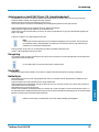
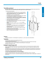
Drehfeldprüfung (> 200 V AC)
Schutzkleidung und isolierende Standorte können die Funktion beeinflussen.
Umfassen Sie vollflächig die Griffe L1 und L2 (siehe Bild auf Seite 7) unterhalb der mechanischen Markierung.
Legen Sie die Prüfspitzen L1 und L2 an zwei Außenleiter (Phasen) und prüfen Sie ob die Außenleiterspannung von z.B. 400 V an-
liegt.
Eine Rechtsdrehfolge (Phase an L1 vor Phase an L2) ist gegeben, wenn die "R" LED aufleuchtet.
Eine Linksdrehfolge (Phase an L2 vor Phase an L1) ist gegeben, wenn die "L" LED aufleuchtet.
Der Drehfeldbestimmung muss immer eine Prüfung mit vertauschten Prüfspitzen erfolgen. Dabei muss sich die Drehrichtung än-
dern.
Hinweis:
Die Drehfeldprüfung ist ab 200 V, 50/60 Hz (Phase gegen Phase) im geerdeten Drehstromnetz möglich. Die „dritte“ Phase (L3) wird
mit Hilfe eines Sensors im Gerät durch das Umfassen der Handteile simuliert.
Einhandprüfung (z.B. Schuko-Steckdose)
Durch den an der Prüfleitung am unteren Bereich der L1-Handhabe befindlichen Abstandhalter ist eine Arretierung der beiden
Handhaben möglich. Durch einfaches Drehen ist der Abstand der Prüfspitzen einstellbar. (Schuko / CEE).
Prüfstellenbeleuchtung
Durch kurzes Betätigen der L.H-Taste wird die Prüfstellenbeleuchtung ein- bzw. ausgeschaltet.
Setzen Sie diese sorgsam ein, da durch die zusätzliche Belastung die Batterien vorzeitig entleert werden.

Bedienung
Testboy® Profi III LED 9
ENGLISH
DEUTSCH
Durchgangsprüfung
(Zum Einschalten Prüfspitzen aneinander halten)
Legen Sie die Prüfspitzen an die zu prüfende Leitung, Sicherung o.ä. an. Bei einem Widerstand von 0 - 200 k leuchtet die grüne
"Rx/"-LED auf und ein akustisches Signal ertönt.
Lastzuschaltung / FI/RCD-Auslösetest, PE (Schutzleitertest)
Störspannungen und induktive sowie kapazitive Kopplung können bei der Spannungsprüfung durch gleichzeitiges Drücken der bei-
den FI/RCD Taster verringert werden. Dadurch wird eine geringere Impedanz eingeschaltet.
Der Spitzenstrom beim Betätigen der Taster liegt unterhalb von 0,3 A (Is).
Dieser zusätzliche Lastkreis ist überlastgeschützt und reduziert den Laststrom nach einigen Sekunden.
Diese eingebaute Last ermöglicht es, einen FI/RCD-Schutzschalter auszulösen.
Geprüft wird der FI/RCD (max. 30 mA @ 230 V AC) zwischen Phase und Schutzleiter.
Halten Sie dazu eine Prüfspitze an einen phasenführenden Leiter ( siehe Phasenprüfung ), die andere an den Schutzleiter und drü-
cken die beiden FI/RCD-Tasten so tief wie möglich.
Ohne Drücken der beiden Taster wird der FI im Normalfall nicht ausgelöst!
HINWEIS
Führen Sie den FI/RCD Test nur an fest installierten Anlagen und Stromkreisen durch. Ein Test an beweglichen
und nicht fest verdrahteten Geräten, Verlängerungsleitungen u.a. kann im Fehlerfall zu einem hohen Stromfluss
an den mit Schutzleiter verbundenen Metallteilen kommen!
Dieser Test ersetzt nicht die nach VDE 0100 Prüfungen an den FI/RCD Schutzschaltern!
Hierfür bietet Testboy® entsprechende Geräte an.
Reinigung
Sollte das Gerät durch den täglichen Gebrauch schmutzig geworden sein, kann das Gerät mit einem feuchten Tuch und etwas mil-
dem Haushaltsreiniger gereinigt werden. Niemals scharfe Reiniger oder Lösungsmittel zur Reinigung verwenden.
Zur Vermeidung elektrischer Schläge keine Feuchtigkeit in das Gehäuse eindringen lassen.
Wartung
Das Gerät benötigt bei Betrieb gemäß der Bedienungsanleitung keine besondere Wartung mit Ausnahme der Batterien.
Batteriewechsel
Sollte die Batterien sich entleert haben, ertönen kurz hintereinander Warnsignale und das Gerät schaltet sich aus. Wechseln Sie
bitte die Batterien umgehend um die Genauigkeit der Prüfwerte zu gewährleisten.
Vor dem Öffnen des Batteriefaches die Prüfspitzen vom Prüfkreis trennen!
Zum Wechsel der Batterien ist das Batteriefach am Hauptgehäuse zu öffnen. Lösen Sie dazu abwechselnd die Schrauben mittels
eines geeigneten Schraubendrehers. Achten Sie beim Einsatz der neuen Batterien auf die richtige Polarität.
Verschließen und verschrauben Sie das Batteriefach wieder sorgfältig zu.
Das Gerät zeigt ohne Batterien eine anliegende Spannung über dem ELV-Wert mit Hilfe einer LED an.
Bei niedrigeren Temperaturen unter 5 °C kann die Bereitschaft des Spannungsprüfers beeinträchtigt werden. Bitte sorgen Sie für
genügend Stromversorgung, indem Sie geeignete Batterien verwenden, die auch für den eingesetzten Temperaturbereich spezifi-
ziert sind!
Batterien gehören nicht in den Hausmüll. Auch in Ihrer Nähe befindet sich eine Sammelstelle!

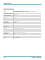
Technische Daten
10 Testboy® Profi III LED
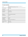
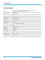
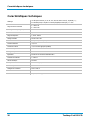
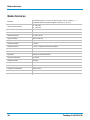
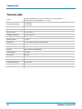
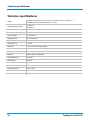
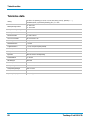
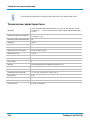
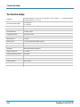
Technische Daten
Anzeige
16 LEDs für Spannung (12, 24, 48, 120, 230, 400, 690 und 1000 V), Polarität ( + ~ - ),
Durchgang (Rx/) und Phase/Drehfeld (R / L), FI + ELV
Nennspannungsbereich
6...1000 V AC
6…1400 V DC
Drehfeldanzeige
Ja
Indikation
0,85 Un
Frequenzbereich
0, 16.66...500 Hz
Schaltbare Last
30 mA bei 230 V AC
Einschaltdauer
30 s an \ 240 s aus
Nominaler Strom In
< 3,5 mA
Spitzenstrom Is
< 0,3 A, bei gedrückten Tastern (FI/RCD)
Phasenprüfung Pol
> 100 V AC
Schutzklasse
II
Impedanz
625 k bei ELV-Wechselspannung
Durchgangsprüfung
0...200 k
Klimakategorie
N normal
Betriebstemperatur
-15 bis +45 °C, bei > 95% RH bis +31 °C
Schutzart
IP 65
Überspannungskategorie
CAT IV 1000 V
Prüfnorm
EN 61243-3:2014
Spannungsversorgung
2x 1,5 V Typ AAA Micro

Table of contents
Testboy® Profi III LED 11
ENGLISH
ENGLISH
Table of contents
Safety information 12
Intended use 13
Disclaimer 13
Disposal 14
Operation 14
Safety information 15
General 15
Function 15
Self-Test / Auto Power-Off 15
Checking the DC voltage 16
Checking the AC voltage 16
Phase test 16
Phase sequence testing (> 200 V AC) 16
One-hand test (e.g. Schuko socket) 16
Test location lighting 16
Continuity test 16
Load connection / FI/RCD trigger test, PE (protective earth test) 17
Cleaning 17
Maintenance 17
Replacing the battery 17
Technical data 18

Safety information
12 Testboy® Profi III LED
Safety information
WARNING
Before using, carefully read these instructions. If the instrument is not used as intended by the manufacturer, the
protection already provided can be influenced.
WARNING
Sources of danger are, for example, mechanical parts, which may cause serious personal injury. Objects are also at
risk (e.g. damage to the instrument).
WARNING
An electric shock can result in death or serious personal injury and endanger the function of objects (e.g. damage to
the instrument).
WARNING
Unauthorised modification and / or changes to the instrument are not permitted, for reasons of safety and approval
(CE). In order to ensure safe and reliable operation using the instrument, you must always comply with the safety
instructions, warnings and the information contained in the section "Intended use".
WARNING
Comply with the following specifications before using the instrument:
| Do not operate the instrument anywhere near electric welding equipment, induction heaters or other electromag-
netic fields.
| After abrupt changes in temperature, in order to stabilise the IR sensor, the instrument must be allowed to adjust
to the new ambient temperature for approx. 30 minutes before using it.
| At lower temperatures of less than 5 °C, the readiness of the voltage tester can be impaired. Please provide suf-
ficient power supply by using suitable batteries which are also specified for the appointed temperature range!
| Do not expose the instrument to high temperatures for a long period of time.
| Avoid dusty and humid environments.
| The voltage tester and accessories are not toys, and must be kept out of the reach of children!
| When working in industrial facilities, comply at all times with the specifications of the accident prevention regula-
tions for electrical systems and equipment as established by the employer's liability insurance association.
Comply with the five safety rules:
1 Disconnect
2 Ensure that the instrument cannot be switched back on again
3 Ensure isolation from the power supply (check that there is no voltage on both poles)
4 Earth and short-circuit
5 Cover adjacent live parts
WARNING
| In comparison to the reference value of 100 k, a voltage tester with relatively low impedance does not indicate
all interference voltages with an original value above the ELV. On contact with the parts of the system to be test-
ed, due to discharge, the voltage tester can temporarily diminish the interference voltages up to a level less than
the ELV; however, after removing the voltage tester, the interference voltage returns to its original value.
| In comparison to the reference value of 100 k, a voltage tester with relatively high internal impedance at the
existing interference voltage cannot clearly indicate "operating voltage not present".
| If the indication "Voltage present" does not appear, before starting work, it is strongly recommended to insert the
earthing device.
| If the indication "Voltage present" appears for a part that is considered to be separate from the system, it is strongly
recommended to take additional action (e.g.: Use a suitable voltage tester, visual check of the separating point in the
electrical circuit etc.) to verify and determine the condition of the "Operating voltage not present" of the part of the
system to be tested and that the voltage indicated by the voltage tester is an interference voltage.

Safety information
Testboy® Profi III LED 13
ENGLISH
ENGLISH
Intended use
Only intended for use by qualified electricians and specialized personnel.
The instrument is only intended for the applications described in the operating instructions, such as AC, DC and continuity checks,
phase and rotating field tests. Any other usage is forbidden, and may result in accidents or destruction of the instrument. Any such
misapplication will result in the immediate expiry of all guarantee and warranty claims on the part of the operator against the manu-
facturer.
Everybody who uses this test instrument should be appropriately trained and be familiar with the required safety precautions and
the procedure for checking the correct function of the instrument, before and after using each time, particularly for hazards occur-
ring during voltage testing.
In order to protect the instrument from damage, remove the batteries if the instrument is not in use for a long pe-
riod of time.
We assume no liability for damage to property or personal injury resulting from improper handling or non-
compliance with the safety instructions. In such cases, any warranty claim becomes invalid. An exclamation mark
in a triangle indicates safety instructions in the operating instructions. Read the instructions through before be-
ginning initial commissioning. This instrument is CE-approved and thus fulfils the required guidelines.
We reserve the right to change specifications without prior notice © 2017 Testboy GmbH, Germany.
Disclaimer
The warranty claim expires in cases of damage caused by failure to comply with the instructions!
We assume no liability for any resulting damage!
Testboy is not responsible for damage resulting from
| failure to observe the instructions
| Changes to the product that have not been approved by Testboy
| The use of spare parts that have not been manufactured or approved by Testboy
| The use of alcohol, drugs or medication.
Accuracy of the operating instructions
These operating instructions have been compiled with due care and attention. No guarantee is given that the data, illustrations and
drawings are complete or correct. All rights reserved with regard to changes, printing mistakes and errors.

Operation
14 Testboy® Profi III LED
Disposal
Dear Testboy customer, purchasing our product gives you the option of returning the instrument to suitable collection points for
waste electrical equipment at the end of its lifespan.
The WEEE directive regulates the return and recycling of electrical appliances. Manufacturers of electrical appliances
are obliged to take back and recycle all electrical appliances free of charge. Electrical devices may then no longer be
disposed of through conventional waste disposal channels. Electrical appliances must be recycled and disposed of
separately. All equipment subject to this directive is marked with this logo.
Disposal of used batteries
As end user, you are legally obliged (battery law) to return all used batteries;
disposal by the household waste is forbidden!
Batteries containing contaminant material are labelled with this symbol indicating that they may not be disposed of in
normal domestic waste.
The designations for the essential heavy metals are, amongst others:
Cd = Cadmium, Hg = Mercury, Pb = Lead, Mn = Manganese, Li = Lithium.
You can return your used batteries to collection points in your community or anywhere where batteries are sold free-
of-charge.
Certificate of quality
All activities and processes carried out within Testboy GmbH relating to quality are subject to ongoing monitoring within the frame-
work of a Quality Management System. Furthermore, Testboy GmbH confirms that the testing equipment and instruments used dur-
ing the calibration process are subject to an ongoing inspection process.
Declaration of conformity
The product conforms to the most recent directives. For more information, go to www.testboy.de
Operation
Thank you very much for deciding on the Testboy® Profi III LED, a two-pole voltage tester with LED display. DC voltages (6 V to
1400 V) and AC voltages (6 V to 1000 V) against earth, polarity, rotating field and continuity tests of up to 200 k as well as
FI/RCD tests are carried out.
Due to the rotary distance piece, it is possible to operate with one hand for voltage measurement.
Because of the high protection class (IP65), the Testboy® Profi III LED can also be used under harsh conditions.

Operation
Testboy® Profi III LED 15
ENGLISH
ENGLISH
Safety information
You have decided on an appliance that offers you a high degree of safety. In order to ensure safe and correct application, before
using initially it is necessary to fully read these operating instructions.
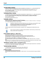
The following safety precautions are applicable:
| Immediately before using, carry out a function check of the voltage
tester (VDE regulation 0105, Part 1). Make sure that the test line and
appliance are fully serviceable. Check the appliance on a known
source of voltage, e.g. 230 V socket.
| Hereby, if the display fails to indicate one or more functions, do not use
the appliance and it must be checked by a specialist.
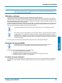
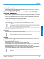
| Only hold the instrument on the handles (3) below the mechanical
mark (2), avoid contact with the test probes (1)! (Refer to the figure)
| Only carry out for isolation from the power supply on both poles!
| The appliance must not be operated in a moist environment!
| Do not use with the battery compartment open! Whilst replacing the
battery, the test probes must be removed from the test circuit.
| Correct indication is ensured in the temperature range of -15 °C to
+45 °C.
| Always keep the appliance dry and clean. Only use a moist cloth to
clean the housing.
| The additional warning symbol and vibration for voltages > 45 V AC /
110 V DC are only for warning of hazardous voltages, not for test pur-
poses!
| Immediately replace the batteries if a warning signal sounds shortly af-
ter switching on the instrument, or when the instrument is switched on
and immediately switches off.
| The different signals of the voltage tester (including the ELV limit value)
displayed must not be used for measurement.
General
Voltages have priority. If no voltage is applied at the test probes (< 6 V), the appliance is in the continuous test mode.
Function
To switch on the instrument, simply hold the test probes on one another.
In stand-by mode, the orange "Rx/" LED illuminates.
Attaching and removing the adapter for the test probes makes it easier to carry out tests at the socket.
For safe keeping, a suitable bracket is located at the captive test probe protection.
The nominal In current is a maximum of 3.5 mA.
Self-Test / Auto Power-Off
When initially switching on, either when inserting a new battery or when the test probes are held on one another if the instrument is
off (the "Rx/"-" LED does not illuminate), the instrument illuminates all optical displays (LED’s). Shortly after, the instrument
changes to the continuity check.
Hereby, if the display fails to indicate one or more functions, do not use the appliance and it must be checked by a specialist.
To test, in order to ensure that the instrument is ready to use, place the test probes on one another. This should be carried out im-
mediately before and after use. The green "Rx/" LED must clearly illuminate.
If the LED does not, or only faintly illuminates, replace the batteries.
If the appliance does not function with new batteries, it must be protected from being used incorrectly.
After a period without using, the instrument automatically switches off by the "Auto Power Off" function.
Thereby, the orange "Rx/" LED goes out. To switch on the instrument again/self test, momentarily hold the test probes on one
another.

Operation
16 Testboy® Profi III LED
Checking the DC voltage
When placing the probes on an AC voltage within the rated voltage range, one of the lower (12 V +~-) LED's and the LED arranged
above it illuminate according to the voltage applied. The lower LED's indicate the polarity at the test probes L2! ( + or - )
If the threshold value of approx. 110 V is exceeded, the ELV LED also illuminates and lucid vibration can be felt. This indicates
a hazardous voltage is present!
The ELV LED must not be used for measurement.
Checking the AC voltage
When placing the probes on an AC voltage within the rated voltage range, both of the lower (12 V +~-) LED's and the LED's ar-
ranged above them illuminate according to the voltage applied. The simultaneous illumination of the lower LED's indicates AC volt-
age (~).
If the threshold value of approx. 45 V is exceeded, the ELV LED also illuminates and lucid vibration can be felt. This indicates a
general hazardous voltage!
The ELV LED must not be used for measurement.
Phase test
Protective clothing and insulation locations can influence the function!
With the test probe "L2", contact the large hand parts of a conductor. If a phase (Pol >100 V AC), min. 100 V~ is applied, the
"<L" LED illuminates! Momentarily illumination of the 12 V LEDs has no significance here.
For determining the phase conductor, the perceptibility of the indication can be impaired, e.g. by insulating fix-
tures to protect against direct contact, in adverse positions, for example on wooden ladders or insulating floor
coverings, of a voltage not earthed or also in adverse lighting conditions.
For safety, check for two-pole deenergization.
The phase can also be determined by checking the external conductor against the protective earth. The voltage applied should be
indicated at the phase conductor.
During this test, make sure that an additional current flows across the protective conductor. This is added to that
already existing and could trigger the circuit breaker (FI))!
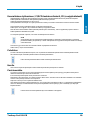
Phase sequence testing (> 200 V AC)
Protective clothing and insulation locations can influence the function.
Fully encompass the handles L1 and L2 (refer to the figure on Page 15) below the mechanical mark.
Place the probes L1 and L2 on two external conductors (phases) and check to see whether the external conductor voltage of,
e.g. 400 V is applied.
A clockwise sequence (phase at L1 before phase at L2) is present if the "R" LED illuminates.
An anticlockwise sequence (phase at L2 before phase at L1) is present if the "L" LED illuminates.
Determination of the phase sequence must always be carried out with a check for transposed probes. Thereby, the phase se-
quence must change.
Please note:
The phase sequence test is possible in earthed AC voltage mains supply from 200 V, 50/60 Hz (phase to phase). The ”third“ phase
(L3) is simulated with the aid of a sensor in the instrument, by using the hand parts.
One-hand test (e.g. Schuko socket)
Locking both hand parts is possible by the distance piece located on the test line in the lower section on the L1 hand parts. The dis-
tance of the test probes can be adjusted by simply rotating. (Schuko / CEE).
Test location lighting
The lighting at the test location is switched on and off by momentarily activating the L.H button.
Carefully insert these because, due to the additional load, the batteries become discharged prematurely.
Continuity test
(To switch on, place the test probes on one another)
Place the test probes on the line to test, fuse or similar. For a resistance of 0 - 200 k, the green "Rx/" LED illuminates and an
acoustic signal sounds.

Operation
Testboy® Profi III LED 17
ENGLISH
ENGLISH
Load connection / FI/RCD trigger test, PE (protective earth test)
Interference voltages and inductives, as well as capacitive coupling can be reduced during the voltage test by simultaneously press-
ing both buttons, FI/RCD. Thereby, a lower impedance is switched on.
When activating the button, the peak current is less than 0.3 A (Is).
This additional load circuit is protected against overloading and reduces the load current after a few seconds.
This in-built load enables a FI/RCD circuit breaker to trigger.
The FI/RCD (max. 30 mA @ 230 V AC) is tested between the phase and protective earth.
Hold a test probe on a phase-carrying conductor ( refer to the phase test ), the other at the protective earth and press in both
FI/RCD buttons as far as possible.
In the normal case, the FI is not triggered without pressing both buttons!
NOTE
Only carry out the FI/RCD test on fixed installations and power circuits. In the event of a fault, a test on movable
and devices not permanently wired, extension leads, amongst other things, can result in excessive current flow
in metallic parts connected to the protective earth.
This test does not replace tests on the FI/RCD protective earth, in accordance with VDE 0100!
For this, Testboy® provides the appropriate instruments.
Cleaning
Use a damp cloth and mild household detergent to clean the instrument should it become soiled through daily use. Never use ag-
gressive cleaning agents or solvents to clean the instrument.
To prevent electric shocks, do not allow moisture to ingress the housing.
Maintenance
During operation in accordance with the operating instructions, the instrument does not require special maintenance, with the ex-
ception of the batteries.
Replacing the battery
If the batteries are discharged, warning signals are emitted successively and the instrument automatically switches off. Immediately
replace the batteries in order to ensure accuracy of the test values.
Before opening the battery compartment, disconnect the test probes from the test circuit!
To replace the batteries, open the battery compartment on the main housing. Use a suitable screwdriver and alternately release the
screws. When inserting the batteries, ensure that the polarity is correct.
Carefully close and lock the battery compartment with the screws.
With the aid of an LED and without batteries, the instrument indicates an applied voltage of more than the ELV value.
At lower temperatures of less than 5 °C, the readiness of the voltage tester can be impaired. Please provide sufficient power supply
by using suitable batteries which are also specified for the appointed temperature range!
Batteries must not be disposed of with normal domestic waste. There will be a collection point near you!

Technical data
18 Testboy® Profi III LED
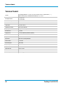
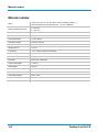
Technical data
Display
16 LEDs for voltage (12, 24, 48, 120, 230, 400, 690 and 1000 V), polarity ( + ~ - ),
continuity (Rx/) and phase/rotating field (R / L), FI + ELV
Rated voltage range
6...1000 V AC
6…1400 V DC
Phase sequence indication
Yes
Indication
0.85 Un
Frequency range
0, 16.66...500 Hz
Switchable load
30 mA at 230 V AC
Duty cycle
30 s on \ 240 s off
Nominal In current
< 3.5 mA
Peak current Is
< 0.3 A, with buttons pressed (FI/RCD)
Phase test Pol
> 100 V AC
Protection class
II
Impedance
625 k for ELV AC
Continuity test
0...200 k
Climate category
N Normal
Operating temperature
-15 to +45 °C, at > 95% RH to +31 °C
Protection class
IP 65
Overvoltage category
CAT IV 1000 V
Testing standard
EN 61243-3:2014
Voltage supply
2x 1.5 V Type AAA Micro

Table des matières
Testboy® Profi III LED 19
ENGLISH
FRANÇAIS
Table des matières
Consignes de sécurité 20
Utilisation conforme 21
Exclusion de responsabilité 21
Élimination 22
Utilisation 22
Consignes de sécurité 22
Généralités 23
Fonction 23
Test autonome / Arrêt automatique 23
Contrôle de tensions continues 24
Contrôle des tensions alternatives 24
Contrôle des phases 24
Indication de phase (> 200 V CA) 24
Contrôle à une main (p.ex. prise Schuko) 24
Éclairage du points de mesure 24
Contrôle de continuité 25
Mise en circuit / Test de déclenchement du différentiel / RCD, PE (test
du conducteur de protection) 25
Nettoyage 25
Entretien 25
Remplacement des piles 25
Caractéristiques techniques 26

Consignes de sécurité
20 Testboy® Profi III LED
Consignes de sécurité
AVERTISSEMENT
Veuillez lire attentivement ce mode d'emploi avant l'utilisation. Si l'appareil n'est pas utilisé conformément aux indi-
cations du fabricant, la protection assurée par l'appareil peut-être remise en cause.
AVERTISSEMENT
Les sources de danger sont, p.ex., les éléments mécaniques pouvant causer de graves blessures aux personnes.
Il existe également des dangers pour les biens matériels (p.ex. un endommagement de l'appareil).
AVERTISSEMENT
L'électrocution peut entraîner la mort ou des blessures graves et nuire au fonctionnement de biens matériels (p.ex.
en endommageant l'appareil).
AVERTISSEMENT
Pour des raisons de sécurité et d'homologation (CE), il est interdit de transformer et/ou modifier l'appareil sans auto-
risation. Afin de garantir un fonctionnement sûr de l'appareil, les consignes de sécurité et avertissements, ainsi que
le chapitre « Utilisation conforme » doivent impérativement être respectés.
AVERTISSEMENT
Avant toute utilisation de l'appareil, respecter les consignes suivantes :
| Éviter d'utiliser l'appareil à proximité de postes de soudure électriques, de chauffages à induction et d'autres
champs électromagnétiques.
| En cas de changement soudain de température, l'appareil doit être exposé environ 30 minutes à la nouvelle
température ambiante avant son utilisation.
| En cas de températures inférieures à 5 °C, le testeur de tension peut ne pas fonctionner correctement. Garantir
une alimentation en courant suffisante en utilisant des piles adéquates, également spécifiées aux températures
d'utilisation !
| Ne pas soumettre l'appareil à des températures élevées pendant des périodes prolongées.
| Éviter les conditions ambiantes poussiéreuses et humides.
| Le testeur de tension et ses accessoires ne sont pas des jouets et doivent être tenus hors de portée des enfants !
| Dans les établissements industriels, les règlements de prévention des accidents de l'Association des syndicats
professionnels en charge des installations et équipements électriques doivent être respectés.
Respecter les cinq règles de sécurité suivantes :
1 Déconnecter l'appareil
2 Empêcher son redémarrage
3 Le mettre hors tension (la mise hors tension doit être constatée sur les 2 pôles)
4 Mettre à la terre et court-circuiter
5 Couvrir les éléments sous tension voisins
AVERTISSEMENT
| Un testeur de tension présentant une impédance relativement faible n'affichera pas toutes les tensions parasites
d'une valeur initiale supérieure à la ELV par rapport à la valeur de référence de 100 k. En cas de contact avec
les pièces à contrôler de l'installation, le testeur de tension peut réduire les tensions parasites par décharge
temporaire jusqu'à un niveau inférieur à la ELV ; après le retrait du testeur de tension, la tension parasite atteint
cependant à nouveau sa valeur initiale.
| Un testeur de tension présentant une impédance interne relativement élevée n'affichera pas clairement « Ten-
sion de service indisponible » en cas de tension parasite par rapport à la valeur de référence de 100 k.
| Si l'affichage « Tension disponible » n'apparaît pas, il est vivement recommandé de mettre un dispositif de mise
à la terre en place avant la reprise du travail.
| Si l'affichage « Tension disponible » apparaît pour une pièce considérée comme séparée de l'installation, il est
vivement recommandé d'attester l'état « Tension de service indisponible » de la pièce de l'installation à contrôler
Sidan laddas ...
Sidan laddas ...
Sidan laddas ...
Sidan laddas ...
Sidan laddas ...
Sidan laddas ...
Sidan laddas ...
Sidan laddas ...
Sidan laddas ...
Sidan laddas ...
Sidan laddas ...
Sidan laddas ...
Sidan laddas ...
Sidan laddas ...
Sidan laddas ...
Sidan laddas ...
Sidan laddas ...
Sidan laddas ...
Sidan laddas ...
Sidan laddas ...
Sidan laddas ...
Sidan laddas ...
Sidan laddas ...
Sidan laddas ...
Sidan laddas ...
Sidan laddas ...
Sidan laddas ...
Sidan laddas ...
Sidan laddas ...
Sidan laddas ...
Sidan laddas ...
Sidan laddas ...
Sidan laddas ...
Sidan laddas ...
Sidan laddas ...
Sidan laddas ...
Sidan laddas ...
Sidan laddas ...
Sidan laddas ...
Sidan laddas ...
Sidan laddas ...
Sidan laddas ...
Sidan laddas ...
Sidan laddas ...
Sidan laddas ...
Sidan laddas ...
Sidan laddas ...
Sidan laddas ...
Sidan laddas ...
Sidan laddas ...
Sidan laddas ...
Sidan laddas ...
Sidan laddas ...
Sidan laddas ...
Sidan laddas ...
Sidan laddas ...
Sidan laddas ...
Sidan laddas ...
Sidan laddas ...
Sidan laddas ...
Sidan laddas ...
Sidan laddas ...
Sidan laddas ...
Sidan laddas ...
Sidan laddas ...
Sidan laddas ...
Sidan laddas ...
Sidan laddas ...
Sidan laddas ...
Sidan laddas ...
Sidan laddas ...
Sidan laddas ...
Sidan laddas ...
Sidan laddas ...
Sidan laddas ...
Sidan laddas ...
Sidan laddas ...
Sidan laddas ...
Sidan laddas ...
Sidan laddas ...
Sidan laddas ...
Sidan laddas ...
Sidan laddas ...
Sidan laddas ...
Sidan laddas ...
Sidan laddas ...
Sidan laddas ...
Sidan laddas ...
Sidan laddas ...
Sidan laddas ...
Sidan laddas ...
Sidan laddas ...
Sidan laddas ...
Sidan laddas ...
Sidan laddas ...
Sidan laddas ...
Sidan laddas ...
Sidan laddas ...
Sidan laddas ...
Sidan laddas ...
Sidan laddas ...
Sidan laddas ...
Sidan laddas ...
Sidan laddas ...
Sidan laddas ...
Sidan laddas ...
Sidan laddas ...
Sidan laddas ...
Sidan laddas ...
Sidan laddas ...
Sidan laddas ...
Sidan laddas ...
Sidan laddas ...
Sidan laddas ...
Sidan laddas ...
Sidan laddas ...
Sidan laddas ...
Sidan laddas ...
Sidan laddas ...
Sidan laddas ...
Sidan laddas ...
Sidan laddas ...
Sidan laddas ...
Sidan laddas ...
Sidan laddas ...
Sidan laddas ...
Sidan laddas ...
Sidan laddas ...
Sidan laddas ...
Sidan laddas ...
Sidan laddas ...
Sidan laddas ...
Sidan laddas ...
Sidan laddas ...
Sidan laddas ...
Sidan laddas ...
-
 1
1
-
 2
2
-
 3
3
-
 4
4
-
 5
5
-
 6
6
-
 7
7
-
 8
8
-
 9
9
-
 10
10
-
 11
11
-
 12
12
-
 13
13
-
 14
14
-
 15
15
-
 16
16
-
 17
17
-
 18
18
-
 19
19
-
 20
20
-
 21
21
-
 22
22
-
 23
23
-
 24
24
-
 25
25
-
 26
26
-
 27
27
-
 28
28
-
 29
29
-
 30
30
-
 31
31
-
 32
32
-
 33
33
-
 34
34
-
 35
35
-
 36
36
-
 37
37
-
 38
38
-
 39
39
-
 40
40
-
 41
41
-
 42
42
-
 43
43
-
 44
44
-
 45
45
-
 46
46
-
 47
47
-
 48
48
-
 49
49
-
 50
50
-
 51
51
-
 52
52
-
 53
53
-
 54
54
-
 55
55
-
 56
56
-
 57
57
-
 58
58
-
 59
59
-
 60
60
-
 61
61
-
 62
62
-
 63
63
-
 64
64
-
 65
65
-
 66
66
-
 67
67
-
 68
68
-
 69
69
-
 70
70
-
 71
71
-
 72
72
-
 73
73
-
 74
74
-
 75
75
-
 76
76
-
 77
77
-
 78
78
-
 79
79
-
 80
80
-
 81
81
-
 82
82
-
 83
83
-
 84
84
-
 85
85
-
 86
86
-
 87
87
-
 88
88
-
 89
89
-
 90
90
-
 91
91
-
 92
92
-
 93
93
-
 94
94
-
 95
95
-
 96
96
-
 97
97
-
 98
98
-
 99
99
-
 100
100
-
 101
101
-
 102
102
-
 103
103
-
 104
104
-
 105
105
-
 106
106
-
 107
107
-
 108
108
-
 109
109
-
 110
110
-
 111
111
-
 112
112
-
 113
113
-
 114
114
-
 115
115
-
 116
116
-
 117
117
-
 118
118
-
 119
119
-
 120
120
-
 121
121
-
 122
122
-
 123
123
-
 124
124
-
 125
125
-
 126
126
-
 127
127
-
 128
128
-
 129
129
-
 130
130
-
 131
131
-
 132
132
-
 133
133
-
 134
134
-
 135
135
-
 136
136
-
 137
137
-
 138
138
-
 139
139
-
 140
140
-
 141
141
-
 142
142
-
 143
143
-
 144
144
-
 145
145
-
 146
146
-
 147
147
-
 148
148
-
 149
149
-
 150
150
-
 151
151
-
 152
152
-
 153
153
-
 154
154
-
 155
155
-
 156
156


på andra språk
- italiano: TESTBOY Profi III LED Manuale utente
- slovenčina: TESTBOY Profi III LED Používateľská príručka
- Deutsch: TESTBOY Profi III LED Benutzerhandbuch
- português: TESTBOY Profi III LED Manual do usuário
- français: TESTBOY Profi III LED Manuel utilisateur
- dansk: TESTBOY Profi III LED Brugermanual
- română: TESTBOY Profi III LED Manual de utilizare
Relaterade papper
Andra dokument
-
Fluke FT140 Användarmanual
-
 METREL MD 1155 Användarmanual
-
Benning Duspol Analog Bruksanvisningar
-
Laserliner AC-tiveMaster Bruksanvisning
-
Amprobe AC50A Leakage Clamp Meter Användarmanual
-
 Meterman AC50 Bruksanvisningar
-
Megger MIT200 Användarmanual
-
Amprobe DM9C Användarmanual
-
-

