
R412008313/07.2014, Replaces: 12.2005, DE/EN/FR/IT/ES/SV
Pin-Belegung für D-SUB-Anschluss
Pin Assignment for D-SUB Connection
Affectation de broches pour connecteur D-SUB
Occupazione pin per attacco D-SUB
Ocupación de pines para la conexión D-SUB
Stiftsbeläggning för D-SUB-anslutning
VS LS04
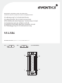
Belegungsplan | Assignment scheme | Plan d'affectation |
Schema di occupazione | Esquema de ocupación | Beläggningsschema
1
14
13
25
4 x
16 x
(7472D03429)

Deutsch
Maximalkonfiguration Ventilplatten:
4 x beidseitig betätigt, 16 x einseitig betätigt
Zu diesem Belegungsplan
Dieser Belegungsplan enthält wichtige Informationen für die sichere und
sachgerechte Herstellung der korrekten Pin-Belegung der D-SUB-Ansteuerung des
Ventilsystems LS04 mit 4 beidseitig und 16 einseitig betätigten Ventilplatten.
W Lesen Sie daher diesen Belegungsplan, bevor Sie den Gegenstecker des D-SUB-
Anschlusses konfigurieren.
W Bewahren Sie diesen Plan so auf, dass er für alle Benutzer zugänglich ist.
Mitgeltende Dokumente
W Bedienungsanleitung des VS LS04
W Technische Daten und Angaben gemäß Online-Katalog
(www.aventics.com/pneumatics-catalog)
Das müssen Sie beachten
W Benutzen Sie ein Anschlusskabel für 24 V über Trenntrafo mit Basisisolierung
nach EN 20178, Klassifikation VDE 0160.
W Verwenden Sie die Angaben dieses Plans nur zur Pin-Belegung eines
Gegensteckers für die D-SUB-Buchse des VS LS04 mit der genannten
Maximalkonfiguration.
W Beachten Sie die Angaben dieses Bedienungsplans sowie alle mitgeltenden
Dokumente und Begleitunterlagen.
W Halten Sie die nationalen Unfallverhütungsvorschriften am Einsatzort ein.
W Stellen Sie sicher, dass die Pin-Belegung des Gegensteckers nur von
qualifiziertem und geschultem Fachpersonal durchgeführt wird.
W Schalten Sie das System drucklos und spannungsfrei, bevor Sie mit Arbeiten am
VS beginnen.
Beschreibung und Einsatzbereich
Das VS LS04 verfügt über einen 25-poligen D-SUB-Anschluss an der EP-Endplatte
zur Ansteuerung der montierten Ventile.
Die Pin-Belegung dieses Anschlusses ist durch die gewählte Konfiguration
vorgegeben.
Um die korrekte Ventilansteuerung sicherzustellen, muss der Gegenstecker so
konfiguriert werden, dass jeder Pin des D-SUB-Anschlusses von der steuernden
Elektrik richtig angesteuert wird.
In Tab. ist die richtige Pin-Belegung des D-SUB-Anschlusses für das VS LS04 mit
der Anschlussvariante 8 dargestellt.
English
Maximum configuration for valve plates:
4x bistable, 16x mono-stable
About this assignment scheme
This assignment scheme contains important information on the safe and
appropriate establishment of the correct pin assignment for the D-SUB control of the
LS04 valve system with 4 bistable and 16 mono-stable valve plates.
W Read this assignment scheme thoroughly before configuring the mating plug of
the D-SUB connection.
W Keep this scheme in a location where it is accessible to all users.
Related documents
W VS LS04 operating instructions
W Technical data and information pursuant to the online catalog
(www.aventics.com/pneumatics-catalog)
The following must be observed
W Use a connection cable for 24 V via an isolating transformer with basic isolation
according to EN 20178, classification VDE 0160.
W Use the information in this scheme solely for the pin assignment of a mating plug
for the D-SUB bushing of the VS LS04 with the cited maximum configuration.
W Observe the information contained in this assignment scheme as well as all
related documents and accompanying documents.
W Adhere to national accident prevention regulations at the place of installation.
W Ensure that the pin assignment of the mating plug is only carried out by qualified
and trained specialists.
W Make sure the system is not under pressure or voltage before starting work on
the VS.
Vorkonfektionierte Kabel mit passendem D-SUB-Gegenstecker finden Sie im
Online-Katalog (www.aventics.com/pneumatics-catalog).
1
Description and applications
The VS LS04 has a 25-pin D-SUB connection on the EP end plate to control the
mounted valves.
The pin assignment of this connection is stipulated by the selected configuration.
To ensure correct valve control, the mating plug has to be configured in such a way
that each pin of the D-SUB connection is correctly controlled by the controlling
electronics.
The correct pin assignment of the D-SUB connection for the VS LS04 with connection
variant 8 is shown in Tab. .
Français
Configuration maximale embases de distributeurs:
4 x bistables, 16 x monostables
A propos du plan d’affectation
Ce plan comporte des informations importantes pour effectuer de manière sûre et
conforme l'affectation correcte des broches de la commande D-SUB du VS LS04
doté de 4 embases de distributeurs bistables et de 16 monostables.
W Lire donc attentivement ce plan d’affectation avant de configurer la fiche femelle
du connecteur D-SUB.
W Ranger le plan à un endroit tel que tous les utilisateurs puissent y accéder.
Autres documents applicables
W Mode d'emploi du VS LS04
W Données techniques et indications mentionnées dans le catalogue en ligne
(www.aventics.com/pneumatics-catalog)
Respecter les consignes suivantes
W Utiliser un câble de raccordement pour 24 V via un transformateur d'isolation
avec une isolation de base selon EN 20178, classification VDE 0160.
W Utiliser les indications de ce plan uniquement pour l'affectation des broches
d'une fiche femelle pour la douille D-SUB du VS LS04 avec la configuration
maximale indiquée.
W Respecter les indications de ce plan d'affectation ainsi que tous les autres
documents applicables et ceux fournis en annexe.
W Respecter les règlements de prévention des accidents sur le site d'utilisation.
W S'assurer que l'affectation des broches de la fiche femelle soit réalisée
uniquement par du personnel qualifié et formé.
W Mettre le système hors pression et hors tension avant toute opération sur le VS.
Description et domaine d'application
Le VS LS04 dispose d'un connecteur D-SUB à 25 pôles sur l'embase terminale EP
pour la commande des distributeurs montés.
L'affectation des broches de ce connecteur est déterminée par la configuration
sélectionnée.
Afin de garantir la commande correcte du distributeur, la fiche femelle doit être
configurée de telle sorte que chaque broche du connecteur D-SUB soit correctement
commandée par l'électrique de pilotage.
Le Tab. représente l'affectation correcte des broches du connecteur D-SUB pour
le VS LS04 avec la variante de raccordement 8.
Pre-assembled cables with suitable D-SUB mating plugs can be found in the
online catalog (www.aventics.com/pneumatics-catalog).
Des câbles pré-assemblés avec fiche femelle correspondante pour le
connecteur D-SUB sont présentés dans le catalogue en ligne
(www.aventics.com/pneumatics-catalog).
1
1
AVENTICS | VS LS04 | R412008313–BDL–001–AB | Deutsch/English/Français 1

Italiano
Configurazione massima delle piastre valvole:
4 x bistabili, 16 x monostabili
Informazioni sullo schema di occupazione
Questo schema di occupazione contiene informazioni importanti per una corretta
occupazione pin del pilotaggio D-SUB del sistema valvole LS04 con
4 piastre valvole bistabili e 16 monostabili nel rispetto delle norme e della sicurezza.
W Leggere quindi attentamente questo schema di occupazione prima di configurare
la controspina dell’attacco D-SUB.
W Conservare questo schema in modo che sia accessibile a tutti gli utenti.
Altri documenti validi
W Istruzioni per l’uso della VS LS04
W Dati tecnici e dati secondo il catalogo online
(www.aventics.com/pneumatics-catalog)
Cosa bisogna osservare
W Utilizzare un cavo di collegamento per 24 V tramite trasformatore di separazione
con isolamento base secondo EN 20178, classificazione VDE 0160.
W Utilizzare i dati di questo schema solo per l’occupazione pin di una controspina
per la boccola D-SUB della VS LS04 con la configurazione massima definita.
W Osservare i dati di questo schema di occupazione nonché tutti i documenti validi
e la documentazione di accompagnamento.
W Rispettare le norme di sicurezza nazionali vigenti in materia di infortuni sul luogo
d'impiego.
W Assicurarsi che l’occupazione pin della controspina sia eseguita solo da
personale tecnico qualificato e competente.
W Prima di eseguire un qualsiasi lavoro sulla batteria di valvole pneumatiche
togliere l'alimentazione elettrica e pneumatica del sistema.
Descrizione e campo d’impiego
La VS LS04 dispone di un attacco D-SUB a 25 poli sulla piastra terminale EP per il
pilotaggio delle valvole montate.
L’occupazione pin di questo attacco è prestabilita dalla configurazione scelta.
Per assicurare il pilotaggio corretto delle valvole, la controspina deve essere
configurata in modo tale che ogni pin dell’attacco D-SUB sia pilotato correttamente
dall’elettronica di comando.
Nella Tab. è riportata la corretta assegnazione pin dell’attacco D-SUB per la VS
LS04 con la variante di attacco 8.
Español
Configuración máxima de las placas de válvulas:
4 x biestables, 16 x monoestables
Acerca de este esquema de ocupación
Este esquema de ocupación contiene información importante para establecer de un
modo seguro y apropiado la correcta ocupación de pines del pilotaje D-SUB del
sistema de válvulas LS04 con 4 placas de válvulas biestables y 16 monoestables.
W Por ello, lea este esquema de ocupación antes de configurar el contraenchufe de
la conexión D-SUB.
W Guarde este esquema en un lugar al que puedan acceder fácilmente todos los
usuarios.
Documentos también vigentes
W Instrucciones de servicio del VS LS04
W Datos técnicos e indicaciones según el catálogo online
(www.aventics.com/pneumatics-catalog)
Cabe tener en cuenta
W Utilice un cable de conexión para 24 V a través de un transformador de
separación con aislamiento básico según EN 20178, clasificación VDE 0160.
W Utilice las indicaciones de este esquema únicamente para la ocupación de pines
de un contraenchufe para el casquillo D-SUB del VS LS04 con la configuración
máxima indicada.
W Tenga en cuenta las indicaciones de este esquema de ocupación, así como todos
los documentos también vigentes y documentos adicionales.
W Respete las normas nacionales de prevención de accidentes en el lugar de
aplicación.
W Asegúrese de que la ocupación de pines del contraenchufe sea efectuada sólo
por personal técnico cualificado y capacitado.
W Desconecte la presión y la tensión del sistema antes de comenzar a trabajar en
el VS.
Il cavo preconfezionato con controspina D-SUB adatta è riportato nel
catalogo online (www.aventics.com/pneumatics-catalog).
1
Descripción y zonas de utilización
El VS LS04 dispone de una conexión D-SUB de 25 polos en la placa final EP para el
pilotaje de las válvulas montadas.
La ocupación de pines de esta conexión viene dada por la configuración
seleccionada.
Para garantizar el pilotaje correcto de las válvulas, se debe configurar el
contraenchufe de tal manera que cada uno de los pines de la conexión D-SUB sea
pilotado correctamente por el sistema eléctrico de pilotaje.
En la Tab. se representa la correcta asignación de pines de la conexión D-SUB
para el VS LS04 con la variante de conexión 8.
Svenska
Maximal konfiguration ventilplattor:
4 x dubbelsidigt manövrerad, 16 x ensidigt manövrerad
Beträffande detta beläggningsschema
Detta beläggningsschema innehåller viktiga informationer för en säker och korrekt
stiftsbeläggning för D-SUB-aktiveringen av ventilsystemet LS04 med 4 dubbelsidigt
och 16 ensidigt manövrerade ventilplattor.
W Läs därför detta beläggningsschema innan D-SUB-anslutningens motkontakt
konfigureras.
W Förvara anvisningen så att den är lätt tillgänglig för alla som behöver använda de
Andra gällande dokument
W Bruksanvisning till VS LS04
W Tekniska data och uppgifter enligt online-katalogen
(www.aventics.com/pneumatics-catalog)
Detta skall observeras
W Använd en anslutningskabel för 24 V via separeringstransformatorn med
basisolering enligt EN 20178, klassificering VDE 0160.
W Använd endast uppgifterna i detta schema för stiftsbeläggning av en motkontakt
för D-SUB-dosan till VS LS04 med den angivna maximala konfigurationen.
W Observera uppgifterna i detta beläggningsschema och alla anda gällande
dokument och medföljande underlag.
W Iaktta de gällande nationella föreskrifterna för förebyggande av olycksfall.
W Kontrollera att motkontaktens stiftbeläggning endast utförs av kvalificerad och
utbildad fackpersonal.
W Stäng av systemet så det inte finns något, tryck, elektricitet eller spännning innan
arbeten på VS påbörjas.
Beskrivning och användningsområde
VS LS04 förfogar över en 25-polig D-SUB-anslutning på EP-ändplattan för aktivering
av de monterade ventilerna.
Stiftsbeläggningen av denna anslutning ger sig utifrån den valda konfigurationen.
För att säkerställa en korrekt ventilaktivering skall motkontakten konfigureras på
ett sådant sätt att varje stift på D-SUB-anslutningen aktiveras korrekt av den
styrande elektriken.
I Tab. visas korrekt stiftbeläggning av D-SUB-anslutningen för VS LS04 med
anslutningsvariant 8.
Encontrará un cable premontado con el correspondiente contraenchufe
D-SUB en el catálogo online (www.aventics.com/pneumatics-catalog).
Förkonfektionerade kablar med passande D-SUB-motkontakter finns
i online-katalogen (www.aventics.com/pneumatics-catalog).
1
1
AVENTICS | VS LS04 | R412008313–BDL–001–AB | Italiano/Español/Svenska 2

1
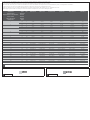
Pin-Belegung für D-SUB-Anschluss am VS LS04 mit 20 Ventilplätzen für Maximalkonfiguration:
Pin assignment for D-SUB connection on the VS LS04 with 20 valve positions for max. config.:
Affectation des broches pour connecteur D-SUB sur le VS LS04 doté de 20 emplacements de distributeurs pour la configuration maximale :
Occupazione pin per attacco D-SUB sulla VS LS04 con 20 posti valvola per configurazione max.:
Ocupación de pines para la conexión D-SUB en el VS LS04 con 20 lugares de válvula para la configuración máx.:
Stiftbeläggning för D-SUB-anslutning till VS LS04 med 20 ventilplatser för maximal konfiguration:
Ventilplatz Spule Pin Adernfarbe Wire color Couleur du fil Colore filo Color de hilo Ledarfärg
Valve position Solenoid
Emplacement de distributeur Bobine
Posto valvola Bobina
Lugar de válvula Bobina
Ventilplats Spole
1 14 1 weiß white blanc bianco blanco vit
12 2 braun brown brun marrone marrón brun
2 14 3 grün green vert verde verde grön
12 4 gelb yellow jaune giallo amarillo gul
3 14 5 grau gray gris grigio gris grå
12 6 rosa pink rose rosa rosa rosa
4 14 7 blau blue bleu blu azul blå
12 8 rot red rouge rosso rojo röd
5 14 9 schwarz black noir nero negro svart
6 14 10 violett violet violet viola violeta violett
7 14 11 grau/rosa gray/pink gris/rose grigio/rosa gris/rosa grå/rosa
8 14 12 blau/rot blue/red bleu/rouge blu/rosso azul/rojo blå/röd
9 14 13 weiß/grün white/green blanc/vert bianco/verde blanco/verde vit/grön
10 14 14 braun/grün brown/green brun/vert marrone/verde marrón/verde brun/grön
11 14 15 weiß/gelb white/yellow blanc/jaune bianco/giallo blanco/amarillo vit/gul
12 14 16 gelb/braun yellow/brown jaune/brun giallo/marrone amarillo/marrón gul/brun
13 14 17 weiß/grau white/gray blanc/gris bianco/grigio blanco/gris vit/grå
14 14 18 grau/braun gray/brown gris/brun grigio/marrone gris/marrón grå/brun
15 14 19 weiß/rosa white/pink blanc/rose bianco/rosa blanco/rosa vit/rosa
16 14 20 rosa/braun pink/brown rose/brun rosa/marrone rosa/marrón rosa/brun
17 14 21 weiß/blau white/blue blanc/bleu bianco/blu blanco/azul vit/blå
18 14 22 braun/blau brown/blue brun/bleu marrone/blu marrón/azul brun/blå
19 14 23 weiß/rot white/red blanc/rouge bianco/rosso blanco/rojo vit/röd
20 14 24 braun/rot brown/red brun/rouge marrone/rosso marrón/rojo brun/röd
0V GND 25 weiß/schwarz white/black blanc/noir bianco/nero blanco/negro vit/svart
2 4 x
3 16 x


AVENTICS GmbH
Ulmer Straße 4
30880 Laatzen
Phone +49 (0) 5 11-21 36-0
Fax: +49 (0) 511-21 36-2 69
www.aventics.com
Further addresses:
www.aventics.com/contact
The data specified above only serve to
describe the product. No statements
concerning a certain condition or suitability
for a certain application can be derived
from our information. The given
information does not release the user from
the obligation of own judgement and
verification. It must be remembered that
our products are subject to a natural
process of wear and aging.
An example configuration is depicted on
the title page. The delivered product may
thus vary from that in the illustration.
Translation of the original operating
instructions. The original operating
instructions were created in the German
language.
R412008313–BDL–001–AB/07.2014
Subject to modifications. © All rights
reserved by AVENTICS GmbH, even and
especially in cases of proprietary rights
applications. It may not be reproduced or
given to third parties without its consent.
-
 1
1
-
 2
2
-
 3
3
-
 4
4
-
 5
5
-
 6
6


AVENTICS Series LS04 Pin Assignment for D-SUB Connection 4x - 16x Assembly Instructions
- Typ
- Assembly Instructions
- Denna manual är också lämplig för
på andra språk
- italiano: AVENTICS Series LS04 Pin Assignment for D-SUB Connection 4x - 16x
- español: AVENTICS Series LS04 Pin Assignment for D-SUB Connection 4x - 16x
- Deutsch: AVENTICS Series LS04 Pin Assignment for D-SUB Connection 4x - 16x
- français: AVENTICS Series LS04 Pin Assignment for D-SUB Connection 4x - 16x
Relaterade papper
-
AVENTICS Series LS04 Pin Assignment for D-SUB Connection 12x Assembly Instructions
-
-
-
-
AVENTICS Series CON-MP Assembly Instructions
-