Murray 309008X51 Bruksanvisning
- Kategori
- Leksaker
- Typ
- Bruksanvisning
Denna manual är också lämplig för

OPERATOR’S MANUAL
en
fr
de
it
nl
el
Instruction Book - Riding mower
Manuel de l’utilisateur - Tondeuse autoportée
Betriebsanleitung - Aufsitzmäher
Istruzioni per l’uso - Trattore tagliaerba
Gebruikshandleiding - Zitmaaier
Eγχειρίδιο οδηγών χρήσης - Xορτοκοπτικού για εποχούμεν χειροτή
Driftsvejledning - Plænetraktor
Bruksanvisning - Rider
Användarhandbok - Trädgårdtraktor
Juhend - Traktorniiduki
Használati Útmutató - Önjáró fûnyíró gép
Руководcтво - Koилка c cиденьем
Manual Part No. 1741751
Revision 00
Rev. Date 01/2008
TP 199-4843-00-RD-R
CAUTION: Read and
follow all instructions.
Model No. 309007x51A
Product Type
Mfg. No. Description
7800336 30” Murray CE Riding Mower
da
no
sv
et

2
1741751
1
1
2
6
3
4 (17x47)
5 (1001054)
5
1
2
3
4
1
2
8
6 (17x146)
7 (25x3)
3
1
2
3
4
4
5
8
6 (2x82)
7 (14x79)
6 (2x82)
1
2
4
3
45
6
7
9
1
5
6
7
1
8
9

3
1741751
7
7
8
2
6
4
9
5
1
10
3
11
1
2
3
1
2
12

4
1741751
1
2
3
4
5
6
7
13
14
7
4
1
2
3
15
3
2
16
1
2
3
4
5
6
1
17
3
2
2
1
18
5
3
4

5
1741751
19
4
1
20
5
3
21
3
22
1
4
2
5
5

6
1741751
23
1
2
3
4
4
5
6
24
12
7
8
9
10
11
2
7
13
6

7
1741751
25
3
3
4
4
5
6
9
7
5
8
7
10
10
11
1

8
1741751
12 3
4
5
6
7
8
26
9
MAX 90N
+
MAX 150N
+
10 11
12
13
1
2
3
4
5
67
8
9
10 11 12
13
14
15
27
28
1001054
2x82
14x79
17x47
327349
17x146
25x3

en
9
1741751
CONTENTS
INTERNATIONAL PICTORIALS 9
OWNER’S INFORMATION 10
SAFE OPERATION PRACTICES 10
ASSEMBLY 11
OPERATION 12
MAINTENANCE CHART 14
MAINTENANCE 14
TROUBLE SHOOTING CHART 17
INTERNATIONAL PICTORIALS
IMPORTANT: The following pictorials are lo-
cated on your unit or on literature supplied
with the product. Before you operate the
unit, learn and understand the purpose for
each pictorial.
NOTE: Illustrations and pictorials begin
on page 2.
Safety Warning Pictorials (Figure 26)
1 WARNING
2 IMPORTANT: Read Owner’s Manual
Before Operating This Machine.
3 WARNING: Thrown Objects. Keep
Bystanders Away. Read User Instructions
Before Operating This Machine.
4 WARNING: Do Not Use This Machine On
Slopes Greater Than 10 Degrees.
5 DANGER: Keep People, Especially
Children, Away From Unit.
6 DANGER: No Step.
7 DANGER: Keep Feet And Hands Away
From Rotating Blade.
8 DANGER: Disconnect Spark Plug Wire
Before Servicing Unit.
9 WARNING: Hot Surface.
10 WARNING: Use Caution When Connecting
Or Disconnecting Accessories.
11 WARNING: Crushed Fingers.
12 IMPORTANT: Follow Instructions In
Owner’s Manual To Level The Deck.
13 WARNING: Stay Clear Of Mower Blade As
Long As Engine Is Running.
Control And Operating Pictorials
(Figure 27)
1 Engine Start
2 Lights
3 Engine Run
4 Engine Stop
5 Engine Run
6 Brake
7 Parking Brake
8 Clutch
9 Slow
10 Fast
11 Choke
12 Oil
13 Blade Rotation Control
14 Raise
15 Fuel

en
10
1741751
OWNER’S INFORMATION
Know your product: If you understand the unit
and how the unit operates, you will get the best
performance. As you read this manual, compare
the illustrations to the unit. Learn the location
and the function of the controls. To help prevent
an accident, follow the operating instructions
and the safety rules. Keep this manual for future
reference.
WARNING: Look for this symbol to indicate
important safety precautions. This symbol
indicates: “Attention! Become Alert! Your
Safety Is At Risk.”
Responsibility Of The Owner
WARNING: This cutting machine is
capable of amputating hands and
feet and throwing objects. Failure
to observe the following safety instructions
could result in serious injury or death to
the operator or bystanders.
The responsibility of the owner is to
follow the instructions below.
SAFE OPERATION PRACTICES
For Ride--On (Riding)
Rotary Mower Machines
Training
1. Read the instructions carefully. Be familiar
with the controls and the proper use of the
equipment.
2. Never allow children or people unfamiliar
with these instructions to use the mower.
Local regulations may restrict the age of
the operator.
3. Never mow while people, especially
children, or pets are nearby.
4. Keep in mind that the operator or user is
responsible for accidents or hazards occur-
ring to other people or their property.
5. Do not carry passengers.
6. All drivers should seek and obtain pro-
fessional and practical instruction. Such
instruction should emphasize:
a. the need for care and concentration
when working with ride--on machines;
b. control of a ride--on machine sliding
on a slope will not be regained by the
application of the brake. The main
reasons for loss of control are:
• insufficient wheel grip;
• being driven too fast;
• inadequate braking
• the type of machine is unsuitable
for its task;
• lack of awareness of the effect of
ground conditions, especially
slopes;
• incorrect hitching and load dis-
tribution.
Preparation
1. While mowing, always wear substantial
footwear and long trousers. Do not operate
the equipment when barefoot or wearing
open sandals.
2. Thoroughly inspect the area where the
equipment is to be used and remove all ob-
jects which may be thrown by the machine.
3. WARNING -- Petrol is highly flammable.
a. Store fuel in containers specifically de-
signed for this purpose.
b. Refuel outdoors only and do not
smoke while refuelling.
c. Add fuel before starting the engine.
Never remove the cap of the fuel tank
or add petrol while the engine is run-
ning or when the engine is hot.
d. If petrol is spilled, do not attempt to
start the engine but move the machine
away from the area of spillage and
avoid creating any source of ignition
until petrol vapours have dissipated.
e. Replace all fuel tanks and container
caps securely.
4. Replace faulty silencers.
5. Before using, always visually inspect to see
that the blades, blade bolts and cutter as-
sembly are not worn or damaged. Replace
worn or damaged blades and bolts in sets
to preserve balance.
6. On multi--blade machines, take care as ro-
tating one blade can c ause other blades to
rotate.
Operation
1. Do not operate the engine in a c onfined
space where dangerous carbon monoxide
fumes can collect.
2. Mow only in daylight or in good artificial
light.
3. Before attempting to start the engine, dis-
engage all blade attachment clutches and
shift into neutral.
4. Do not use on slopes of more than 10 de-
grees.
5. Remember there i s no s uch thing as a
“safe” slope. Travel on grass slopes re-
quires particular care. To guard against
overturning:
a. do not stop or start suddenly when
going up or downhill;
b. engage clutch slowly, always keep
machine i n gear, especially when tra-
velling downhill;
c. machine s peeds should be kept low
on slopes and during tight turns;
d. stay alert for humps and hollows and
other hidden hazards;
e. never mow across the face of the
slope, unless the mower is designed
for this purpose.
6. Use care when pulling l oads or using heavy
equipment.
a. Use only approved drawbar hitch
points.
b. Limit loads to those you can safely
control.
c. Do not turn sharply. Use care when
reversing.
d. Use counterweight(s) or wheel
weights when suggested in the In-
struction Book.
7. Watch out for traffic when crossing or near
roadways.
8. Stop the blades rotating before crossing
surfaces other than grass.
9. When using any attachments, never direct
discharge of material toward bystanders
nor allow anyone near the machine while in
operation.
10. Never operate the mower with defective
guards or shields, or without safety protec-
tive devices in place.
11. Do not change the engine governor set -
tings or overspeed the engine. Operating
an engine at excessive speed may in-
crease the hazard of personal injury.
12. Before leaving the operator’s position
a. disengage the power take--off and
lower the attachments;
b. change into neutral and set the park-
ing brake;
c. stop the engine and remove the key.
13. Disengage drive to attachments, stop the
engine, and disconnect the spark plug
wire(s) or remove the ignition key
a. before cleaning blockages or unclog-
ging chute;
b. before checking, cleaning or working
on the mower;
c. after striking a foreign object. Inspect
the mower for damage and make re -
pairs before restarting and operating
the equipment;
d. if the m achine starts to vibrate abnor -
mally (check immediately).
14. Disengage drive to attachments when
transporting or not in use.
15. Stop the engine and disengage drive to at -
tachment
a. before refuelling;
b. before removing the grass catcher;
c. before m aking height adjustment un -
less adjustment can be made from the
operator’s position.
16. Reduce the throttle setting during engine
run--out and, if the engine is provided with a
shut--off valve, turn the fuel off at the con-
clusion of mowing.
17. Before and when backing, look behind and
down for small children.
18. Use extra care when approaching blind
corners, shrubs, trees or other objects that
may obscure vision.
Maintenance and Storage
1. On multi--blade machines, take care as ro-
tating one blade can c ause other blades to
rotate.
2. When machine is to be parked, stored or
left unattended, lower the cutting means
unless a positive mechanical lock i s used.
3. Keep all nuts, bolts, and screws tight to be
sure the equipment is in safe working
condition.
4. Never store the equipment with petrol in the
tank inside a building where fumes may
reach an open flame or spark.
5. Allow the engine to cool before s toring in
any enclosure.
6. To reduce the fire hazard, keep the engine,
silencer, battery compartment and petrol
storage area free of grass, leaves, or ex-
cessive grease.
7. Check the grass catcher frequently for
wear or deterioration.
8. Replace worn or damaged parts for s afety.
9. If the fuel tank has to be drained, this
should be done outdoors.

en
11
1741751
ASSEMBLY
All fasteners are in the parts bag. Do not discard
any parts or material until the unit is assembled.
WARNING: Before doing any as-
sembly or maintenance to the
mower, remove the wire from the
spark plug.
NOTE: In this instruction book, left and right
describe the location of a part with the oper-
ator on the seat.
NOTE: Illustrations and pictorials begin on
page 2.
NOTE: To assemble the following loose
parts, use the fasteners shown at full s ize in
Figure 28.
How To Install The Seat (Figure 1)
1. Carefully remove the plastic bag from the
seat (1).
2. Raise the seat support (2) and secure in the
UP position with the seat support rod (6).
3. Align the holes in the seat (1) to the holes in
the seat support (2). Fasten the seat (1) to
the seat support (2) with the fasteners (4)
and (5).
4. Check the operating position of the seat (1).
If the seat (1) needs to be adjusted, loosen
the two wing bolts (5). Slide the seat (1) for-
ward or backward along the seat adjusting
holes (3). Tighten the wing bolts (5).
How To Assemble The Steering Wheel
(Figure 2)
1. Make sure the front wheels point forward.
2. Slide the tube (1) into the console (2).Make
sure the end of the tube (1) fits over the
steering bushing (3).
3. Attach the steering wheel (4) to the steer-
ing post (5) with screw (7) and washer (6).
4. Slide the steering wheel (4) and steering
post (5) into the tube (1) and console (2).
Push on the steering wheel (4).Thesteer-
ing post (5) will lock onto the pinion gear.
Pull on the steering wheel (4). Make sure
that the steering post (5) is locked in place.
5. Some models have an optional insert (8) in
the parts bag. Attach the insert (8) to the
centre of the steering wheel (4).
Maintenance Free Battery (Figure 3)
IMPORTANT: Before you attach the battery
cables to the battery, check the battery date.
The battery date tells if the battery must be
charged.
1. Raise the seat support and secure in the UP
position with the seat support rod.
2. Check the top of the battery (1) for the loca-
tion of the battery date.
3. If the battery (1) is put into service before
the battery date, the battery cables can be
attached without charging the battery (1).
See “How To Install The Battery Cables”.
4. If the battery (1) is put into service after the
battery date, the battery (1) must be
charged. See “How To Charge The Mainten-
ance Free Battery”.
How To Charge The Battery (Figure 3)
WARNING: When you charge the
battery, do not smoke. Keep the bat-
tery away from any sparks. The
fumes from the battery acid can cause an
explosion.
1. To disconnect the battery retainer (2) from
the battery tray (3), push in on the lower end
of the battery retainer (2).
2. Remove the battery (1) from the right side of
the unit.
3. Remove the protective cap from the battery
terminal.
4. Use a 12 volt battery charger to charge the
battery (1). Charge at a rate of 6 amperes
for one hour. If you do not have a battery
charger, have an authorized service centre
charge the battery.
5. Install the battery (1) and secure with the
battery retainer (2). Make sure the positive
(+) terminal (4) is on the right side.
How To Install The Battery Cables
(Figure 3)
WARNING: To prevent sparks, fasten
the red cable to the positive (+) ter-
minal before you connect the black
cable.
1. Remove the protective cap from the battery
terminal.
2. Fasten the red cable (5) and terminal
cover (9) to the positive (+) terminal (4)
with the fasteners (6) and (7).
3. Fasten the black cable 8 to the negative (--)
terminal with the fasteners (6) and (7).
Check The Tyres
Check the air pressure in the tyres. Tyres with
too m uch air pressure will cause the unit to ride
rough. Also, the wrong air pressure will keep the
mower housing from cutting level. The correct
air pressure is: Front Tyres 0,97 BAR (14 PSI),
Rear Tyres 0,69 BAR (10 PSI). The tyres were
over inflated for shipment.
Check The Level Of The Mower
Housing
Make sure the level of cut is still correct. After
you mow a short distance, look at the area that
was cut. If the mower housing does not cut level,
see the instructions on “How To Level The
Mower Housing” in the Maintenance section of
this instruction book.
How To Prepare The Engine
NOTE: The engine was shipped from the fac-
tory filled with oil. Check the level of the oil.
Add oil as needed.
See the engine manufacturer’s instructions for
the type of petrol and oil to use. Before y ou use
the unit, read the information on safety, oper-
ation, maintenance, and storage.
WARNING: Follow the engine manu-
facturer’s instructions for the type o
f
petrol and oil to use. Always use a
safety petrol container. Do not smoke when
adding petrol to the engine. When inside an
enclosure, do not fill with petrol. Before you
add petrol, stop the engine. Let the engine
cool for several minutes.
Important! Before You Start Mowing
U Check the engine oil.
U Fill the fuel tank with petrol.
U Check the level of the mower hous-
ing.
U Check the air pressure of the tyres.
U Attach the battery cables.
Final Assembly
1. Check all fasteners. Make sure all fasteners
are properly installed and are tight.
2. Check installation. Make sure all parts are
correctly installed.
WARNING: Make sure that the
grass bagger is properly as-
sembled and correctly installed.
The Grass Bagger must only be used when
fully assembled and correctly installed.

en
12
1741751
OPERATION
NOTE: Illustrations and pictorials begin on
page 2.
Location Of Controls (Figure 4)
Blade Rotation Control (1): Use the blade rota-
tion control to start and stop the rotation of the
blade.
Clutch / Brake Pedal (2): The pedal has two
functions. The first function is a clutch. The sec-
ond function is a brake.
Ignition Switch (3): Use the ignition switch to
start and stop the engine.
Shift Lever (4): Use the shift lever to change
the speed of the unit.
Lift Lever (5): Use the lift lever to change the
height of cut.
Parking Brake Lever (6): Use the parking brake
lever to engage the brake when you leave the
unit.
Throttle Control Lever (7): Use the throttle
control lever to increase or decrease the speed
of the engine.
Attachments
This unit can use many different attachments.
This unit can pull attachments like a lawn
sweeper, a lawn aerator, or a hopper spreader.
This unit can not use attachments that engage
the ground like a plough, a disk harrow, or a
cultivator.
For trailer and pull--behind attachments, the
maximum weight is 90 kg (200 lbs.).
How To Use The Throttle Control
(Figure 4 and Figure 5)
Use the throttle/choke control (7) to increase
or decrease the speed of the engine.
1. Move the throttle/choke control (7) com -
pletely forward to the CHOKE position to
start a cold engine.
1. The FAST position is marked with a detent.
For normal operation and when using a
grass bagger, move the throttle control to the
FAST position. For maximum charging of the
battery and for a cooler running engine, oper-
ate the engine in the FAST position.
2. The engine governor is set at the factory for
maximum performance. Do not adjust the
governor to increase the speed of the en-
gine.
How To Use The Blade Rotation Control
(Figure 4 and Figure 6)
Use the blade rotation control (1) to engage
the blade(s).
1. Before you start the engine, make sure the
blade rotation control (1) is in the DISEN-
GAGE position (8).
2. To rotate the blade, move the blade rotation
control (1) forward to lock the blade in the
ENGAGE position (9).
3. To stop the blade, move the blade rotation
control (1) to the DISENGAGE position (8).
Before you leave the operator’s position,
make sure the blade(s) has stopped rotating.
4. Before you ride the unit across a sidewalk or
a road, move the blade rotation control (1)
to the DISENGAGE position.
WARNING: Always keep your
hands and feet away from the
blade, deflector opening, and the
mower housing when the engine runs.
How To Use The Shift Lever
To change the forward speed or the direction of
the unit, follow the steps below.
CAUTION: Before you move the shift lever,
completely push the clutch/brake pedal (2)
forward to stop the unit. If the unit is not
stopped, the gearbox can be damaged.
1. (Figure 7) Completely push the clutch/
brake pedal (2) forward to s top the unit.
Keep your foot on the pedal.
2. (Figure 8) Move the throttle control lever
(7) to the SLOW position.
3. (Figure 9) To go forward, move the shift
lever (4) to a forward speed setting. To go
backward, move the shift lever (4) to re-
verse.
4. (Figure 7) Slowly release the clutch/brake
pedal (2). Do not keep your foot on the
pedal.
5. (Figure 8) Move the throttle control (7) to
the FAST position.
How To Use The Parking Brake
(Figure 7)
1. Completely push the clutch/brake pedal (2)
forward.
2. Lift the parking brake lever (6).
3. Remove your foot from the clutch/brake
pedal (2) and then release the parking
brake lever (6). Make sure the parking brake
will hold the unit.
4. To release the parking brake (6), completely
push the clutch/brake pedal (2) forward.
The parking brake will automatically release.
WARNING: Before you leave the
operator’s position, move the shift
lever to the neutral (N) position. Set
the parking brake. Move the blade rotation
control to the DISENGAGE position. Stop
the engine and remove the ignition key.
How To Change The Cutting Height
(Figure 10)
To change the cutting height, raise or lower the
lift lever (5) as follows.
1. Move the lift lever (5) forward to lower the
mower housing and back to raise the mower
housing.
2. When you ride on a sidewalk or road, move
the lift lever (5) to the highest position and
move the blade rotation control to the DIS-
ENGAGE position.
How To Stop The Unit (Figure 4)
1. Completely push the clutch/brake pedal (2)
forward to stop the unit. Keep your foot on
the pedal.
2. Move the blade rotation control (1) to the
DISENGAGE position.
3. Move the shift lever (4) to the NEUTRAL
position.
4. Set the parking brake (6).
WARNING: Make sure the parking
brake will hold the unit.
5. Move the throttle control (7) to the SLOW
position.
6. To stop the engine, turn the ignition key (3)
to the OFF position. Remove the key.
How To Transport The Unit
To transport the unit, follow the steps below.
1. Move the blade rotation control to the DIS-
ENGAGE position.
2. Raise the lift lever to the highest position.
3. Movethethrottlecontroltoapositionbe-
tween SLOW and FAST.
4. To go faster, move the shift lever to a faster
speed.
How To Install The Side Discharge
Attachment (Figure 11)
WARNING: To prevent the en-
gine from starting, disconnect
thewirefromthesparkplug.
Make sure the
attachment clutchblade
rotation control
is in the DISENGAGE
position.
The mulcher cover (1) lets you mulch the grass
for a clean, fine cut. To discharge the grass out
the side, install the side discharge attachment
(2) as follows.
1. Remove the two wingnuts (3) that secure
the mulcher cover (1).
2. Lift the mulcher cover (1). Mount the side
discharge attachment (2) onto the same
bolts that secured the mulcher cover (1).
3. Secure the side discharge attachment (2)
with the wingnuts (3).
4. To mulch, remove the side discharge at-
tachment (2) and mount the mulcher cover
(1) to the mower housing with the wingnuts
(3).
How To Operate With The Mower
Housing
WARNING: The mulch cover is a
safety device. Do not remove
the mulch cover. The deflector
forces the discharged material toward
the ground. Always keep the deflector
in the down position. If the deflector is
damaged, replace the deflector with
an original equipment part from an au-
thorized service center.
IMPORTANT: When you operate with the
mower housing, always operate with the
throttle control in the FAST position.
1. Start the engine.
2. Move the lift lever to a height of cut position.
In high or thick grass, cut the grass in the
highest position first and then lower the
mower housing to a lower position.
3. Move the throttle control to the SLOW posi-
tion.
4. Slowly move the blade rotation control to the
ENGAGE position.
5. Push the c lutch/brake pedal completely for-
ward.
6. Move the s hift lever to one of the speed set-
tings.

en
13
1741751
NOTE: When you mow in heavy grass or
mow with a bagger, put the shift lever in
the slowest speed.
7. Slowly release the clutch/brake pedal.
8. Move the throttle c ontrol to the FAST posi-
tion. If you need to go faster or slower, stop
the unit and move the shift lever to another
speed setting.
9. Make sure the level of cut is still correct.
After y ou mow a short distance, look at the
area that was cut. If the mower housing does
not cut level, see the i nstructions on “How To
Level The Mower Housing” in the Mainten-
ance section.
WARNING: For better control of the
unit, select a safe speed.
How To Operate On Hills
WARNING: Do not ride up or down
slopes that are too steep to back
straight up. Never ride the unit
across a slope.
1. Before you ride up or down a hill, move the
shift lever to the slowest speed.
2. Do not stop or change speed settings on a
hill. If you must stop, quickly push the clutch/
brake pedal forward and set the parking
brake.
3. To start again, make sure the shift lever is in
the slowest speed. Move the throttle c ontrol
to the S LOW position. Slowly release the
pedal.
4. If you must stop or start on a hill, always
have enough space for the unit to roll when
you release the brake and engage the clutch.
5. Be very careful when you change directions
on a hill. When on a slope or in a turn on a
hill, move the throttle control to the SLOW
position to help prevent an accident.
Before Starting The Engine
Check the oil
NOTE: The engine was shipped from the fac-
tory filled with oil. Check the level of the oil.
Add oil as needed. See the engine manufac-
turer’s instructions for the type of petrol and
oil to use.
1. Make sure the unit is level.
NOTE: Do not check the level of the oil
while the engine runs.
2. Check the oil. Follow the procedure i n the
engine manufacturer’s instructions.
3. If necessary, add oil until the oil reaches the
FULL mark on the dipstick. The quantity of oil
needed from ADD to FULL is shown on the
dipstick. Do not add too much oil.
Add Petrol
WARNING: Always use a safety
petrol container. Do not smoke
when adding petrol to the fuel tank.
Do not add petrol when you are inside an
enclosure. Before you add petrol, stop the
engine and let the engine cool for several
minutes.
(Figure 12) Fill the fuel tank (1) to the FULL (2)
position with regular unleaded petrol. Do not use
premium unleaded petrol. Make sure the petrol
is fresh and clean. Leaded petrol will increase
deposits and shorten the life of the valves.
How To Start The Engine
WARNING: The electrical system
has an operator presence system
that includes a sensor switch for
the seat. These components tell the
electrical system if the operator is sitting
on the seat. This system will stop the
engine when the operator leaves the seat.
For your protection, always make sure this
system operates correctly.
NOTE: The engine will not start unless you
depress the clutch/brake pedal and move the
blade rotation control to the DISENGAGE
position.
1. Push the c lutch/brake brake pedal complete-
ly forward. Keep your foot on the pedal.
2. Move the shift lever to the neutral (N) posi-
tion.
3. Make sure the blade rotation control is in the
DISENGAGE position.
4. Move the throttle control completely forward
to the CHOKE or FAST position. Some mo-
dels have a separate choke knob. Pull the
choke knob to the full CHOKE position.
5. Turn the ignition key to the START position.
NOTE: If the engine does not start after
four or five tries, move the throttle control
to the FAST position. Again try to start the
engine. If the engine will not start, see the
TROUBLE SHOOTING CHART.
6. Slowly move the throttle control to the SLOW
position.
7. To start a hot engine, move the throttle con-
trol to a position between FAST and SLOW.
Mowing And Bagging Tips
1. For a lawn to look better, check the cutting
level of the mower housing. See “How To
Level The Mower Housing” in the Mainten-
ance section.
2. For the mower housing to cut level, make
sure the tyres have the correct amount of air
pressure.
3. Every time you use the unit, check the blade.
If the blade is bent or damaged, immediately
replace the blade. Also, make sure the nut
for the blade is tight.
4. Keep the blade(s) sharpened. Worn blades
will cause the ends of the grass to turn
brown.
5. Do not cut or bag grass that is wet. Wet
grass will not discharge correctly. Let the
grass dry before cutting.
6. Use the left side of the mower housing to trim
near an object.
7. Discharge the cut grass onto the mowed
area. The result is a more even discharge of
cut grass.
8. When you mow large areas, start by turning
to the right so that the cut grass will dis-
charge away from shrubs, fences, driveways,
etc. After one or two rounds, mow in the op-
posite direction making left turns until fin-
ished.
9. If the grass is very high, cut two times to de -
crease the load on the engine. First cut with
the mower housing in the highest position
and then lower the mower housing for the
second cut.
10.For better engine performance and an even
discharge of the c ut grass, always operate
the engine with the throttle in FAST position.
11. When you use a bagger, operate the engine
with the throttle in FAST position and the shift
lever in first or second gear.
12.For better cutting performance and a quality
cut, mow with the shift lever in one of the
slower speeds.
13.After each use, clean the bottom and top of
the mower housing for better performance.
Also, a clean mower housing will help pre-
vent a fire.
Mulching Tips
When you use a mulcher attachment, the grass
is cut into very small pieces. These small pieces
will quickly break down. Because the nutrients
are returned to the soil, the lawn will need less
fertilizer. To correctly mulch the grass, follow the
steps below.
1. Set the throttle in the FAST position. Operate
the mower at a s lower ground speed. If
ground speed is too fast, the grass will not
haveanevencut.
2. Keep a sharp edge on the blade. A blade that
is not sharp will cause the ends of the grass
to become brown.
3. Make sure the grass is dry. Wet grass is diffi-
cult to cut.
4. Set the height of the mower housing so that
only the top third of the grass is cut. If the
grass is too high, set the height of the mower
housing to the maximum height. Then, lower
the mower housing for the second cut. Also,
instead of using the full width of the mower
housing, mulch at half the width.
5. Clean the bottom of the mower housing.
Grass and other debris can keep the mower
from working correctly.
6. If the grass grows fast, mulch more often.
7. If an area needs improvement, mulch a s ec-
ond time.

en
14
1741751
MAINTENANCE CHART
FREQUENCY MAINTENANCE REQUIRED COMMENTS
Daily or before each use Maintenance engine. Refer to the Engine Owner’s Manual.
Examine blade(s).
Check for cracks, wear, and excessive damage.
Remove debris from unit and mowing area.
Examine all rotating and sliding parts.
Check tire inflation. Refer to the Maintenance section.
Verify that the mower housing is level. Refer to the Maintenance section.
Examine V--belts. Check for cracks, wear, and excessive damage.
Check brake operation. Refer to the Operation and Maintenance
sections.
After completion of first 5 hours Change oil. Refer to the Engine Owner’s Manual.
After 25 hours Maintenance engine. Refer to the Engine Owner’s Manual.
Remove, examine, sharpen, and balance
blade(s).
Refer to Maintenance section.
Check adjustments:
a. Blade Rotation Control
b. Brake
c. Clutch
d. Steering
Refer to Maintenance section.
Lubricate chassis and mower housing. Refer to Where to Lubricate instructions.
Check the muffler:
a. Torque
b. For wear or burn out
c. Condition of spark arrestor, (if applicable).
Refer to Maintenance section.
Before storage of 30 days or more Prepare engine for storage. Refer to the Engine Owner’s Manual.
Drain fuel system. Refer to warnings in the Owner’s Manual.
Add fuel stabilizer. Refer to the Engine Owner’s Manual.
Prepare battery for storage:
a. Remove from unit.
b. Fully charge.
c. Move to cool dry place.
MAINTENANCE
NOTE: Illustrations and pictorials begin on
page 2.
General Recommendations
1. The owner’s responsibility is to maintain this
product. This will extend the life of the prod-
uct and is also necessary to maintain war-
ranty coverage.
2. Check the spark plug, drive brake, lubricate
the unit, and clean the air filter once a year.
3. Check the fasteners. Make sure all fasteners
are tight.
4. Follow the Maintenance section to keep the
unit in good operating condition.
WARNING: Before you make an in-
spection, adjustment, or repair to
the unit, disconnect the wire to the
spark plug. Remove the wire from the
spark plug to prevent the engine from
starting by accident.
NOTE: Torque is measured in foot pounds
(metric Nm). This measurement describes
how tight a nut or bolt must be. The torque is
measured with a torque wrench.
Inspect Blade (Figure 13)
WARNING: Before you inspect or
remove the blade, disconnect the
wire to the spark plug. If the blade
hits an object, stop the engine. Check the
unit for damage. The blade has sharp
edges. When you hold the blade, use
gloves or cloth material to protect your
hands.
If you keep the blade (1) sharp and inspect the
blade for damage, the blade will cut better and
be more safe to operate. Frequently check the
blade for excessive wear, cracks, or other dam-
age. Frequently check the nut (3) that holds the
blade (1). Keep the nut (3) tight. If the blade hits
an object, stop the engine. Disconnect the wire
to the spark plug. See if the blade is bent or
damaged. Check the blade adapter (5) for dam-
age. Before you operate the unit, replace dam-
aged parts with original equipment parts. See
the authorized service c entre in your area. Every
three years, have an authorized service person
inspect the blade or repl ace the old blade with
an original equipment part.
How To Remove And Install The Blade
(Figure 13)
1. Remove the mower housing. See the instruc-
tions on “How To Remove The Mower Hous-
ing”.
2. Use a piece of wood to keep the blade from
rotating.
3. Remove the nut (3) that holds the blade (1).
4. Check the blade (1) and the blade adapter
(5) according to the instructions for “Inspect
Blade”. Replace a badly worn or damaged
blade with an original equipment blade. See
an authorized service c entre in your area.
5. Clean the top and bottom of the mower hous-
ing. Remove all the grass and debris.
6. Mount the blade (1) and blade adapter (5)
on the mandrel (6).
7. Mount the blade (1) so that the hi--lift edges
(7) are up. If the blade is upside down, the
blade will not cut correctly and can cause an
accident.
8. Fasten the blade (1) with the original
washers and nut (3). Make sure the outside
rim of the Belleville washer (2) is against
the blade (1).
WARNING: Always keep the nut (3)
tight that holds the blade (1). A
loose nut or blade can cause an
accident.
9. Tighten the nut (3) that holds the blade (1) to
a torque of 30 foot pounds (41,5 Nm).
10.Install the mower housing. See “How To Re-
move The M ower Housing”.
How To Check The Blade Rotation
Control
WARNING: To prevent an injury, the
blade rotation control must operate
correctly.
In normal usage, the blade rotation control will
not require an adjustment. However, if the cut-

en
15
1741751
ting performance decreases or the quality of cut
is poor, make the following changes.
1. When you mow, make sure the throttle con-
trol is in the FAST position.
2. (Figure 6) Move the blade rotation control (1)
to the DISENGAGE position (8).
3. Stop the engine. Disconnect the wire from
the spark plug.
4. Check the blade(s). Keep a sharp edge on
the blade(s). A blade that is not sharp will
cause the tips of the grass to become brown.
5. If the quality of c ut has not improved, replace
the mower drive belt. See “How To Replace
The Mower Drive Belt”. If the replacing the
belt does not correct the problem, take the
unit to an authorized service centre.
6. Move the blade rotation control (1) to the
DISENGAGE position (8). Stop the engine.
Disconnect the wire from the spark plug.
7. (Figure 14) Check the operation of the blade
brake. Rotate the pulley with your hand.
Make sure that the brake pad (7) is pressed
tightly against the pulley.
WARNING: If the brake pad (7) does
not press tightly against the pulley,
take the unit to an authorized ser-
vice centre.
8. (Figure 6) Move the blade rotation control
(1) to the ENGAGE position (9).
9. (Figure 14) Check the pads for the blade
brake (7). If the pads are excessively worn
or damaged, replace the brake pad assem -
blies. Correct replacement parts and assist-
ance are available from an authorized
service centre.
10.Attach the wire to the spark plug. Mow for a
short distance and again check the operation
of the blade rotation control.
11. When you move the blade rotation control to
the DISENGAGE position, all movement will
stop within five seconds. If there is move-
ment of the belt or the blades continue to ro-
tate, engage and disengage the blade
rotation control five times to remove any ex-
cess rubber from a new mower drive belt. If
you need assistance, take the unit to an
authorized service centre.
How To Adjust The Shift Lever
(Figure 15)
If the NEUTRAL position on the shift lever does
not match neutral on the gearbox, adjust the
shift l ever as follows.
1. Stop the engine.
2. Disconnect the adjuster nut (2) from the
shifter yoke (3).
3. Make sure the shift lever is in the NEUTRAL
position.
4. Push the unit forward. M ake s ure the gear-
box is in neutral.
5. To align the adjuster nut (2) with the hole in
the shifter yoke (3), turn the adjuster nut
(2).
6. Connect the adjuster nut (2) to the shifter
yoke (3).
7. Make sure the NEUTRAL position on the
shift lever matches neutral on the gearbox.
How To Check And Adjust The Clutch
(Figure 16)
If the motion drive belt is loose, the clutch will
slip when; going up a hill, pulling a heavy load,
or the unit will not move forward. Adjust the
clutch as follows.
WARNING: Before you make an in-
spection, adjustment, or repair to
the unit, disconnect the wire to the
spark plug. Remove the wire from the
spark plug to prevent the engine from
starting by accident.
1. Check the routing of the motion drive belt.
Make sure the belt is installed c orrectly and
is inside all the belt guides.
2. Remove the cotter pin (1), washer (2), and
brake spring (3) from the adjustable nut
(4).
3. Disconnect the adjustable nut (4) from the
brake lever assembly (5).
4. Align the hole in the brake lever (5) with the
rear of the s lot in the frame.
5. Push the clutch rod (6) toward the rear. Turn
the adjustable nut (4) until the nut will fit
through the hole in the brake lever (5).
6. Assemble the adjustable nut (4) to the
brake lever (5) and to the brake spring (3).
Fasten with the washer (2) and cotter pin
(1).
7. If the belt still slips after the clutch has been
adjusted, then the motion drive belt is worn
or damaged and must be replaced. See
“How To Replace The Motion Drive Belt”.
How To Check And Adjust The Drive
Brake (Figure 17)
Completely push the clutch/brake pedal forward.
Set the parking brake. Move the shift lever to the
neutral (N) position. Push the unit. If the rear
wheels rotate, adjust or replace the brake pads.
Adjust the drive brake (1) as follows.
1. The location of the drive brake (1) is on the
left side of the gearbox (3).
2. Make sure the parking brake i s set and the
shift lever is in neutral (N). Turn the hex nut
(2) in a clockwise direction until the rear
wheels do not turn when the unit is pushed
forward.
3. Release the parking brake and push the unit.
If the unit does not roll, turn the hex nut (2)
in a c ounter--clockwise direction until the unit
rolls.
4. Set the parking brake. Push the unit. If the
rear wheels do not turn, the drive brake (1)
is correctly adjusted. Release the parking
brake.
WARNING: If you cannot correctly
adjust the drive brake, replace the
brake pads. Correct replacement
parts and assistance are available from an
authorized service centre.
How To Remove The Battery (Figure 3)
To charge or clean the battery (1), remove the
battery (1) from the unit as follows.
WARNING: To prevent sparks, dis-
connect the black battery cable (8)
from the negative (--) terminal be-
fore you disconnect the red cable (5).
WARNING: The battery contains
sulphuric acid which is harmful to
the skin, eyes and clothing. If the
acid gets on the body or clothing, wash
with water.
1. Disconnect the black cable (8) from the
negative ( --) terminal.
2. Disconnect the red cable (5) from the posi-
tive (+) terminal (4).
3. To disconnect the battery retainer (2) from
the battery tray (3), push in on the lower end
of the battery retainer (2).
4. Remove the battery (1) from the right side of
the unit.
How To Charge The Battery (Figure 3)
WARNING: When you charge the
battery, do not smoke. Keep the
battery away from any sparks. The
fumes from the battery acid can cause an
explosion.
1. Before you charge the battery (1), remove
the battery (1).
2. To charge the battery (1),usea12voltbat-
tery charger. Charge at a rate of 6 amperes
for 1 hour.
3. Install the battery (1).
WARNING: To prevent sparks,
fasten the red cable to the positive
(+) terminal before you connect the
black cable.
4. Fasten the red cable (5) to the positive (+)
terminal (4) with the fasteners as shown.
5. Fasten the black cable (8) to the negative
(--) terminal with the fasteners as shown.
6. Connect the battery retainer (2) to the bat-
tery tray (3).
How To Level The Mower Housing
If the mower housing is l evel, the blade will cut
easier and the lawn will look better.
WARNING: Before you make an in-
spection, adjustment, or repair to
the unit, disconnect the wire to the
spark plug. Remove the spark plug wire to
prevent the engine from starting by acci-
dent
1. Make sure the unit i s on a hard flat surface.
2. Check the air pressure in the tyres. If the air
pressure is incorrect, the mower housing will
not cut level. M ake s ure the tyres are inflated
to: Front Tyres 0,97 BAR (14 PSI), Rear
Tyres 0,69 BAR (10 PSI).
3. Open the cover (5).
4. (Figure 18) Move the lift lever (1) to the
LEVEL ADJUSTMENT position (2).
5. (Figure 18 and 19) Loosen the front and rear
adjuster knobs (4). Make sure both sides of
the mower housing are setting on a flat sur-
face. Also, make sure the lift links and adjust-
er plates are l oose and can easily move up
or down.
6. Tighten the front and rear adjuster knobs
(4). M ake sure the adjuster knobs (4) are
tight. If necessary, use a wrench to tighten
the adjuster knobs (4). For plastic adjuster
knobs (4), tighten to a torque of 7 foot
pounds (9,5 N--m). For metal adjuster
knobs (4), tighten to a torque of 10 foot
pounds (13,5 N--m).

en
16
1741751
7. (Figure 20) Raise the lift lever (1) from the
LEVEL ADJUSTMENT position (2) to a
CUTTING HEIGHT position (3).
8. Close the cover (5).
9. Mow for a short distance. If the height of cut
is not level, repeat the above s teps.
CAUTION: Do not operate with the mower
housing in the LEVEL ADJUSTMENT posi-
tion (2). If you operate in the LEVEL ADJUST-
MENT position (2), the mower housing and
blade will be damaged.
Where To Lubricate (Figure 21)
Lubricate the areas shown
with engine oil.
Apply grease with a brush to
the areas shown.
Models with grease fittings:
Lubricate with grease gun.
NOTE: Apply grease to the steering gear as-
sembly.
CAUTION: If the unit is operated in dry areas
that have sand, use a dry graphite spray to
lubricate the unit.
Check The Tyres
Check the air pressure in the tyres. Tyres with
too m uch air pressure will cause the unit to ride
rough. Also, the wrong air pressure will keep the
mower housing from cutting level. The correct
air pressure is: Front Tyres 0,97 BAR (14 PSI),
Rear Tyres 0,69 BAR (10 PSI).
How To Replace The Motion Drive Belt
(Figure 22)
1. Remove the mower housing. See the instruc-
tions on “How To Remove The Mower Hous-
ing”.
2. Completely push the pedal forward and en-
gage the parking brake.
3. Remove the idler pulley (1).
4. Loosen the belt guides (5) next to the drive
pulley (4).
5. Remove the motion drive belt (3) from the
drive pulley (4).
6. Remove the motion drive belt (1) from the
stack pulley (2).
7. A correct replacement part or assistance is
available from an Authorized Service Centre
in your area.
8. To install the motion drive belt, reverse the
above steps.
9. Check the routing of the motion drive belt
(1). M ake s ure the motion drive belt is in-
stalled c orrectly on the idler pulley (2).Make
sure the motion drive belt (1) is inside all
the belt guides.
10.Before you use the unit, check the adjust-
ment of the c lutch. See the instructions “How
To Check And Adjust The Clutch”.
11. Install the mower housing. See the instruc-
tions “How To Install The Mower Housing”.
How To Replace The Mower Drive Belt
(Figure 14)
1. Remove the mower housing. See the instruc-
tions on “How To Remove The Mower Hous-
ing”.
2. Pull the belt retainer (1) away from the idler
pulley (2) and remove the mower drive belt
(3).
3. Pull the brake pad (7) away from the jack-
shaft pulley (4) and remove the mower
drive belt (3).
NOTE: Replace the mower drive belt (3)
with an original equipment belt from an
authorized service center.
4. A correct replacement part or assistance is
available from an Authorized Service Centre
in your area.
5. To install the motion drive belt, reverse the
above steps.
6. Install the mower housing. See the instruc-
tions on “How To Install The Mower Hous-
ing”.
7. Before you mow, check the blade rotation
control. See the instructions on “How To Ad-
just The B lade Rotation Control”.
How To Remove The Mower Housing
1. (Figure 6) Move the blade rotation control
(1) to the DISENGAGE position (8).
2. (Figure 18) Move the lift lever (1) to the
LEVEL ADJUSTMENT position (2).
NOTE: Make sure the lift lever (1) is
locked in the LEVEL ADJUSTMENT posi-
tion (2).
3. (Figure 25) Remove the hair pins and the
washers from the rear suspension arms
(3). See illustrations “C” and “D”.
4. Remove the hair pins and washers from the
suspension links (4). See illustrations “A”
and “B”.
5. Disconnect the extension spring (5) from
the blade control rod (6). See illustration
“E”.
6. Disconnect the front hanger (9) from the
frame support. See illustration “F”.
7. Remove the mower drive belt (7) from the
stack pulley (8). See illustration “G”.
8. Pull the mower housing away from the right
side of the unit.
9. To operate without the mower housing, move
the lift lever to the TOP position.
10.To install the mower housing, reverse the
above steps.
11. Make sure the mower drive belt (7) is inside
all the belt guides (10) and is also below the
spacer tube (11).
How To Install The Wheels
If the wheels m ust be removed for service, make
sure they are installed as follows:
Front Wheel (Figure 23)
1. Make sure the valve stem (2) is to the out-
side. Slide the front wheel (1) onto the
spindle (3).
2. Fasten the front wheel (1) with washers (4)
and cotter pin (5). Bend the ends of the
cotter pin (5) apart to keep the front wheel
(1) on the spindle (3).
3. If your model has hub caps (6), install the
hub caps (6). Make sure the washers (4)
hold the hub caps (6) in place.
Rear Wheel (Figure 24)
1. Install the washers (7) and spacer (8) onto
the axle (9).
2. Mount the square key (10) in the key slot
(11).
3. Make sure the valve stem (2) is to the out-
side. Align the slot in the rear wheel (12)
with the square key (10). Slide the rear
wheel (12) on the axle (9).
4. Fasten the rear wheel (12) with washer (7)
and e--ring (13).
5. If your model has hub caps (6), install the
hub caps (6). Make sure the washer (7)
holds the hub caps (6) in place.
How To Replace The Fuse
If the fuse i s blown, the engine will not start.
Remove the fuse and replace with a 15 amp.
automotive fuse.
Storage (over 30 days)
At the end of each y ear, prepare the unit for stor-
age as follows.
1. Drain the fuel from the carburettor and the
fuel tank. Change the engine oil. See the en-
gine manufacturer’s instructions.
2. Clean the entire unit.
3. Charge the battery.
How To Order Replacement Parts
The replacement parts are shown either on the
back pages of this Instruction Book or in a sep-
arate Parts List Book.
Use only manufacturer’s authorized or approved
replacement parts. Do not use attachments or
accessories not specifically recommended for
this unit. In order to obtain proper replacement
parts you must supply the model number of your
mower (see nameplate).
Replacement parts, except for the engine, trans-
mission, transaxle or differential, are available
from the store where the mower was purchased
or a service shop recommended by the s tore.
W arranty service is available only through Autho-
rized Service Dealers. Locate your nearest dealer
in our locator map at www.murray.com.
Replacement parts for the engine, transaxle, or
transmission, are available from the manufac-
turer’s authorized service centre found in the
commercial pages of the telephone directory.
Also, see the i ndividual engine or transmission
warranties to order replacement parts.
When ordering the following information is re-
quired:
(1) The Model Number
(2) S erial Number
(3) Part Number
(4) Quantity

en
17
1741751
TROUBLE SHOOTING CHART
PROBLEM: The engine will not start.
1. Follow the steps, “How To Start The Engine”
in this book.
2. Electric--Start Models: Clean the battery ter-
minals. Tighten the cables.
3. Check for a l oose wire. Tighten the limit
switches. (See the wiring diagram.)
4. Drain the fuel tank. Clean the fuel line. Re-
place the fuel filter.
5. Remove the spark plug(s). Move the throttle
to the SLOW position. Turn the ignition key to
the ON position. Try to start the engine sev-
eral times. Install the spark plug.
6. Replace the spark plug.
7. Adjust the carburettor.
PROBLEM: The engine will not turn
over.
1. Follow the steps, “How To Start The Engine”
in this book.
2. Electric--Start Models: Charge the battery.
3. Replace the fuse.
4. Check the wiring harness for damage or a
loose connection. Repair the damaged wire.
5. Electric--Start Models: replace the solenoid.
Recoil--Start Models: replace the module.
PROBLEM: The engine is difficult to
start.
1. Adjust the carburettor.
2. Replace the spark plug.
3. Replace the fuel filter.
PROBLEM: The engine does not run
smooth or has a loss of power.
1. Check the oil.
2. Clean the air filter.
3. Clean the air screen.
4. Replace the spark plug.
5. The engine is working too hard. Use a l ower
gear.
6. Adjust the carburettor.
7. Replace the fuel filter.
PROBLEM: The engine does not run
smooth at fast speed.
1. Replace the spark plug.
2. Adjust the throttle control.
3. Clean the air filter.
4. Replace the fuel filter.
PROBLEM: The engine stops when the
blades are engaged.
1. Check the wiring harness for damage or a
loose connection. Repair the damaged wire.
2. Grass bag must be installed (applies only to
model with rear discharge grass bag).
PROBLEM: On slopes, the engine
stops.
1. Mow up and down slopes. Never mow
across a slope.
PROBLEM: The engine will not idle.
1. Replace the spark plug.
2. Clean the air filter.
3. Adjust the carburettor.
4. Adjust the throttle control.
5. Drain the fuel tank. Clean the fuel line. Re-
place the fuel filter.
PROBLEM: A hot engine causes a de-
crease in power.
1. Clean the air screen.
2. Check the oil.
3. Adjust the carburettor.
4. Replace the fuel filter.
PROBLEM: Excessive vibration.
1. Replace the blade.
2. Check for loose engine bolts.
3. Decrease the air pressure in the tyres.
4. Adjust the carburettor.
5. Check for a damaged belt or damaged
pulley. Replace the damaged parts.
PROBLEM: The grass does not dis-
charge correctly.
1. Stop the engine. Clean the mower housing.
2. Raise the height of cut.
3. Replace or s harpen the blade(s).
4. Move the s hift lever to a slower speed.
5. Move the throttle c ontrol to the FAST posi-
tion.
6. Replace the spring for the blade idler.
7. Clean the extension tube and the connector
tube (applies only to model with rear dis-
charge grass bag).
PROBLEM: The mower housing does
not cut level.
1. Check the air pressure in the tyres.
2. Adjust the l evel of the mower housing.
3. Check the front axle. If the front axle does
not freely pivot, loosen the axle bolt(s).
PROBLEM: The mower b lades will not
rotate.
1. Check the mower drive belt. Make sure the
belt is installed correctly.
2. Replace the mower drive belt.
PROBLEM: The unit will not move when
the clutch is engaged.
1. Check the motion drive belt. Make sure the
belt is installed correctly.
2. Adjust the c lutch.
3. Replace the motion drive belt.
PROBLEM: The unit moves slower or
stops when the clutch is engaged.
1. Adjust the c lutch.
2. Replace the motion drive belt.
PROBLEM: When the clutch/brake
pedal is released, belt noise can be
heard.
1. Temporary belt noise does not change the
operation of the unit. If belt noise is continu-
ous, check the routing of the belt. Make sure
the belt i s i nside all belt guides.
2. If the noise is continuous, adjust the clutch.
PROBLEM: The rear wheels spin over
uneven terrain.
1. Check the front axle. If the front axle does
not freely pivot, loosen the axle bolt(s).
PROBLEM: The transaxle is difficult to
shift between gears with the engine run-
ning and the clutch depressed.
1. Check the clutch adjustment to make sure
the belt stops when the clutch pedal is de-
pressed with the transaxle in (N) neutral.
2. Check the belt guides around the transaxle
drive pulley. Make sure the belt guides do not
touch the pulley.

fr
18
1741751
TABLE DES MATIERES
PICTOGRAMMES INTERNATIONAUX 18
INFORMATIONS GENERALES 19
POUR UNE UTILISATION EN TOUTE SECURITE 19
MONTAGE 20
FONCTIONNEMENT 21
TABLEAU D’ENTRETIEN 23
ENTRETIEN 24
TABLE DE DEPANNAGES 27
PICTOGRAMMES INTERNATIONAUX
REMARQUE IMPORTANTE: les pictogram-
mes suivants sont situés sur votre appareil
ou dans la documentation ci-jointe. Avant de
vous servir de la tondeuse, apprenez à re-
connaître chaque pictogramme.
REMARQUE: les illustrations et
pictogrammes commencent en page 2.
Pictogrammes d’avertissement (Figure 2 6)
1 Avertissement
2 REMARQUE IMPORTANTE : lire le manuel
de l’utilisateur avant de mettre la tondeuse
en marche.
3 AVERTISSEMENT : projection d’objets. Gar-
dez vos distances. Lire le manuel de l’utilisa-
teur avant de mettre la tondeuse en marche.
4 AVERTISSEMENT : ne pas utiliser la ton-
deuse sur des pentes de plus de 10 degrés.
5 DANGER: rester à l’écart, surtout les en-
fants, de l’appareil.
6 DANGER: ne pas poser le pied.
7 DANGER: gardez vos pieds et mains à dis-
tance de l a lame rotative.
8 DANGER: débrancher le câble de la bougie
avant toute i nspection de l’appareil.
9 AVERTISSEMENT : surface brûlante.
10 AVERTISSEMENT : prêter attention lors du
branchement et débranchement des acces-
soires.
11 AVERTISSEMENT : prendre garde à ne
pas s’écraser l es doigts.
12 IMPORTANT : pour régler le niveau du car -
ter du bloc de coupe, suivre attentivement
les instructions indiquées dans le Guide de
l’utilisateur.
13 AVERTISSEMENT : ne pas s’approcher de
la lame tant que le moteur tourne.
Pictogrammes de commande et de
fonctionnement (Figure 27)
1 Démarrage du moteur
2 Phares
3 Moteur en marche
4 Arrêt du moteur
5 Moteur en marche
6 Frein
7 Frein de stationnement
8 Embrayage
9 Ralenti
10 Rapide
11 Starter
12 Huile
13 Commande de rotation de la lame
14 Soulever
15 Essence

fr
19
1741751
INFORMATIONS GENERALES
Maîtrisez le produit : si vous connaissez le
produit et c omprenez comment celui-ci fonction-
ne, vous en obtiendrez les meilleurs résultats.
Au fur et à mesure que vous lisez le manuel,
consultez les illustrations ci-jointes. Sachez re-
connaître l’emplacement et la fonction de cha -
que commande. Afin de prévenir tout accident,
suivez les instructions d’utilisation ainsi que les
règles de sécurité. Conservez ce manuel car il
peut vous être utile dans le futur.
AVERTISSEMENT : ce symbole vous indi-
quera les mesures de sécurité à prendre.
Le message de ce symbole est le suivant :
“Attention! Soyez prudent! Votre sécurité
est en jeu.”
Responsabilité de l’utilisateur
AVERTISSEMENT : il se peut que
cette tondeuse éjecte des objets
sur son passage. Sachez aussi que
cette machine pourrait vous amputer les
mains et l es pieds. Si vous n’observez pas
les mesures de sécurité suivantes, vous
encourez le risque de vous blesser (ainsi
que les gens à proximité) sérieusement,
voire mortellement.
Un utilisateur responsable doit suivre
les instructions ci-dessous.
POUR UNE UTILISATION EN
TOUTE SECURITE
Modèles de tondeusesà lames rotatives
Conseils préliminaires
1. Lisez les instructions très attentivement.
Familiarisez-vous avec les commandes et
l’utilisation appropriée de l’équipement.
2. Ne jamais laisser des enfants ou des per-
sonnes non familiarisées avec le produit utili-
ser la tondeuse. Des régulations
gouvernementales peuvent établir un âge
minimum.
3. Ne jamais tondre lorsque des personnes,
surtout des enfants, ou des animaux sont à
proximité.
4. Garder à l’esprit que l’opérateur ou l’utilisa-
teur est tenu responsable des risques ou
accidents arrivés aux autres personnes ou
à leurs biens.
5. Ne pas prendre de passagers.
6. Tous les conducteurs devraient recevoir
des conseils théoriques et pratiques. Ces
conseils sont :
a. la nécessité d’être soigneux et attentif
lors de la tonte sur tondeuse autoportée
b. la reprise de contrôle de la tondeuse
en pente est impossible par les freins.
La perte de contrôle s’explique de la
manière suivante :
• prise de la roue insuffisante;
• conduite trop rapide;
• freinage inadéquat
• le type de machine ne convenant
pas à la tâche;
• manque d’attention sur les
conséquences de tontes en pen-
te, en particulier;
• mauvais accrochage ou répartition
inégale de l’herbe dans le sac.
Préparation
1. Lors de la tonte, portez toujours des chaus-
sures qui vous apportent une protection
complète et des pantalons. Ne jamais tondre
pieds nus ou avec des sandales ouvertes.
2. Inspectez la zone à tondre et enlevez tous
les objets que la machine pourrait éjecter
sur s on passage.
3. AVERTISSEMENT -- L’essence est haute-
ment inflammable.
a. Réserver du carburant dans des jerri-
canes prévues à cet effet.
b. Remplir de carburant uniquement à
l’air libre et ne pas fumer.
c. Ajouter du carburant avant de démar-
rer votre tondeuse autoportée. Ne ja-
mais enlever la protection du réservoir
ni même ajouter de carburant lorsque
le moteur est en marche ou chaud.
d. Si une fuite d’essence s e produit, ne
pas tenter de démarrer l a m achine et
l’éloigner de la zone de fuite en ques-
tion : attendez que les vapeurs d’es-
sence s e s oient dissipées avant
d’utiliser la tondeuse.
e. Replacer correctement les bouchons
du réservoir et de la jerricane.
4. Changer les amortisseurs de bruit défec-
tueux.
5. Avant toute utilisation, s’assurer que les
lames, boulons de lames et positionnement
des lames ne soient pas usés ou endom-
magés. Remplacer les l ames et boulons
usés ou endommagés en même temps afin
de respecter l’équilibre.
6. En ce qui concerne les tondeuses multi la-
mes, prendre garde lors de la rotation
d’une lame car celle-ci peut entraîner la ro-
tation des autres.
Utilisation
1. Ne pas utiliser mettre le moteur en route
dans un espace confiné où de dangereu-
ses vapeurs de monoxyde de carbone peu-
vent s’accumuler.
2. Tondre seulement durant la journée ou bien
sous un éclairage artificiel puissant.
3. Avant de démarrer la tondeuse autoportée,
désengager toutes les manettes de com-
mande de lames et se mettre au point mort.
4. Ne pas tondre sur une pente de plus de 10
degrés.
5. Garder à l’esprit que toute pente peut être
dangereuse. Le déplacement demande
une attention redoublée. Afin de prévenir
toute chute :
a. ne pas s’arrêter ou démarrer soudai-
nement lorsqu’on se trouve en pente
ascendante ou descendante;
b. enclencher l’embrayage lentement, en
veillant à ce que les vitesses de la ton-
deuse soient toujours engagées, sur-
tout lors des déplacements en
descente;
c. la vitesse devrait être réduite dans les
pentes et dans les virages serrés;
d. prêter attention aux bosses, aux creux
et autres dangers occultés;
e. ne jamais tondre en diagonal de la
pente, sauf si la tondeuse est conçue
à cet effet.
6. Soyez attentif lorsque vous tirez du maté-
riel ou tout autre équipement lourd.
a. Utiliser seulement des barres de trac-
tion approuvées.
b. Limitez les chargements à ceux que
vous pouvez contrôler sans aucun
risque.
c. Ne pas faire de virages secs. Tourner
avec précaution.
d. Utiliser des contrepoids ou des lests
de roues comme suggéré dans le ma-
nuel de l’utilisateur.
7. Prenez garde au trafic lorsque vous devez
traverser l a c haussée ou lorsque vous en
êtes prêt.
8. Arrêtez la rotation des lames avant de tra-
verser une zone non recouverte de pelouse.
9. Lors de l’utilisation d’attaches, ne jamais
diriger la décharge de matériel vers les per-
sonnes à proximité et n’autoriser personne
à s’approcher de la tondeuse en marche.
10. Ne jamais faire marcher la tondeuse avec
des éléments de protection défectueux, ou
sans aucun dispositif de sécurité
11. Ne pas changer les réglages du régulateur
du moteur ni échauffer le moteur. L’utilisa-
tion de la tondeuse à vitesse excessive
peut accroître l e risque de blessure.
12. Avant de quitter l’appareil :
a. désengager l’alimentation et rabaisser
le bloc accessoire ;
b. se positionner au point mort et en frein
de stationnement ;
c. couper le moteur et enlever la clé.
13. Désengager la courroie du bloc accessoire,
arrêter le m oteur, et débrancher le(s) câ-
ble(s) de la bougie ou enlever la clé de
contact ;
a. avant de débloquer et nettoyer la ma-
chine de toute obstruction ;
b. avant d’inspecter, nettoyer, ou travail-
ler s ur la tondeuse ;
c. après avoir touché un objet. Inspecter
la tondeuse et effectuer les répara-
tions nécessaires avant de redémarrer
la machine ;
d. si la machine commence à vibrer de
façon anormale (vérifier dans l’instant).
14. Désengager la courroie du bloc accessoire
lors de son transport ou lorsqu’elle n’est
pas utilisée.
15. Couper le moteur et désengager la courroie
du bloc accessoire
a. avant de remettre du carburant;
b. avant d’enlever le receveur à herbe;
c. avant de régler la hauteur, à moins que
ce réglage ne puisse se faire assis.
16. Réduire le réglage de l’accélérateur au point
mort et, si la tondeuse est fournie avec une
valve de coupure d’alimentation, couper l’ali-
mentation en carburant après la tonte.
17. Avant et lors du recul, regarder derrière et
dessous afin de s’assurer qu’il n’y a pas
de jeunes enfants autour.
18. Redoubler d’attention à l’approche de coins
aveugles, de buissons, arbres ou autres
objets qui peuvent obstruer la visibilité.
Maintenance et entreposage
1. En ce qui concerne les tondeuses multi la-
mes, prendre garde lors de la rotation
d’une lame car celle-ci peut entraîner la ro-
tation des autres.
2. Quand la tondeuse doit être mise en sta-
tionnement, rangée ou laissée pour un mo-
ment plus ou moins long, rabaisser les
dispositifs de tonte à moins qu’un verrouil-
lage mécanique ne soit mis en place.
3. S’assurer que les écrous, l es boulons et les
vis soient bien serrés pour que la tondeuse
soit dans de bonnes conditions d’utilisation.
4. Ne jamais garder la tondeuse avec du car-
burant dans le réservoir à l’intérieur d’un
bâtiment où des émanations peuvent at-
teindre une flamme nue ou une étincelle.
5. Laisser la tondeuse refroidir avant de la
ranger dans une enceinte.
6. Afin de limiter tout risque de feu, s’assurer
que le moteur, l’amortisseur de bruit, le com-
partiment de batterie et la zone de réserve
de carburant soient débarrassés d’herbe, de
feuilles ou de graisse excessive.
7. Vérifier fréquemment que le receveur d’her-
be ne soit pas usé ou détérioré.
8. Remplacer l es pièces usées ou défectueu-
ses.
9. Si le réservoir doit être vidé, ceci doit être
fait au dehors.

fr
20
1741751
MONTAGE
Toutes les attaches sont dans le sac des pièces
détachées. Ne v ous débarrassez d’aucune piè-
ce ni d’aucun matériel jusqu’à ce que l’unité soit
assemblée.
AVERTISSEMENT : avant de pro-
céder au montage ou à l’entretien
de la tondeuse, enlever le câble de
la bougie.
REMARQUE : dans ce manuel de l’utilisateur,
la gauche et la droite décrivent l’emplace-
ment d’une pièce avec l’opérateur assis sur
la tondeuse.
REMARQUE : les illustrations et
pictogrammes commencent en page 2.
REMARQUE: veuillez vous servir des atta-
ches montrées à la Figure 28 pour assembler
les différentes pièces détachées.
Installation du siège (Figure 1)
1. Enlevez délicatement le sac plastique du siè-
ge (1).
2. Soulevez le support du siège (2) et blo -
quez--le en position HAUTE au moyen de la
tringle de réglage du support du siège (6).
3. Alignez les orifices situés sur le siège (1)
avec les orifices du support du siège (2).
Attachez le siège (1) au support du siège
(2) à l’aide des attaches (4) et (5).
4. Vérifiez la position de fonctionnement du siè-
ge (1). Si le siège (1) a besoin d’être ajusté,
desserrez les boulons à oreilles (5).Faites
glisser le siège (1) en avant et en arrière le
long de la fente de réglage du siège (3).
Resserrez les boulons à oreilles (5).
Montage du volant (Figure 2)
1. Assurez-vous que les roues avant pointent
bien vers l’avant.
2. Faites glisser l e tube (1) dans la console
(2). A ssurez-vous que l’extrémité du tube (1)
s’emboîte sur l’entretoise (3).
3. Fixez le volant (4) àlacolonne de direc-
tion (5) à l’aide de la vis (7) et de la rondelle
(6).
4. Faites glisser le volant (4) et la colonne de
direction (5) dans le tube (1) et la console
(2). Poussez le volant (4) en place. La co-
lonne de direction (5) se verrouille sur le
pignon. Tirez le volant (4) vers vous. Assu-
rez-vous que la colonne de direction(5) est
bien verrouillée en position.
5. Certains modèles disposent d’une étiquette
(8) en option , s e trouvant dans le sac des
pièces détachées. Attachez-le (8) au centre
du volant (4).
Entretien de la batterie libre (Figure 3)
REMARQUE IMPORTANTE: avant de relier
les câbles de la batterie à celle-ci, vérifiez sa
date. Cette date indique si la batterie doit
être chargée.
1. Soulevez le support du s iège et bloquez--le
en position HAUTE au moyen de la tringle de
réglage du support du siège.
2. Vérifiez le haut de la batterie (1) et repérez
la date.
3. Si la batterie (1) est mise en route avant la
date , ses câbles peuvent être attachés sans
la charger. Cf. “Installation des câbles de bat-
terie”.
4. Si la batterie (1) est mise en route après sa ,
la batterie (1) doit être chargée. Cf. “Charge-
ment de la batterie d’entretien libre”.
Charge de la batterie (Figure 3)
AVERTISSEMENT : Lors de la char -
ge de la batterie, ne pas fumer. Evi-
ter d’exposer la batterie à toute étin-
celle. Les émanations provenant de l’élec-
trolyte de batterie peuvent provoquer une
explosion.
1. Pour détacher la fixationdelabatterie(2)
du bacdelabatterie(3), appuyer sur l’ex-
trémité inférieure de la fixation (2).
2. Enlevez la batterie (1) par le côté droit de la
machine.
3. Enlevez les capuchons des bornes de la bat-
terie.
4. Utilisez un chargeur de batterie de 12 volts
pour charger la batterie (1). Chargez-la à
un taux de 6 ampères par heure. Si vous ne
disposez pas de chargeur de batterie, des
professionnels peuvent le faire pour vous.
5. Installez la batterie (1) et attachez--la au
moyen de sa fixation (2). Assurez--vous
que la borne positive (+) (4) est à droite.
Installation des câbles de batterie
(Figure 3)
AVERTISSEMENT : afin de prévenir
toute étincelle, attacher le câble rou-
ge à la borne positive (+) avant de
connecter au câble noir.
1. Enlevez les capuchons des bornes de la bat-
terie.
2. Attachez le câble rouge (5) àlaborne posi-
tive (+) (4) à l’aide des attaches (6) et (7).
3. Attachez le câble noir 8 à la borne négative
(--) à l’aide des attaches (6) et (7).
Inspection des pneus
Vérifiez la pression des pneus. Un excès de
pression peut rendre l a conduite cahoteuse. Par
ailleurs, une mauvaise pression des pneus em-
pêchera le bloc de coupe de tondre de façon
égale. La pression convenable est de 0,97 BAR
(14 PSI) pour les roues avant et de 0,69 BAR
(10 PSI) pour les roues arrière. Les pneus ont
été surgonflés pour la livraison.
Vérification de la hauteur du bloc de
coupe
Assurez-vous que la hauteur de coupe est
toujours la même. Après avoir tondu sur une
petite distance, inspectez l a z one tondue. Si le
bloc de coupe ne tond pas de manière égale,
consultez les instructions dans “Mise à niveau
du bloc de coupe” dans la section Entretien de
ce manuel de l’utilisateur.
Préparation du moteur
REMARQUE : le moteur quitte l’usine rempli
d’huile. Vérifier le niveau de l’huile. En ajou-
ter autant que nécessaire.
Consultez les instructions données pas le fabri-
cant du moteur pour déterminer l’essence et
l’huile à utiliser. Avant toute utilisation, lisez les
instructions de sécurité, d’utilisation, d’entretien,
et de rangement.
AVERTISSEMENT : suivre les ins-
tructions du fabricant de ce moteur
au sujet de l’utilisation de l’essence
et de l’huile. Se munir toujours d’une jerrica-
ne prévue à cet effet. Ne pas fumer lorsque
l’on verse du carburant dans le moteur. Ver-
ser le carburant à l’air libre, après avoir cou-
pé le moteur. Laisser le moteur refroidir pen
-
dant un moment.
Remarque importante! Avant de tondre :
U Vérifiez l’huile du moteur.
U Remplissez le réservoir d’essence.
U Vérifiez le niveau du bloc de coupe.
U Vérifiez la pression des pneu s.
U Attachez les câbles de la batterie.
Montage final
1. Inspecter toutes les fixations. Vérifier que
toutes les fixations sont correctement mon-
tées et serrées.
2. Vérifier le montage. S’assurer que toutes les
pièces sont correctement montées.
DANGER: S’assurer que le bac à
herbe est correctement assemblé
et monté. Celui--ci ne doit être utili-
sé que s’il est correctement assemblé et
monté sur la tondeuse.
Sidan laddas...
Sidan laddas...
Sidan laddas...
Sidan laddas...
Sidan laddas...
Sidan laddas...
Sidan laddas...
Sidan laddas...
Sidan laddas...
Sidan laddas...
Sidan laddas...
Sidan laddas...
Sidan laddas...
Sidan laddas...
Sidan laddas...
Sidan laddas...
Sidan laddas...
Sidan laddas...
Sidan laddas...
Sidan laddas...
Sidan laddas...
Sidan laddas...
Sidan laddas...
Sidan laddas...
Sidan laddas...
Sidan laddas...
Sidan laddas...
Sidan laddas...
Sidan laddas...
Sidan laddas...
Sidan laddas...
Sidan laddas...
Sidan laddas...
Sidan laddas...
Sidan laddas...
Sidan laddas...
Sidan laddas...
Sidan laddas...
Sidan laddas...
Sidan laddas...
Sidan laddas...
Sidan laddas...
Sidan laddas...
Sidan laddas...
Sidan laddas...
Sidan laddas...
Sidan laddas...
Sidan laddas...
Sidan laddas...
Sidan laddas...
Sidan laddas...
Sidan laddas...
Sidan laddas...
Sidan laddas...
Sidan laddas...
Sidan laddas...
Sidan laddas...
Sidan laddas...
Sidan laddas...
Sidan laddas...
Sidan laddas...
Sidan laddas...
Sidan laddas...
Sidan laddas...
Sidan laddas...
Sidan laddas...
Sidan laddas...
Sidan laddas...
Sidan laddas...
Sidan laddas...
Sidan laddas...
Sidan laddas...
Sidan laddas...
Sidan laddas...
Sidan laddas...
Sidan laddas...
Sidan laddas...
Sidan laddas...
Sidan laddas...
Sidan laddas...
Sidan laddas...
Sidan laddas...
Sidan laddas...
Sidan laddas...
Sidan laddas...
Sidan laddas...
Sidan laddas...
Sidan laddas...
Sidan laddas...
Sidan laddas...
Sidan laddas...
Sidan laddas...
Sidan laddas...
Sidan laddas...
Sidan laddas...
Sidan laddas...
Sidan laddas...
Sidan laddas...
Sidan laddas...
Sidan laddas...
Sidan laddas...
Sidan laddas...
Sidan laddas...
Sidan laddas...
Sidan laddas...
Sidan laddas...
Sidan laddas...
Sidan laddas...
Sidan laddas...
Sidan laddas...
Sidan laddas...
Sidan laddas...
-
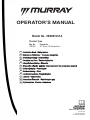 1
1
-
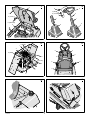 2
2
-
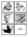 3
3
-
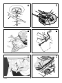 4
4
-
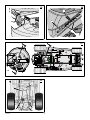 5
5
-
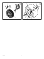 6
6
-
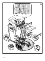 7
7
-
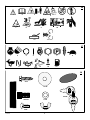 8
8
-
 9
9
-
 10
10
-
 11
11
-
 12
12
-
 13
13
-
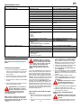 14
14
-
 15
15
-
 16
16
-
 17
17
-
 18
18
-
 19
19
-
 20
20
-
 21
21
-
 22
22
-
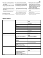 23
23
-
 24
24
-
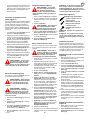 25
25
-
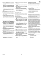 26
26
-
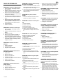 27
27
-
 28
28
-
 29
29
-
 30
30
-
 31
31
-
 32
32
-
 33
33
-
 34
34
-
 35
35
-
 36
36
-
 37
37
-
 38
38
-
 39
39
-
 40
40
-
 41
41
-
 42
42
-
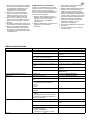 43
43
-
 44
44
-
 45
45
-
 46
46
-
 47
47
-
 48
48
-
 49
49
-
 50
50
-
 51
51
-
 52
52
-
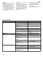 53
53
-
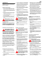 54
54
-
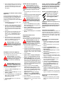 55
55
-
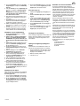 56
56
-
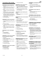 57
57
-
 58
58
-
 59
59
-
 60
60
-
 61
61
-
 62
62
-
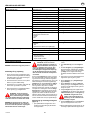 63
63
-
 64
64
-
 65
65
-
 66
66
-
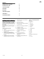 67
67
-
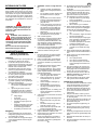 68
68
-
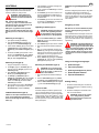 69
69
-
 70
70
-
 71
71
-
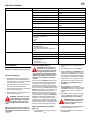 72
72
-
 73
73
-
 74
74
-
 75
75
-
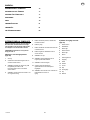 76
76
-
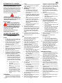 77
77
-
 78
78
-
 79
79
-
 80
80
-
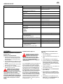 81
81
-
 82
82
-
 83
83
-
 84
84
-
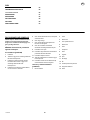 85
85
-
 86
86
-
 87
87
-
 88
88
-
 89
89
-
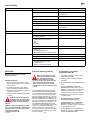 90
90
-
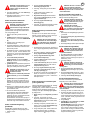 91
91
-
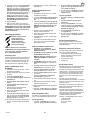 92
92
-
 93
93
-
 94
94
-
 95
95
-
 96
96
-
 97
97
-
 98
98
-
 99
99
-
 100
100
-
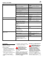 101
101
-
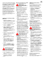 102
102
-
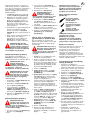 103
103
-
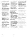 104
104
-
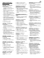 105
105
-
 106
106
-
 107
107
-
 108
108
-
 109
109
-
 110
110
-
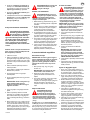 111
111
-
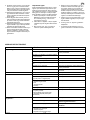 112
112
-
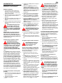 113
113
-
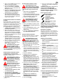 114
114
-
 115
115
-
 116
116
-
 117
117
-
 118
118
-
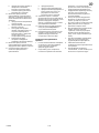 119
119
-
 120
120
-
 121
121
-
 122
122
-
 123
123
-
 124
124
-
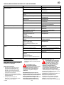 125
125
-
 126
126
-
 127
127
-
 128
128
-
 129
129
-
 130
130
-
 131
131
-
 132
132


Murray 309008X51 Bruksanvisning
- Kategori
- Leksaker
- Typ
- Bruksanvisning
- Denna manual är också lämplig för
på andra språk
- italiano: Murray 309008X51 Manuale del proprietario
- eesti: Murray 309008X51 Omaniku manuaal
- Deutsch: Murray 309008X51 Bedienungsanleitung
- français: Murray 309008X51 Le manuel du propriétaire
- English: Murray 309008X51 Owner's manual
- dansk: Murray 309008X51 Brugervejledning
- Nederlands: Murray 309008X51 de handleiding
Relaterade papper
Andra dokument
-
Simplicity 15HP RIDER WITH A 40" MOWING DECK Användarmanual
-
-
-
STIHL RT 4097.0, RT 4112.0 Användarmanual
-
-
-
AL-KO Combi Unit BF 5002-R Användarmanual
-