
SPS-30MMS
●
●
●
●
●
●
●
●
●
■
■
●
●
●
●
●
●
●
■
Printed in China WG59990
●
●
●
1
2
3
4
5
6
7
8
..
●
1
• 2
•
2
7
•
2
6
8
3
5
4 3
5
•
2
•
618-868
278
64
25
80
320
320
60
© 2005 All rights reserved.
1
1
6
6
2
2
7
3
5
5
3
4
4
8
8
8
8
4
4
5
3
5
3
3 5
3 5
10/4/05, 10:27 PMPage 1

Read this before use
ASSEMBLY
INSTRUCTIONS
SPEAKER STAND
SPS-30MMS
Thank you for selecting the Yamaha SPS-30MMS speaker stand.
YAMAHA ELECTRONICS CORPORATION, USA 6660 ORANGETHORPE AVE., BUENA PARK, CALIF. 90620, U.S.A.
YAMAHA CANADA MUSIC LTD. 135 MILNER AVE., SCARBOROUGH, ONTARIO M1S 3R1, CANADA
YAMAHA ELECTRONIK EUROPA G.m.b.H. SIEMENSSTR. 22-34, 25462 RELLINGEN BEI HAMBURG, GERMANY
YAMAHA ELECTRONIQUE FRANCE S.A. RUE AMBROISE CROIZAT BP70 CROISSY-BEAUBOURG 77312 MARNE-LA-VALLEE CEDEX02, FRANCE
YAMAHA ELECTRONICS (UK) LTD. YAMAHA HOUSE, 200 RICKMANSWORTH ROAD WATFORD, HERTS WD18 7GQ, ENGLAND
YAMAHA SCANDINAVIA A.B. J A WETTERGRENS GATA 1, BOX 30053, 400 43 VÄSTRA FRÖLUNDA, SWEDEN
YAMAHA MUSIC AUSTRALIA PTY, LTD. 17-33 MARKET ST., SOUTH MELBOURNE, 3205 VIC., AUSTRALIA
PRECAUTIONS
● This speaker stand is only for the speaker systems
listed in “USABLE SPEAKERS” below. Do not use
the speakers other than these listed.
● To prevent the speaker from falling, use the screws
and parts provided with the stand.
● To prevent the speaker stand from falling over,
select a location which is flat and stable.
● To avoid accidents resulting from tripping over
loose speaker cables and to prevent the speaker
stand from falling over, fix the speaker cables to the
wall, etc.
● Do not let the children lean on the stand as this
might cause the serious accidents resulting from
the falling over of the speaker stand.
● To prevent the speaker stand from discoloring and
warping, keep the speaker stand away from the stoves
and places where it will be exposed to direct sunlight,
etc.
● Do not attempt to clean the speaker stand with
chemical solvents as this might damage the finish.
Use a clean, dry cloth.
● When moving the speaker and stand, be sure to hold
the support detached from the speaker.
● Secure placement or installation is the owner’s
responsibility. YAMAHA shall not be liable for any
accident caused by improper placement or installation
of speakers.
■ DIMENSIONS
Top view
Front view
● NS-10MMT (NS-10MMTS)
● NX-430P
(the main and rear speakers included in the NS-P430/
NS-P436 speaker package)
● NX-S20
(the front and rear speakers included in the AVX-S20 home
theater sound system)
● NS-M125
● NS-M225
● NX-S30
(the satelite speakers included in the AVX-S30 home theater
sound system)
■ USABLE SPEAKERS
Printed in China WG59990
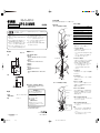
● ASSEMBLY PROCEDURES
Before beginning assembly, check the parts list and make sure all the parts are included.
● ASSEMBLY FIGURE
For speakers with screw holes at the left and right of the
speaker base.
For speakers with screw holes at the front and rear of
the speaker base.
● PARTS LIST
NAME QUANTITY
1 Binding tapping screw (4 x 14 mm) 6
2 Hexagon socket set screw 3 + 1 spare
3 Binding machine screw (4 x 12 mm) 2
4 Washer 2
5 Binding machine screw (6 x 14 mm) 2
6 Pad 4
7 Wrench (hexagonal) 1
8 Gasket 2
.
●
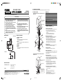
ASSEMBLY PROCEDURES
(You will need a screwdriver for assembly.)
1. Attaching the base and support.
Pass the support through the hole from the bottom of the
base, and fasten the binding tapping screws 1.
• Fix the support so that the holes for the screws comes to
the rear side.
• Do not overtighten the binding tapping screws 1.
Doing so may damage the screws or assembly.
2. Attaching the pole and support.
Insert the pole to the support, and fasten the hexagon
socket set screws 2 into the three holes on the
support using the included wrench 7.
• The line on the pole shows the limit of the stand height.
Do not use the stand pulling out the pole above from this
line. The hexagon socket set screw 2 of the lower side
becomes ineffective and the fixation becomes unstable.
3. Attaching the pads.
Put the pads 6 to the four corners on the bottom of the
base to prevent the stand from moving rickety.
4. Attaching the gaskets.
Put the gaskets 8 to the both sides of the plate.
5. Wiring the speaker cables.
Insert the speaker cables to the hole on the plate, and pass
through the pole. Aligned them to the grooved part on the
bottom of the base.
6. Attaching the speakers.
Line up the holes on the bottom of the speaker and the
center holes on the both sides of the plate. Depending on
the speakers, choose either the binding machine screws 3
(4 x 12mm) or the binding machine screws 5 (6 x 14mm) to
fasten them into the holes.
■ If the speaker has 4mm holes on the bottom:
Fasten the binding machine screws 3 (4 x 12mm) into
the holes with a screwdriver putting the supplied washers
between the screws and the plate.
■ If the speaker has 6mm holes on the bottom:
Fasten the binding machine screws 5 (6x 14mm) into the
holes with a screwdriver.
Note
• After assembly is complete, always loosen the 3
hexagon socket set screws 2 before adjusting
speaker height and direction.
• In order to ensure that the speakers do not fall, always
hold the speakers during the assembly process.
618-868 (24-5/16"-34-3/16")
278 (11")
64
(2-1/2")
25 (1")
80
(3-3/16")
320
(12-5/8")
320
(12-5/8")
60
(2-3/8")
8
Speaker cable
Speaker
8
4
4
5
3
5
3
1
1
6
6
Base
2
Support
2
7
3
5
5
3
4
4
Limit of the
stand height
Pole
8
8
Plate
Speaker cable
Speaker
© 2005 All rights reserved.
■ SPECIFICATIONS
Dimensions (W x H x D) : 320 x 618 – 868 x 320 mm
(12-5/8” x 2 -5/16”
– 34-3/16” x 12-5/8”)
Weight : 2.4 kg (5 lbs. 4 oz.)
Pass the speaker
cable through the
hole on the plate.
Use the binding machine
screw 3 or 5
Use the binding
machine screw
3 or 5
unit: mm(inch)
SPS-30MMS (J/EX) 10/4/05, 10:26 PM1
-
 1
1
-
 2
2


på andra språk
- italiano: Yamaha SPS-30MMS Manuale del proprietario
- čeština: Yamaha SPS-30MMS Návod k obsluze
- español: Yamaha SPS-30MMS El manual del propietario
- Deutsch: Yamaha SPS-30MMS Bedienungsanleitung
- polski: Yamaha SPS-30MMS Instrukcja obsługi
- português: Yamaha SPS-30MMS Manual do proprietário
- français: Yamaha SPS-30MMS Le manuel du propriétaire
- 日本語: Yamaha SPS-30MMS 取扱説明書
- Türkçe: Yamaha SPS-30MMS El kitabı
- English: Yamaha SPS-30MMS Owner's manual
- dansk: Yamaha SPS-30MMS Brugervejledning
- русский: Yamaha SPS-30MMS Инструкция по применению
- suomi: Yamaha SPS-30MMS Omistajan opas
- Nederlands: Yamaha SPS-30MMS de handleiding
- română: Yamaha SPS-30MMS Manualul proprietarului