Yamaha RX-V10MKII Bruksanvisning
- Kategori
- Mottagare
- Typ
- Bruksanvisning

OWNER’S MANUAL
MODE D’EMPLOI
BEDIENUNGSANLEITUNG
BRUKSANVISNING
MANUALE DI ISTRUZIONI
MANUAL DE INSTRUCCIONES
GEBRUIKSAANWIJZING
AV RECEIVER
AMPLI-TUNER AUDIO-VIDEO
RX-V10MK
II
B G R

1. To assure the finest performance, please read this manual
carefully. Keep it in a safe place for future reference.
2. Install this unit in a cool, dry, clean place – away from
windows, heat sources, sources of excessive vibration,
dust, moisture and cold. Avoid sources of humming
(transformers, motors). To prevent fire or electrical shock,
do not expose the unit to rain or water.
3. Never remove the unit cover. Contact your dealer if an
object falls inside the unit.
4. Do not use force on switches, controls or connection wires.
When moving the unit, first disconnect the power plug and
the wires connected to other equipment. Never pull on the
wires themselves.
5. The openings on the unit cover assure proper ventilation of
the unit. If these openings are obstructed, the temperature
inside the unit will rise rapidly. Therefore, avoid placing
objects against these openings, and install the unit in a
well-ventilated area to prevent fire and damage.
<Europe and U.K. models only>
Be sure to allow a space of at least 20 cm behind, 20 cm
on the both sides and 30 cm above the top panel of the
unit to prevent fire and damage.
6. The voltage used must be the same as that specified on
this unit. Using this unit with a higher voltage than
specified is dangerous and may result in fire or other
accidents. YAMAHA will not be held responsible for any
damage resulting from use of this unit with a voltage other
than specified.
7. Always set the VOLUME control to “0” before starting the
audio source play. Increase the volume gradually to an
appropriate level after playback has been started.
8. Do not attempt to clean the unit with chemical solvents;
this might damage the finish. Use a clean, dry cloth.
9. Be sure to read the “TROUBLESHOOTING” section
regarding common operating errors before concluding that
the unit is faulty.
10.When not planning to use this unit for long periods of time,
disconnect the AC power plug from the wall outlet.
11.To prevent lightning damage, disconnect the AC power
plug and antenna cable when there is an electrical storm.
12.Grounding or polarization – Precautions should be taken
so that the grounding or polarization of an appliance is not
defeated.
13.Do not connect audio unit to the AC outlet on the rear
panel if the equipment requires more power than the outlet
is rated to provide.
14.Voltage Selector (General Model only)
The voltage selector on the rear panel of this unit must
be set for your local main voltage BEFORE plugging
into the AC main supply.
Voltages are 110/120/220/240 V AC, 50/60 Hz.
This unit is not disconnected from the AC power source as
long as it is connected to the wall outlet, even if this unit
itself is turned off. This state is called the standby mode.
In this mode, this unit is designed to consume a small
amount of power.
IMPORTANT
Please record the serial number of your unit in the space
below.
Model:
Serial No.:
The serial number is located on the rear of the unit.
Retain this Owner’s Manual in a safe place for future
reference.
WARNING
TO REDUCE THE RISK OF FIRE OR ELECTRIC SHOCK,
DO NOT EXPOSE THIS UNIT TO RAIN OR MOISTURE.
FREQUENCY STEP switch (General Model only)
Because the interstation frequency spacing differs in
different areas, set the FREQUENCY STEP switch (located
at the rear) according to the frequency spacing in your area.
Before setting this switch, disconnect the AC power plug of
this unit from the AC outlet.
For U.K. customers
If the socket outlets in the home are not suitable for the plug
supplied with this appliance, it should be cut off and an
appropriate 3 pin plug fitted. For details, refer to the
instructions described below.
Note: The plug severed from the mains lead must be
destroyed, as a plug with bared flexible cord is hazardous if
engaged in a live socket outlet.
Special Instructions for U.K. Model
IMPORTANT
THE WIRES IN MAINS LEAD ARE COLOURED IN
ACCORDANCE WITH THE FOLLOWING CODE:
Blue: NEUTRAL
Brown: LIVE
As the colours of the wires in the mains lead of this
apparatus may not correspond with the coloured markings
identifying the terminals in your plug, proceed as follows:
The wire which is coloured BLUE must be connected to the
terminal which is marked with the letter N or coloured
BLACK. The wire which is coloured BROWN must be
connected to the terminal which is marked with the letter L
or coloured RED. Making sure that neither core is
connected to the earth terminal of the three pin plug.
2
CAUTION : READ THIS BEFORE OPERATING YOUR UNIT.

3
English
CAUTION ...................................................................2
FEATURES ................................................................4
PROFILE OF THIS UNIT ...........................................5
GETTING STARTED .................................................6
Unpacking ..................................................................6
Opening and closing the front cover ...........................6
Installing batteries in the remote controller ................7
Using the remote controller ........................................7
SPEAKER SET UP ....................................................8
CONNECTIONS .........................................................9
Connecting audio and video components ..................9
Connecting speakers ...............................................12
Connecting antennas ...............................................14
CONTROLS AND THEIR FUNCTIONS ..................16
Front panel ...............................................................16
Remote controller .....................................................18
Display panel ............................................................20
SPEAKER BALANCE ADJUSTMENT.....................21
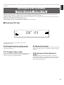
PLAYING AND RECORDING A SOURCE .............24
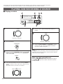
Playing a source .......................................................24
Recording a source to tape (or MD) .........................25
Sound control ...........................................................26
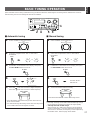
BASIC TUNING OPERATION .................................27
Automatic tuning ......................................................27
Manual tuning ...........................................................27
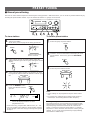
PRESET TUNING ....................................................28
Manual preset tuning ................................................28
Automatic preset tuning ...........................................29
Exchanging preset stations ......................................30
RECEIVING RDS STATIONS
<Europe and U. K. models only>.........................31
Displaying RDS data ................................................31
Selecting your desired program type from
among preset RDS stations (PTY SEEK) ................34
Automatic selection of desired program
when broadcasting starts .........................................35
USING DIGITAL SOUND FIELD PROCESSOR
(DSP) ........................................................................36
Brief overview of Digital Sound Field Programs .......36
Playing a source with an effect of the digital
sound field processor (DSP) ....................................37
TROUBLESHOOTING .............................................40
SPECIFICATIONS ...................................................41
CONTENTS
Thank you for selecting this YAMAHA AV receiver.

4
●
5 Speaker Configuration
(Power Amp. Section)
Main: 45W + 45W (8Ω) RMS Output
Power, 0.04% THD, 20–20,000 Hz
Center: 45W (8Ω) RMS Output
Power, 0.04% THD, 1 kHz
Rear: 15W + 15W (8Ω) RMS Output
Power, 0.3% THD, 1 kHz
●
Digital Sound Field Processor
●
Dolby Pro Logic Surround Decoder
●
Theater-like Sound Experience by the
Combination of Dolby Pro Logic and
YAMAHA DSP Technology (CINEMA DSP)
●
Automatic Input Balance Control for
Dolby Pro Logic Surround
●
Test Tone Generator for Easier Speaker
Balance Adjustment
●
3 Center Channel Modes
(NORMAL/WIDE/PHANTOM)
● 40-Station Random Access Preset Tuning
● Automatic Preset Tuning
● Preset Station Shifting Capability (Preset
Editing)
● IF Count Direct PLL Synthesizer Tuning
System
● On Screen Display Function Helpful in
Controlling This Unit
● 6-Channel Discrete Input Terminals for
Connecting with a Dolby Digital or
Another 5.1-channel Decoder
● Video Signal Input/Output Capability
● SLEEP Timer
● Remote Control Capability
<
Europe and U.K. models only
>
● Multi-Functions for RDS Broadcast
Reception
FEATURES

5
English
PROFILE OF THIS UNIT
You are the proud owner of a Yamaha stereo receiver –an extremely sophisticated audio component. The Digital Sound Field
Processor (DSP) built into this unit takes advantage of Yamaha’s undisputed leadership in the field of digital audio processing to
bring you a whole new world of listening experiences. Follow the instructions in this manual carefully when setting up your system,
and this unit will sonically transform your room into a wide range of listening environments –movie theater, concert hall, and so on.
In addition, you get incredible realism from sources encoded with Dolby Surround using the built-in Dolby Pro Logic Surround
Decoder.
Please read this operation manual carefully and store it in a safe place for later reference.
Digital Sound Field Processing
Technological advances in sound reproduction over the last 30
years have enhanced the listening experience with improved
clarity, precision and power. However, something has still been
missing: The atmosphere and acoustic ambiance of the public
venue. Our Yamaha engineers have extensively researched
the nature of sound acoustics and the way sound reflects
inside a room. We sent these engineers to famous theaters
and concert halls around the world to measure the acoustics of
those venues with sophisticated microphones. The data they
collected is used to recreate these environments in digital
sound fields. Some of these digital sound fields are created
using data measured directly at the original venue; others are
created from combinations of data to form unique
environments for specific purposes.
You can use these sound fields to enhance any source and in
combination with the Dolby Pro Logic Surround technology.
Some are designed especially for music, and some especially
for movies.
Dolby Pro Logic Surround
Dolby Pro Logic Surround has been used in movie theaters
since the mid-seventies. It has also been available in home
entertainment systems since the late eighties and continues to
be a popular format for home theater systems. It uses four
discrete channels and five speakers to reproduce realistic and
dynamic sound effects: two main channels (left and right), a
center channel for dialog, and a rear channel for special sound
effects. The rear channel reproduces sound within a narrow
frequency range.
Most video tapes and laser discs include Dolby Pro Logic
Surround encoding as do many TV and cable broadcasts. The
Dolby Pro Logic Surround decoder built into this unit employs a
digital signal processing system that stabilizes each channel
for even more accurate sound positioning than is available with
standard analog processors.
Manufactured under license from Dolby Laboratories Licensing
Corporation. DOLBY, the double-D symbol and PRO LOGIC
are trademarks of Dolby Laboratories Licensing Corporation.
Dolby Pro Logic Surround + DSP
The Dolby Surround sound system shows its full ability in a
large movie theater, because movie sounds are originally
designed to be reproduced in a large movie theater that uses a
multitude of speakers. Trying to create a sound environment
similar to that of a movie theater in your home is difficult
because of the room size, material inside the walls, number of
speakers, and so on. In other words, your listening room is
very different from a movie theater.
However, Yamaha DSP technology allows you to create nearly
the same sound experience as that of a large movie theater in
your home by compensating for the lack of presence and
dynamics in the listening room with its original digital sound
fields combined with Dolby Surround sound field.
The combination of Dolby Pro Logic Surround and DSP is used
on the sound field program “ PRO LOGIC ENHANCED”.
The YAMAHA “CINEMA DSP” logo indicates these programs that
are created by the combination of Dolby Pro Logic and YAMAHA
DSP technology.
CINEMA DSP

6
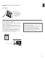
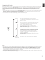
m Opening and closing the front cover
Close the front cover whenever the controls inside the panel are not used.
To open the front cover To close the front cover
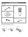
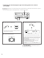
Indoor FM Antenna
AM Loop Antenna
75-ohm/300-ohm antenna adapter (U.K. model only)
Remote Controller
Batteries (size AA, R6, UM-3)
m Unpacking
Carefully remove this unit and accessories from the box. You should find the unit itself and the following accessories.
REC/PAUSE
DIR BDIR A
PLAY
DISC
POWER
/I
VOLUME
PLAY
DVD/LD
2CH/6CH
PRESET
A/B/C/D/E
–+
LEVEL
DELAY/CENTER
/REAR/SWFR
TEST
EFFECT
PROGRAM
PROLOGIC
ENHANCED
–+
SLEEP
TAPE
A/B
ON/OFF
TUNER
CD
PHONO
VCRV-AUX
GETTING STARTED

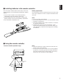
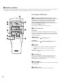
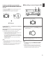
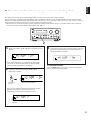
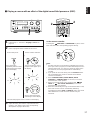
Remote controller operation range
Notes
●
The area between the remote controller and the main unit
must be clear of large obstacles.
●
Do not expose the remote control sensor to strong lighting,
in particular, an inverter type fluorescent lamp. Otherwise,
the remote controller may not work properly. If necessary,
position the main unit away from direct lighting.
7
English
Since the remote controller will be used for many of this unit’s
control operations, you should begin by installing the supplied
batteries.
1.Turn the remote controller over and slide the battery
compartment cover in the direction of the arrow.
2.Insert the batteries (R6, AA, UM-3 type) according to the
polarity markings on the inside of the battery compartment.
3.Close the battery compartment cover.
Battery replacement
If you find that the remote controller must be used closer to the
main unit, the batteries are weak. Replace both batteries with
new ones.
Notes
●
Use only AA, R6, UM-3 batteries.
●
Be sure the polarities are correct. (See the illustration inside
the battery compartment.)
●
Remove the batteries if the remote controller is not used for
an extended period of time.
●
If batteries leak, dispose of them immediately. Avoid
touching the leaked material and contact with clothing, etc.
Clean the battery compartment thoroughly before installing
new batteries.
1
3
2
30°
30°
Remote control
sensor
Within approximately
6 m (19.7 feet)
m Using the remote controller
m Installing batteries in the remote controller

8
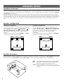
SPEAKER SETUP
Speakers to be used
This unit is designed to provide the best sound-field quality with a 5-speaker configuration. The most effective speakers to use with
this unit are main speakers, rear speakers, and a center speaker. You can do without the center speaker. (Refer to the “4-Speaker
Configuration” shown below.)
The main speakers are used for the main source sound. They could be the speakers from your present stereo system. The rear
speakers are used for the effect and surround sounds, and the center speaker is for the center sounds (dialog etc.) within programs
encoded with Dolby Surround. The center speaker needs to be equal in power to the main speakers, although the rear speakers do
not have to be equal. However, all the speakers should have high enough power handling to accept the maximum output of this
unit.
Speaker configuration
5-Speaker Configuration
This configuration is the most effective and recommended one.
In this configuration, the center speaker is necessary as well as
the rear speakers. If the program PRO LOGIC or
PRO LOGIC ENHANCED is selected, conversations will be
output from the center speaker and the ambience will be
excellent.
• Set the center channel mode to the “NORMAL” or “WIDE”
position. (For details, refer to page 22.)
4-Speaker Configuration
The center speaker is not used in this configuration. If the
program PRO LOGIC or PRO LOGIC ENHANCED is
selected, the center sound is output from the left and the right
main speakers. However, the sound effect of other DSP
programs can be the same as that of the 5-speaker
configuration.
• Be sure to set the center channel mode to the “PHANTOM”
position. (For details, refer to page 22.)
Speaker placement
The recommended speaker configuration, the 5-speaker configuration, will require two speaker pairs: main speakers (your normal
stereo speakers), and rear speakers, plus a center speaker. When you place these speakers, refer to the following.
Main: The position of your present stereo speaker system.
Rear: Behind your listening position, facing slightly inward.
Nearly 1.8m (approx. 6 feet) above the floor.
Center: Precisely between the main speakers. (To avoid
interference with TV sets, use a magnetically shielded
speaker.)
Front L Center Front R
Dialogue
Surround sound
Dialogue
Surround sound
Rear L
Rear R
Front L Front R
Dialogue
Surround sound
Dialogue
Surround sound
Rear L Rear R
Front R
Center
Front L
TV set
Rear R
Rear L
Main L
Main R
Main L
Main R
Main L
Main R

9
English
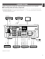
CONNECTIONS
Caution: Plug in this unit and other components after all connections are completed.
m Connecting audio and video components
All connections must be correct, that is to say L (left) to L, R (right) to R, “+” to “+” and “–” to “–”. Also refer to the owner’s manual
for each of your components.
* The output (or input) terminals of YAMAHA components numbered as 1, 3, 4, etc. on the rear panel must be connected to the
same-numbered terminals of this unit.
(* 1), (* 2) : See page 10.
MONITOR
OUT
IN
OUT
IN
PHONO
V
-
AUX
GND
IN CD
OUT
GND
FM
ANT
75Ω
UNBAL
.
AM
ANT
DVD
/LD
1
OUT
3
4
DVD
/LD
I00W MAX.
TOTAL
TAPE
/MD
VCR
VIDEO
SWITCHED
REAR
CENTER
REAR
8
Ω
MIN.
/SPEAKER
8
Ω
MIN./SPEAKER
OUT
SUB
WOOFER
VIDEO
SIGNAL
AUDIO SIGNAL
VCR
SPEAKERS
SUB
WOOFER
MAIN
MAIN
SURROUND
DVD/LD
6CH DISCRT INPUT
AC OUTLETS
CENTER
VIDEO IN
GND
OUTPUT
AUDIO OUT
VIDEO OUT
AUDIO IN
VIDEO IN
AUDIO OUT
VIDEO OUT
OUTPUT
LINE OUT
LINE IN
AUDIO OUT
VIDEO OUT
(Europe model)
To AC outlet
Tape deck,
MD recorder, etc.
Video cassette
recorder
Turntable
LD player,
DVD player, etc.
CD player
TV monitor
TV/Satellite tuner, etc.
(* 2)
(* 1)

10
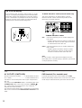
If you connect a VCR, LD player, video monitor, etc. to this
unit, you can display DSP program names and information
about other settings and adjustments on the video monitor
screen. Information is superimposed over the video image.
If there is no image on the monitor, the information will be
displayed over a monochromatic background.
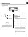
TV MODE PAL/NTSC switch (General model only)
This unit is designed for use with the NTSC and PAL
television formats. Set this switch to the position for the
format your TV monitor employs.
PAL: Set to this position if your TV monitor employs the
PAL format.
* Outputs signals in the PAL format no matter which
format (PAL or NTSC) of video signal is sent from
an external video unit to this unit.
NTSC: Set to this position if your TV monitor employs the
NTSC format.
* Outputs signals in the NTSC format no matter
which format (PAL or NTSC) of video signal is
sent from an external video unit to this unit.
Note
Be sure to input a video signal which employs the same
format that your TV monitor employs, otherwise a picture will
not be played back normally.
ON SCREEN display
MONITOR
OUT
TV
MODE
CD
1
VIDEO
NTSC
PAL
REAR
CENTER
REAR
8
Ω
MIN.
/SPEAKER
OUT
SUB
WOOFER
TV MODE PAL/NTSC switch
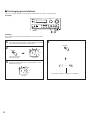
AC OUTLETS (SWITCHED)
(Europe and General models)........... 2 SWITCHED OUTLETS
(U.K. model)......................................... 1 SWITCHED OUTLET
Use these to connect the power cords of your components to
this unit.
The power to the SWITCHED outlets is controlled by this unit’s
STANDBY/ON switch or the remote controller’s POWER /I
key. These outlets will supply power to any component
whenever this unit is turned on.
The maximum power (total power consumption of components)
that can be connected to the SWITCHED AC OUTLETS is 100
watts.
GND terminal (For turntable use)
Connecting the ground wire of the turntable to the GND
terminal will normally minimize hum, but in some cases better
results may be obtained with the ground wire disconnected.
(* 1):
(* 2):

11
English
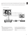
Connecting with 6 channel discrete outputs of a Dolby Digital decoder, DTS decoder or DVD player,
etc.
If you have a Dolby Digital decoder, DTS decoder or a DVD player etc. which incorporates a Dolby Digital decoder, DTS decoder or
MPEG 2 decoder, its 6 channel discrete outputs can be connected to the DVD/LD 6CH DISCRT INPUT terminals of this unit.
Notes
• The LD or DVD player must be also connected to the
DVD/LD AUDIO SIGNAL input terminals of this unit for
playing a source with Dolby Pro Logic Surround decoded or
in 2-channel stereo (or monaural).
• The discrete signals input to this unit cannot be recorded by
a tape deck, MD recorder or VCR. To record a source played
on the LD or DVD player, it must be connected to the
DVD/LD AUDIO/VIDEO SIGNAL input terminals of this unit.
• If you made no connection to the SUBWOOFER input
terminal of this unit or you will not use a subwoofer, you must
make a setting on the Dolby Digital decoder etc. so that
signals at the SUBWOOFER channel are distributed to the
right and left MAIN output terminals of the Dolby Digital
decoder etc.
For details, refer to the owner’s manual for the Dolby Digital
decoder etc.
Dolby Digital decoder
RF
Demodulator
LD player with DOLBY DIGITAL
RF output
An example of connections:
OUTPUT
MAIN CENTER SURROUND
SUBWOOFER
DIGITAL
IN
DOLBY
DIGITAL
RF OUT
VIDEO
OUT
AUDIO
OUT
1
3
MONITOR
OUT
IN
OUT
IN
PHONO
V
-
AUX
GND
IN CD
OUT
GND
FM
ANT
75
Ω
UNBAL
.
AM
ANT
DVD
/LD
OUT
4
DVD
/LD
TAPE
/MD
VCR
VIDEO
OUT
SUB
WOOFER
VIDEO
SIGNAL
AUDIO SIGNAL
VCR
SUB
WOOFER
MAIN
CENTER
SURROUND
DVD/LD
6CH DISCRT INPUT
DOLBY
DIGITAL
RF IN
DIGITAL
OUT

12
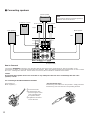
m Connecting speakers
REAR
CENTER
REAR
8
Ω
MIN./SPEAKER
OUT
SUB
WOOFER
SPEAKERS
SUB
WOOFER
MAIN
CENTER
SURROUND
DVD/LD
6CH DISCRT INPUT
8
Ω
MIN.
/SPEAKER
MAIN
Rear speaker Rear speaker
Center speaker
Main speaker
Left
Right
Subwoofer system
Left
Right
(Europe model)
Note
Use speakers with the specified impedance
shown on the rear of this unit.
For connecting to the MAIN SPEAKERS terminals
Red: positive (+)
Black: negative (–)
➀
Loosen the knob.
➁
Insert the bare wire.
[Remove approx. 5mm
(1/4”) insulation from
the speaker wires.]
➂
Tighten the knob and
secure the wire.
<General model only>
Banana Plug connections are also possible. Simply insert the
Banana Plug connector into the corresponding terminal.
1
2
3
How to Connect:
Connect the SPEAKERS terminals to your speakers with the wire of the proper gauge (keep as short as possible). If the
connections are faulty, no sound will be heard from the speakers. Make sure that the polarity of the speaker wires is correct. That is
the + and – markings are observed. If these wires are reversed, the sound will be unnatural and lack bass.
Caution
Do not let the bare speaker wires touch each other or any metal part of this unit. This could damage this unit or the
speakers, or both.
Main speaker

For connecting to the REAR and CENTER SPEAKERS
terminals
Red: positive (+)
Black: negative (–)
➀
Press the tab.
➁
Insert the bare wire.
[Remove approx. 5mm
(1/4”) insulation from
the speaker wires.]
➂
Release the tab and
secure the wire.
13
English
Note on a subwoofer connection:
You may wish to add a subwoofer to reinforce low frequencies
or to output low bass sound from the subwoofer channel when
reproducing discrete signals.
When using a subwoofer, connect the SUBWOOFER OUT
terminal of this unit to the INPUT terminal of the subwoofer
amplifier, and connect the speaker terminals of the subwoofer
amplifier to the subwoofer.
With some subwoofers, including the Yamaha Active Servo
Processing Subwoofer System, the amplifier and subwoofer
are in the same unit. Such a subwoofer needs only the
connection between the SUBWOOFER OUT terminal of this
unit and the INPUT terminal of the subwoofer.
SUBWOOFER OUT terminal
This terminal is for connecting with the input terminal of an
amplifier for driving a subwoofer.
When the input signals to this unit are normal 2-channel
stereo, this terminal outputs low frequencies from the main
and center channels. (The frequency cut-off of this
terminal is at 150 Hz.) When the source equipment
connected to the DVD/LD 6CH DISCRT INPUT terminals
of this unit is selected as the input source, this terminal
outputs signals from the subwoofer channel.
REAR
CENTER
REAR
OUT
SUB
WOOFER
8
Ω
MIN.
/SPEAKER
➁
➂
➀

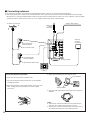
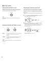
Connecting the AM loop antenna
1.Press the tab and unlock the terminal hole.
2.Connect the AM loop antenna lead wires to the AM ANT
and GND terminals.
3.Return the tab back to the original position to lock the lead
wires. Lightly pull on the lead wires to confirm a good
connection.
4.Attach the loop antenna to the antenna stand.
5.Orient the AM loop antenna so that the best reception is
obtained.
Notes
●
The AM loop antenna should be placed apart from the
main unit. The antenna may be hung on a wall.
●
The AM loop antenna should be kept connected, even if
an outdoor AM antenna is connected to this unit.
14
m Connecting antennas
●
Each antenna should be connected to the designated terminal(s) correctly, as shown in the following figure.
●
Both AM and FM indoor antennas are included with this unit. In general, these antennas will provide sufficient signal strength.
Nevertheless, a properly installed outdoor antenna will give clearer reception than an indoor one. If you experience poor reception
quality only with the indoor antennas, the use of an outdoor antenna may result in improvement.
IN
PHONO
V
-
AUX
GND
IN
OUT
GND
FM
ANT
75
Ω
UNBAL
.
AM
ANT
DVD
/LD
OUT
3
4
TAPE
/MD
VCR
AUDIO SIGNAL
Outdoor FM antenna
Antenna stand
Loop antenna
Outdoor AM antenna
AM loop
antenna
(included)
Ground
75-ohm/300-ohm
antenna adapter
75-ohm/300-ohm
antenna adapter
75-ohm coaxial cable
300-ohm flat ribbon cable
Indoor FM
antenna
(included)
(Europe model)
1
2
3

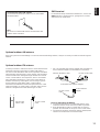
Optional outdoor AM antenna
If this unit is placed in steel buildings or an area far from broadcasting stations, it may be necessary to install an outside long wire
antenna.
15
English
Optional outdoor FM antenna
Consult your dealer or authorized service center about the best
method of selecting and erecting an outdoor FM antenna.
The choice of the flat ribbon cable is also important. Flat ribbon
cable performs well electrically, and is cheaper and somewhat
easier to handle when routing it through windows and around
rooms. Coaxial cable is more expensive, does a much better
job of minimizing interference, is less prone to the effects of
weather and close-by metal objects, and is nearly as good a
signal conductor as flat ribbon cable. Coaxial cable is
somewhat more difficult to install at the point where the cable
enters the building. If coaxial cable is selected, make sure the
antenna is designed to be used with this type of cable.
* Use a 75-ohm/300-ohm antenna adapter (not included) or a
75-ohm antenna adapter (not included) for connections.
300-ohm flat ribbon cable 75-ohm coaxial cable
75-ohm/300-ohm antenna adapter
Notes for FM antenna installation
●
To minimize the influence of automobile ignition noise,
locate the antenna as far from heavy traffic as possible.
●
Keep the flat ribbon cable or coaxial cable as short as
possible. Do not bundle or roll up an excess of the cable.
●
The antenna should be at least two meters (6.6 feet) from
reinforced concrete walls or metal structures.
300-ohm flat
ribbon cable
75-ohm coaxial
cable
75-ohm antenna
adapter
75-ohm coaxial
cable
Connecting the indoor FM antenna
Connect the included indoor antenna to the 75Ω UNBAL.
FM ANT terminal.
Note
Do not use an outdoor FM antenna and the indoor FM
antenna at the same time.
GND terminal
For maximum safety and minimum interference, connect the
GND terminal to a good ground. A good ground is a metal
stake driven into moist earth.

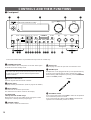
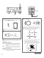
1 STANDBY/ON switch
Press this switch to turn on the power. Press this switch again
to set this unit in the standby mode.
Standby mode
This unit is still using a small amount of power in this mode
in order to be ready to receive infrared-signals from the
remote controller.
2 Remote control sensor
Receives signals from the remote controller.
3 Display panel
Displays a variety of information. (Refer to page 20 for details.)
4 INPUT selector
Turn this knob to select the input source.
The selected source will be shown on the display.
PTY SELECTOR
<Europe and U.K. models only>
When this unit is in the PTY SEEK mode, tuning this control
changes the currently selected program type.
5 VOLUME control
Used to raise or lower the volume level.
6 Front cover
Refer to page 6 on how to open and close the front cover.
7 PHONES jack
Headphones can be plugged into this jack for private listening.
Only the sound signals from the main channels are output.
When listening with headphones privately, set the SPEAKERS
switch to the OFF position.
8 SPEAKERS switch
Press and set this switch inward (ON) to make the all speakers
and a subwoofer produce a sound.
Press and release this switch outward (OFF) to make the all
speakers and a subwoofer produce no sound.
16
CONTROLS AND THEIR FUNCTIONS
m Front panel
SPEAKERS
OFFON
A
/
B
/
C
/
D
/
E
PRESET STATIONS
TUNING
KEY MODE
TUNING
MODE
FM
/
AM
MEMORY PROGRAM
CENTER
MODE
EDIT
AUTO
/
MAN’L MONO MAN’L
/
AUTO FM
BASS TREBLE BALANCE
0
–+
0
–+
LR
INPUT
DVD-LD/ VCR /V-AUX/TAPE•MD/CD / TUNER/ PHONO
VOLUME
0I0
STANDBY/ON
PHONES
NATURAL SOUND AV RECEIVER
RX–V10MK
EON
PTY SEEK
MODE START
PTY SELECTOR
12 3
EF
45
0AB D689 C IJ KGH
L7
6CH/2CH
CINEMA DSP
RDS MODE
/
FREQ
Parts in the shaded areas are provided for Europe and U.K. models only.
PHONES

17
English
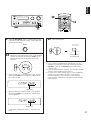
9 RDS MODE/FREQ button
<Europe and U.K. models only>
When an RDS station is received, pressing this button changes
the display mode into the PS mode, PTY mode, RT mode, and
frequency display in turn.
0 PTY SEEK MODE button
<Europe and U.K. models only>
Turns the unit into the PTY SEEK mode.
A PTY SEEK START button
<Europe and U.K. models only>
Begins searching for a station after the desired program type is
selected in the PTY SEEK mode.
B EON button
<Europe and U.K. models only>
Selects the desired program type (NEWS, INFO, AFFAIRS,
SPORT) when you want to call a radio program of the program
type automatically.
C FM/AM button
Press this button to switch the reception band between FM and
AM.
D A/B/C/D/E button
Press this button to select a group (A to E) of preset stations.
E TUNING MODE (AUTO/MAN’L MONO) button
Press this button to switch the tuning mode between automatic
and manual. To select the automatic tuning mode, press this
button so that the “AUTO” indicator is illuminated on the
display. To select the manual tuning mode, press this button so
that the “AUTO” indicator is not illuminated.
F MEMORY (MAN’L/AUTO FM) button
Use this button to enter a station to memory. Refer to the
section “Manual preset tuning” on page 28 for details.
Hold down this button for more than 3 seconds to start
automatic preset tuning. Refer to page 29 for details.
G PRESET STATIONS/TUNING button
This button is used for the PRESET STATIONS function when
“PRESET” is illuminated on the display, and the TUNING
function when “PRESET” is not illuminated. The following
explains these functions in detail.
PRESET STATIONS :
Selects a preset station number (from 1 to 8).
Press the side to select a higher preset station number.
Press the side to select a lower preset station number.
TUNING :
Used for tuning. Press the side to tune in to a higher
frequency, and press the side to tune in to a lower
frequency.
H CENTER MODE button
Selects a center channel output mode (NORMAL, WIDE or
PHANTOM). (For details, refer to page 22.)
I PROGRAM button
When this button is repeatedly pressed, the built-in digital
sound field processor turns on, then the selected DSP program
changes to another program one by one, then the digital sound
field processor turns off, and repeated.
J KEY MODE/EDIT button
Press this button to alternately illuminate and turn off
“PRESET” on the display panel
. This button switches the
function of the PRESET STATIONS/TUNING button.
This button is also used to exchange the places of two preset
stations with each other.
K Tone controls
These controls are effective only for the sound from the main
speakers.
BASS
Used to increase or decrease the low frequency response.
The 0 position produces flat response.
TREBLE
Used to increase or decrease the high frequency response.
The 0 position produces flat response.
L BALANCE control
This knob controls the sound from the main speakers only.
The balance of the output volume to the left and right main
speakers can be adjusted to compensate for sound imbalances
caused by the speaker location or listening room conditions.

18
m Remote controller
The remote controller provided with this unit is designed to control the most commonly used functions. If the CD player or tape deck
is a YAMAHA component with remote control compatibility, this remote controller will also control various functions.
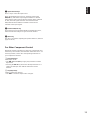
For Control of This Unit
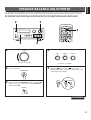
1 DELAY/CENTER/REAR/SWFR and LEVEL +/– keys
Adjust the delay time (DELAY), the center channel output level
(CENTER), the rear channel output level (REAR) and the
output level to the SUBWOOFER OUT terminal (SWFR).
Select the item which you want to adjust by pressing the
DELAY/CENTER/REAR/SWFR key and adjust its time or level
by pressing the LEVEL +/– key.
(For details, refer to pages 23, 26, 38 and 39.)
2 Program selector keys
PROGRAM:
When the built-in digital sound field processor (including the
Dolby Pro Logic Surround decoder) is on, this key changes the
currently selected DSP program each time the right or left side
of this key is pressed.
PROLOGIC:
Directly selects the PRO LOGIC program.
ENHANCED:
Directly selects the PRO LOGIC ENHANCED program.
3 Tuner keys
Control tuners.
+: Press this key to select the next preset station number.
–: Press this key to select the previous preset station
number.
A/B/C/D/E: Selects the group (A to E) of preset station
numbers.
4 SLEEP timer key
This unit is automatically set in the standby mode one hour
after this key is pressed (so that the “SLEEP” indicator is
illuminated). To cancel this function, press this key again so
that the “SLEEP” indicator turns off.
5 POWER /I key
Turns on the power of this unit and sets this unit in the standby
mode alternately.
6 VOLUME +/– keys
Press these keys to increase or decrease the volume.
REC/PAUSE
DIR BDIR A
PLAY
DISC
VOLUME
PLAY
DVD/LD
2CH/6CH
PRESET
A/B/C/D/E
–+
LEVEL
DELAY//CENTER
/REAR/SWFR
TEST
EFFECT
PROGRAM
PROLOGIC
ENHANCED
–+
SLEEP
TAPE
A/B
ON/OFF
TUNER
CD
PHONO
VCR
1
2
3
4
5
2
8
7
9
6
V-AUX
1
POWER
/I

19
English
7 Input selector keys
Press a key to select the input source.
When the DVD/LD input source is selected, pressing the
DVD/LD key switches the input signals between 2 channel
stereo signals and 6 channel discrete signals. When switched
to “6ch”, discrete signals from the unit connected to the
DVD/LD 6CH DISCRT INPUT terminals of this unit are
selected as the input signals.
8 EFFECT ON/OFF key
Press this key to turn on/off the digital sound field processor,
which includes the Dolby Pro Logic Surround decoder.
9 TEST key
This key is used when adjusting the speaker balance. (Refer to
pages 21 to 23.)
For Other Component Control
Identify the remote controller keys with your component’s keys.
If these keys are identical, their functions will be the same. On
each key function, refer to the corresponding instruction on
your component’s manual.
1 Tape deck keys
Control tape decks.
* The DIR A, B and A/B keys apply only to double cassette
tape decks.
* Pressing the DIR A key will reverse the tape direction on a
single cassette tape deck with the automatic reverse
function.
2 CD player keys
Control compact disc players.
* The DISC is used for compact disc changers.

20
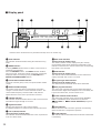
m Display panel
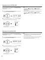
1 AUTO indicator
This indicator will be illuminated during the automatic tuning
mode.
2 MEMO indicator
A flashing MEMO indicator means a station can be saved, as
explained in the following:
Press the MEMORY button. The MEMO indicator will flash
about 5 seconds. While the indicator is flashing, program the
displayed station to memory by using the A/B/C/D/E and
PRESET STATIONS/TUNING buttons.
3 Preset station number indicator
Shows the selected group (A to E) and preset station number
(1 to 8).
4 Multi-information display
This display shows the status of adjustments and setting
changes. Several statuses can be viewed at one time. The
current station frequency and band (AM or FM) will also
appear when the tuner source input mode is selected.
5 STEREO indicator
This indicator will be illuminated when an FM stereo broadcast
with sufficient signal strength is received.
6 Signal-level meter
Indicates the signal level of the received station.
If multipath interference is detected, the indication decreases.
7 PTY H (HOLD) indicator
<Europe and U.K. models only>
This indicator will be illuminated while the search is performed
in the PTY SEEK mode.
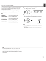
8 RDS mode indicators
<Europe and U.K. models only>
The name(s) of RDS mode(s) employed by the currently
received RDS station will be illuminated. Illumination of the
indicator on the head of a name shows that the corresponding
RDS mode is now selected.
9 EON indicator
<Europe and U.K. models only>
This indicator will be illuminated when an RDS station that
employs the EON data service is received.
0 Program type name indicators
<Europe and U.K. models only>
The name selected in the EON mode will be illuminated.
A DSP program indicators
The name of the selected DSP program will be illuminated
when the built-in digital sound field processor or the Dolby Pro
Logic Surround decoder, or both of them are on.
B Center channel mode indicators
The name of the selected center channel mode (NORMAL,
WIDE or PHANTOM) will be illuminated only when the
PRO LOGIC or PRO LOGIC ENHANCED program is
selected.
C TEST indicator
Flashes when the built-in test tone generator is functioning
(when the test-tone is output from speakers).
D SLEEP indicator
This indicator will be illuminated when the built-in SLEEP timer
is functioning.
12
34 56
789
<AB
CD
TEST
PRESET
MEMO
AUTO
PTY H
PTY
PS RT
EON INFO SPORT
NEWS AFFAIRS
ST
0
MHz
l00
FM
SLEEP
WIDE
NORMAL
PHANTOM
CONCERT
HALL
CONCERT
VIDEO
PRO LOGIC
ENHANCED
ROCK
CONCERT
MONO
MOVIE
Indicators in the shaded areas are provided for Europe and U.K. models only.
Sidan laddas ...
Sidan laddas ...
Sidan laddas ...
Sidan laddas ...
Sidan laddas ...
Sidan laddas ...
Sidan laddas ...
Sidan laddas ...
Sidan laddas ...
Sidan laddas ...
Sidan laddas ...
Sidan laddas ...
Sidan laddas ...
Sidan laddas ...
Sidan laddas ...
Sidan laddas ...
Sidan laddas ...
Sidan laddas ...
Sidan laddas ...
Sidan laddas ...
Sidan laddas ...
Sidan laddas ...
-
 1
1
-
 2
2
-
 3
3
-
 4
4
-
 5
5
-
 6
6
-
 7
7
-
 8
8
-
 9
9
-
 10
10
-
 11
11
-
 12
12
-
 13
13
-
 14
14
-
 15
15
-
 16
16
-
 17
17
-
 18
18
-
 19
19
-
 20
20
-
 21
21
-
 22
22
-
 23
23
-
 24
24
-
 25
25
-
 26
26
-
 27
27
-
 28
28
-
 29
29
-
 30
30
-
 31
31
-
 32
32
-
 33
33
-
 34
34
-
 35
35
-
 36
36
-
 37
37
-
 38
38
-
 39
39
-
 40
40
-
 41
41
-
 42
42


Yamaha RX-V10MKII Bruksanvisning
- Kategori
- Mottagare
- Typ
- Bruksanvisning
på andra språk
- italiano: Yamaha RX-V10MKII Manuale del proprietario
- čeština: Yamaha RX-V10MKII Návod k obsluze
- español: Yamaha RX-V10MKII El manual del propietario
- Deutsch: Yamaha RX-V10MKII Bedienungsanleitung
- polski: Yamaha RX-V10MKII Instrukcja obsługi
- português: Yamaha RX-V10MKII Manual do proprietário
- français: Yamaha RX-V10MKII Le manuel du propriétaire
- Türkçe: Yamaha RX-V10MKII El kitabı
- English: Yamaha RX-V10MKII Owner's manual
- dansk: Yamaha RX-V10MKII Brugervejledning
- русский: Yamaha RX-V10MKII Инструкция по применению
- suomi: Yamaha RX-V10MKII Omistajan opas
- Nederlands: Yamaha RX-V10MKII de handleiding
- română: Yamaha RX-V10MKII Manualul proprietarului
Relaterade papper
-
Yamaha TX-10MKII Bruksanvisning
-
-
-
-
-
-
-
-
-