
T12/T14
EN Original Instructions
DE Übersetzung Der Originalanleitung
FR Traduction Des Instructions Originales
NL Vertaling Van De Originele Instructies
Översättning Av De Ursprungliga Instruktionerna
SE
P.8
P.21
P.35
P.49
P.63

T12/T14
-2-
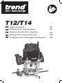
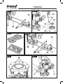
Fig. A
1
T12
T14
T14
2
4
12
16
20
17
15
14
18
19
8
9
11
10
7
3
6
5
13

T12/T14
-3-
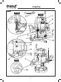
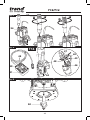
Fig. B1
Fig. B3
Fig. D
Fig. B2
Fig. C
Fig. C
45
6
7
9
35
54
14
16
17
12
18
15
19

T12/T14
-4-
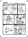
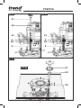
Fig. F
Fig. H
Fig. G
Fig. I
Fig. E 11
10
55
30 31 29
28
27
57
8
9
10
58
60
24
59
25
4
51
5
T12
T14

T12/T14
-5-
1
2
3
4
1
2
3
4
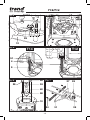
Fig. L
Fig. N
Fig. M
Fig. O
Fig. J Fig. K
10
1028
28
2
53
2
26
10 52
36
37
34
32
33
26
28
29

T12/T14
-6-
Fig. Q
Fig. R
Fig. P
34
38
49
48
47
40
43
46
44
42
41
50
T14

T12/T14
-7-
Fig. S3
61
61
63
63
51 51
4 4
62 62
5 5
64
Fig. S1 Fig. S2
T14

EN - T12/T14
-8-
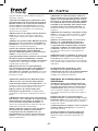
EN - T12 & T14
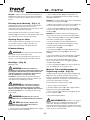
Thank you for purchasing this Trend product, we hope
you enjoy many years of creative and productive use.
Please remember to return your guarantee card within 28
days of purchase.
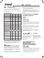
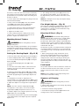
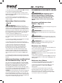
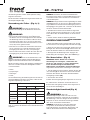
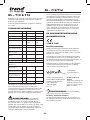
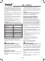
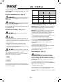
TECHNICAL DATA
T12EL T12E T14E
Voltage V AC 115 230 230
Type 1 1 1
Power input W 2100 2300 2300
No load speed min 1 9000
22000
9000
22000
9000
22000
Router carriage mm 2 column 2 column 2 column
Max cutter diameter
(Portable Router)
mm 50 50 50
Max cutter diameter
in table
mm 50 50 86
Collet size for Europe mm - 12 12
Collet size for UK
and ROI
inch 1/2 1/2 1/2
Weight kg 6.4 6.4 6.5
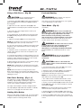
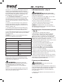
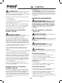
Noise values and vibration values (triax vector sum) according
to EN62841 2 17:
LPA (emission sound
pressure level)
dB(A) 94.2 95.1 95.1
LWA (sound power
level)
dB(A) 105.2 106.1 106.1
K (uncertainty for the
given sound level)
dB(A) 2.5 2.5 2.5
Vibration emission
value ah,hv =
m/s24.1 3.1 3.1
Uncertainty K = m/s20.31 0.31 0.31
The vibration and/or noise emission level given in this
information sheet has been measured in accordance
with a standardised test given in EN62841 and may be
used to compare one tool with another. It may be used
for a preliminary assessment of exposure.
WARNING: The declared vibration and/or
noise emission level represents the main applications
of the tool. However if the tool is used for different
applications, with different accessories or poorly
maintained, the vibration and/or noise emission may
differ. This may significantly increase the exposure level
over the total working period.
An estimation of the level of exposure to vibration and/or
noise should also take into account the times when the
tool is switched off or when it is running but not actually
doing the job. This may significantly reduce the exposure
level over the total working period.
Identify additional safety measures to protect the
operator from the effects of vibration and/or noise such
as: maintain the tool and the accessories, keep the
hands warm (relevant for vibration), organisation of work
patterns.
EC DECLARATION OF CONFORMITY
MACHINERY DIRECTIVE
T12E & T14E
Plunge Router
Trend Tool Technology Ltd declares that these products
described under Technical Data are in compliance with:
2006/42/EC, EN 62841-1:2015 + AC:2015; EN 62841-2-
17:2017.
These products also comply with Directive 2014/30/EU
and 2011/65/EU. For more information, please contact
Trend Tool Technology Ltd at the following address or
refer to the back of the manual.
The undersigned is responsible for compilation of the
technical file and makes this declaration on behalf of
Trend Tool Technology Ltd
Neil McMillan
Technical Director
Trend Tool Technology Ltd
Unit 6 Odhams Trading Estate
St Albans Road, Watford
Herts, WD24 7TR
United Kingdom
01/11/21
UK DECLARATION OF
CONFORMITY
THE SUPPLY OF MACHINERY
(SAFETY) REGULATIONS 2008
T12E & T14E
Plunge Router
Trend Tool Technology Ltd declares that these products
described under “technical data” are in compliance with:
The Supply of Machinery (Safety) Regulations, 2008,
S.I. 2008/1597 (as amended), BS EN 62841-1:2015 +
AC:2015; BS EN 62841- 2-17:2017.
Technical File Contact
Trend Tool Technology Ltd
3rd Floor, Kilmore House,
Park Lane, Spencer Dock,
Dublin 1, Ireland

EN - T12/T14
-9-
tool is switched off or when it is running but not actually
doing the job. This may significantly reduce the exposure
level over the total working period.
Identify additional safety measures to protect the
operator from the effects of vibration and/or noise such
as: maintain the tool and the accessories, keep the
hands warm (relevant for vibration), organisation of work
patterns.
EC DECLARATION OF CONFORMITY
MACHINERY DIRECTIVE
T12E & T14E
Plunge Router
Trend Tool Technology Ltd declares that these products
described under Technical Data are in compliance with:
2006/42/EC, EN 62841-1:2015 + AC:2015; EN 62841-2-
17:2017.
These products also comply with Directive 2014/30/EU
and 2011/65/EU. For more information, please contact
Trend Tool Technology Ltd at the following address or
refer to the back of the manual.
The undersigned is responsible for compilation of the
technical file and makes this declaration on behalf of
Trend Tool Technology Ltd
Neil McMillan
Technical Director
Trend Tool Technology Ltd
Unit 6 Odhams Trading Estate
St Albans Road, Watford
Herts, WD24 7TR
United Kingdom
01/11/21
UK DECLARATION OF
CONFORMITY
THE SUPPLY OF MACHINERY
(SAFETY) REGULATIONS 2008
T12E & T14E
Plunge Router
Trend Tool Technology Ltd declares that these products
described under “technical data” are in compliance with:
The Supply of Machinery (Safety) Regulations, 2008,
S.I. 2008/1597 (as amended), BS EN 62841-1:2015 +
AC:2015; BS EN 62841- 2-17:2017.
Technical File Contact
Trend Tool Technology Ltd
3rd Floor, Kilmore House,
Park Lane, Spencer Dock,
Dublin 1, Ireland
These products conform to the following UK Regulations
Electromagnetic Compatibility Regulations, 2016,
S.I.2016/1091 (as amended).
The Restriction of the Use of Certain Hazardous
Substances in Electrical and Electronic Equipment
Regulations 2012, S.I. 2012/3032 (as amended).
For more information, please contact Trend Tool
Technology Ltd at the following address or refer to the
back of the manual.
The undersigned is responsible for compilation of the
technical file and makes this declaration on behalf of
Trend Tool Technology Ltd .
Neil McMillan
Technical Director
Trend Tool Technology Ltd
Unit 6 Odhams Trading Estate
St Albans Road, Watford
Herts, WD24 7TR
United Kingdom
01/11/21
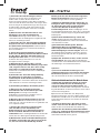
WARNING: To reduce the risk of injury, read
the instruction manual.
Definitions: Safety Guidelines
The definitions below describe the level of severity
for each signal word. Please read the manual and pay
attention to these symbols.
DANGER: Indicates an imminently hazardous
situation which, if not avoided, will result in death or
serious injury.
WARNING: Indicates a potentially hazardous
situation which, if not avoided, could result in death or
serious injury.
CAUTION: Indicates a potentially hazardous
situation which, if not avoided, may result in minor or
moderate injury.
NOTICE: Indicates a practice not related
to personal injury which, if not avoided, may result in
property damage.
Denotes risk of electric shock.
Denotes risk of fire.
GENERAL POWER TOOL SAFETY
WARNINGS
WARNING: Read all safety warnings,
instructions, illustrations and specifications
provided with this power tool. Failure to follow all
instructions listed below may result in electric shock, fire
and/or serious injury.
SAVE ALL WARNINGS AND
INSTRUCTIONS FOR FUTURE
REFERENCE
The term “power tool” in the warnings refers to your
mains- operated (corded) power tool or battery-operated
(cordless) power tool.
1) Work Area Safety
a) Keep work area clean and well lit. Cluttered or
dark areas invite accidents.
b) Do not operate power tools in explosive
atmospheres, such as in the presence of
flammable liquids, gases or dust. Power tools create
sparks which may ignite the dust or fumes.
c) Keep children and bystanders away while
operating a power tool. Distractions can cause you to
lose control.
2) Electrical Safety
a) Power tool plugs must match the outlet. Never
modify the plug in any way. Do not use any
adapter plugs with earthed (grounded) power
tools. Unmodified plugs and matching outlets will
reduce risk of electric shock.
b) Avoid body contact with earthed or grounded
surfaces such as pipes, radiators, ranges and
refrigerators. There is an increased risk of electric
shock if your body is earthed or grounded.
c) Do not expose power tools to rain or wet
conditions. Water entering a power tool will increase
the risk of electric shock.
d) Do not abuse the cord. Never use the cord for
carrying, pulling or unplugging the power tool.
Keep cord away from heat, oil, sharp edges or
moving parts. Damaged or entangled cords increase
the risk of electric shock.
e) When operating a power tool outdoors, use an
extension cord suitable for outdoor use. Use of a
cord suitable for outdoor use reduces the risk of electric
shock.

EN - T12/T14
-10-
f) If operating a power tool in a damp location is
unavoidable, use a residual current device (RCD)
protected supply. Use of an RCD reduces the risk of
electric shock.
3) Personal Safety
a) Stay alert, watch what you are doing and use
common sense when operating a power tool. Do
not use a power tool while you are tired or under
the influence of drugs, alcohol or medication. A
moment of inattention while operating power tools may
result in serious personal injury.
b) Use personal protective equipment. Always
wear eye protection. Protective equipment such as
dust mask, non-skid safety shoes, hard hat or hearing
protection used for appropriate conditions will reduce
personal injuries.
c) Prevent unintentional starting. Ensure the
switch is in the off-position before connecting to
power source and/or battery pack, picking up or
carrying the tool. Carrying power tools with your finger
on the switch or energising power tools that have the
switch on invites accidents.
d) Remove any adjusting key or wrench before
turning the power tool on. A wrench or a key left
attached to a rotating part of the power tool may result in
personal injury.
e) Do not overreach. Keep proper footing and
balance at all times. This enables better control of the
power tool in unexpected situations.
f) Dress properly. Do not wear loose clothing or
jewellery. Keep your hair and clothing away from
moving parts. Loose clothes, jewellery or long hair can
be caught in moving parts.
g) If devices are provided for the connection of
dust extraction and collection facilities, ensure
these are connected and properly used. Use of dust
collection can reduce dust-related hazards.
h) Do not let familiarity gained from frequent use
of tools allow you to become complacent and
ignore tool safety principles. A careless action can
cause severe injury within a fraction of a second.
4) Power Tool Use and Care
a) Do not force the power tool. Use the correct
power tool for your application. The correct power
tool will do the job better and safer at the rate for which
it was designed.
b) Do not use the power tool if the switch does
not turn it on and off. Any power tool that cannot be
controlled with the switch is dangerous and must be
repaired.
c) Disconnect the plug from the powersource and/
or the battery pack, if detachable, from the power
tool before making any adjustments, changing
accessories, or storing power tools. Such preventive
safety measures reduce the risk of starting the power
tool accidentally.
d) Store idle power tools out of the reach of
children and do not allow persons unfamiliar with
the power tool or these instructions to operate the
power tool. Power tools are dangerous in the hands of
untrained users.
e) Maintain power tools and accessories. Check
for misalignment or binding of moving parts,
breakage of parts and any other condition that
may affect the power tool’s operation. If damaged,
have the power tool repaired before use. Many
accidents are caused by poorly maintained power tools.
f) Keep cutting tools sharp and clean. Properly
maintained cutting tools with sharp cutting edges are
less likely to bind and are easier to control.
g) Use the power tool, accessories and tool bits,
etc. in accordance with these instructions, taking
into account the working conditions and the work
to be performed. Use of the power tool for operations
different from those intended could result in a hazardous
situation.
h) Keep handles and grasping surfaces dry, clean
and free from oil and grease. Slippery handles and
grasping surfaces do not allow for safe handling and
control of the tool in unexpected situations.
5) Service
a) Have your power tool serviced by a qualified
repair person using only identical replacement
parts. This will ensure that the safety of the power tool
is maintained.
Safety Instructions for Routers
a) Hold the power tool by insulated gripping
surfaces only, because the cutter may contact
its own cord. Cutting a “live” wire may make exposed
metal parts of the power tool “live” and could give the
operator an electrical shock.
b) Use clamps or another practical way to secure
and support the workpiece to a stable platform.
Holding the work by your hand or against the body
leaves it unstable and may lead to loss of control.
c) Keep handles dry, clean and free from oil and
grease. This will enable better control of the tool.
d) Maintain a firm grip with both hands on the tool
to resist starting torque. Maintain a firm grip on the
tool at all times while operating.
e) Keep hands away from cutting area above and
below the base. Never reach under the workpiece
for any reason. Keep the router base firmly in contact
with the workpiece when cutting.

EN - T12/T14
-11-
f) Never touch the bit immediately after use. It
may be extremely hot.
g) Be sure that the motor has stopped completely
before you lay the router down. If the bit is still
spinning when the tool is laid down, it could cause injury
or damage.
h) Be sure that the router bit is clear of the
workpiece before starting the motor. If the bit is
in contact with the workpiece when the motor starts, it
could make the router jump, causing damage or injury.
i) The permitted speed of the cutting bit must be
at least equal to the maximum speed marked on
the power tool. If cutting bits run faster than their rated
speed, they may break and fly off.
j) Always follow the bit manufacturer’s speed
recommendations as some bit designs require
specific speeds for safety or performance. If you
are unsure of the proper speed or are experiencing any
type of problem, contact the bit manufacturer.
k) Do not use cutters larger than 50 mm (2”)
unless the router is fitted in a router table.
Do not use cutters larger than 86 mm (3 3/8”) in
this tool.
RESIDUAL RISKS
WARNING: We recommend the
use of a residual current device with
a residual current rating of 30mA or
less.
In spite of the application of the relevant safety
regulations and the implementation of safety devices,
certain residual risks cannot be avoided. These are:
• Impairment of hearing.
• Risk of personal injury due to flying particles.
• Risk of burns due to accessories becoming hot during
operation.
• Risk of personal injury due to prolonged use.
SAVE THESE INSTRUCTIONS
Electrical Safety
The electric motor has been designed for one voltage
only. Always check that the power supply corresponds to
the voltage on the rating plate.
Your tool is double insulated in accordance with
EN62841; therefore no earth wire is required.
115V machines are intended to be used with a safety
transformer manufactured to BS EN 61558 and
BS 4343. Never work without this transformer in place.
If the supply cord is damaged, it must be replaced only
by Trend Tool Technology Ltd or an authorised service
organisation.
Mains Plug Replacement (U.K. & Ireland Only)
If a new mains plug needs to be fitted:
• Safely dispose of the old plug.
• Connect the brown lead to the live terminal in the plug.
• Connect the blue lead to the neutral terminal.
WARNING: No connection is to be made to
the earth terminal. Follow the fitting instructions supplied
with good quality plugs. Recommended fuse for 230V
U.K. plug: 13 A.
Fitting a Mains Plug to 115 V Units
(U.K. and Ireland Only)
• The plug fitted should comply with BS EN 60309
(BS4343), 32 Amps.
WARNING: Always ensure that the cable
clamp is correctly and securely fitted to the sheath of
the cable.
Using an Extension Cable
An extension cord should not be used unless absolutely
if an extension cable is required, use an approved 3–core
extension cable suitable for the power input of this tool
(see Technical Data).The minimum conductor size is
1.5 mm2; the maximum length is 30m.
When using a cable reel, always unwind the cable
completely.
PACKAGE CONTENT
1 x Router
1 x Collet 1/2” UK & ROI (12mm EU)
1 x Parallel fence
2 x Guide rods
1 x Guide bush (30mm)
1 x 22 mm wrench
1 x SA Dust extraction tube
1 x Remote Switch Box (T14 only)
1 x Instruction manual
1 x Fine height adjuster (T14 only)
• Check for damage to the tool, parts or accessories
which may have occurred during transport.
• Take the time to thoroughly read and understand this
manual prior to operation.
MARKINGS ON TOOL
The following pictograms are shown on the tool:
Read instruction manual before use.

EN - T12/T14
-12-
Wear ear protection.
Wear eye protection.
Visible radiation. Do not stare into light.
Date Code Position - (Fig. A)
The date code (56) , which also includes the year of
manufacture, is printed into the housing.
Example:
2021 XX XX
Year and Week of Manufacture
Description - (Fig. A)
WARNING: Never modify the power tool or
any part of it. Damage or personal injury could result.
1. Speed control wheel
2. Main handles
3. On/off trigger switch
4. Thumb wheel
5. Height stop rod
6. Plunge lock lever
7. Quick release button
8. Spindle lock button
9. Collet assembly
10. Base plate
11. Multiple position turret stop
12. Depth stop bar
13. 22 mm wrench
14. Quick zero reset ring
15. Quick height adjuster lock
16. Quick height adjuster
17. Pointer
18. Fine adjuster
19. Fine zero reset ring
20. Lock on button switch
Intended Use
The T12 and T14 routers have been designed for
professional heavy duty routing of wood, wood based
materials and plastics.
These routers are intended for routing grooves, edges,
profiles and slots as well as copy routing.
DO NOT use under wet conditions or in the presence of
flammable liquids or gases.
The T12 and T14 are professional power tools.
The T14 is designed so that it can be installed into a
router table. The router may only be installed in tables
that meet the legal safety requirements for router tables.
DO NOT let children come into contact with the tool.
Supervision is required when inexperienced operators
use this tool.
• Young children and the infirm. This appliance is not
intended for use by young children or infirm persons
without supervision.
• This product is not intended for use by persons
(including children) suffering from diminished physical,
sensory or mental abilities; lack of experience,
knowledge or skills unless they are supervised by a
person responsible for their safety. Children should
never be left alone with this product.
CAUTION: Before operating any of the
controls, read the following sections.
Plunge Lock Lever - (Fig. B)
The plunge lock lever (6) allows you to stop the working
bit at a specified height.
1. Press down the plunge lock lever (6) until you hear an
audible “Click” when you want to lower the router bit into
the workpiece.
2. You can lower the unit until it reaches your preset
stop.
3. To lock the tool in place along its vertical travel, press
quick release button (7).
Collets - (Fig. C)
WARNING: Projectile hazard. Only use bits
with shanks that match the installed collet. Smaller
shank bits will not be secure and could become loose
during operation.
CAUTION: Never tighten the collet without
first installing a router bit in it. Tightening an empty collet,
even by hand, can damage the collet.
A collet is included with this router.
• 12 mm: Europe
• 1/2”: UK & Eire
1. To change collets (35), unscrew the collet assembly
(9)
2. Sharply pull the old collet out of the collet nut (45) and
insert the new collet (35).
3. Push firmly so that the new collet snaps past the
retainer spring in the collet nut.
Multiple Position Turret Stop - (Fig. E)
WARNING: Do not change the turret stop
while the router is running. This will place your hands too
near the cutter head.
The turret stop (11) limits the downward distance that
the tool can be plunged. It consists of three screws of

EN - T12/T14
-13-
different lengths that serve to define the depth of cut by
limiting the travel of the depth stop bar (12).
1. Routing depth can be set by selecting the screw of the
appropriate length on the turret.
2. The turret is rotatable with detent stops to properly
align the screws.
3. It is the interaction of the depth stop bar and the turret
stop that determine the routing depth.
4. If none of the provided screws seems close to the
desired height each can be adjusted by loosening the
hex nut at the bottom and then turning the screw either
in or out to make it the proper length. After adjusting this
screw be sure to tighten the hex nut at the bottom with
the an 8 mm wrench (55).
5. Refer to section Setting the Routing Depth for
instructions on how to use the turret stop in an actual
operation.
Height Stop Rod and Height Stop
Thumb Wheel - (Fig. G & Ga)
T12 Height Stop Rod and Height Stop Thumb Wheel
(Fig. G)
The height stop rod (5) and thumb wheel (4) limit how
high the unit can travel up the rails. The system is
adjustable to limit the rise of the plunge regardless of
the position of the plunge release lever to full up where
the bottom of the collet is 80 mm (3 5/32”) above the
workpiece.
NOTE: It is easier to move the height stop thumb wheel
UP if the plunge release lever is locked and easier to
move the thumb wheel down if the unit is first moved
down by releasing the plunge release lever and then
tightening it.
ASSEMBLY AND ADJUSTMENTS
WARNING: To reduce the risk of serious
personal injury, turn tool off and disconnect
tool from power source before making any
adjustments or removing/ installing attachments
or accessories. An accidental start-up can cause
injury.
Installing and Removing a Cutter
- (Fig. C, F)
WARNING: Do not tighten the collet without
a cutter fitted.
WARNING: Always use cutters with shanks
which match the diameter of the collet.
WARNING: Do not use cutters larger than 50
mm (2”) unless the router is fitted in a router table.
CAUTION: Care should be taken when
removing cutter to avoid cuts to fingers.
Installing a Cutter
1. Insert at least three fourths of the shank length of the
cutter into the collet assembly (9).
2. Press the spindle lock (8) forward until the router
spindle is locked.
NOTE: You may need to turn the spindle slightly to
engage it.
3. Turn the collet nut (45) counter clockwise with the
supplied 22 mm wrench (13) to tighten it.
Removing a Cutter
1. Press the spindle lock button (8) forward until the
router spindle is lock.
2. Turn the collet nut (9) clockwise with the supplied 22
mm wrench (13) to loosen.
3. Keep turning the wrench until the collet nut tightens
and then loosens again. This is the fail safe mechanism
releasing the collet.
4. The cutter should now slide out.
NOTE: Each time you finish using a cutter, remove it and
store it in a safe place.
Fine Height Adjuster - (Fig. A, D, E)
CAUTION: Ensure that the plunge locking
lever is unlocked. Never use unnecessary force to rotate
the fine height adjuster mechanism.
CAUTION: DO NOT remove the screw on
hex nuts.
The fine height adjuster can be used in portable mode or
when the router is held inside a table.
Adjusting the Depth of Cut
- (Fig. A, D, E)
Your router is equipped with a high precision depth
adjustment system including a zero reset ring for both
the quick height adjuster and the fine height adjuster.
Quick adjustment Using the
graduation with Zero Reset Ring
1. Loosen the depth stop quick height adjuster lock (15).

EN - T12/T14
-14-
2. Unlock the plunge limiter by pushing the release lever
(6) down.
3. Lower the router carriage until the cutter is in contact
with the workpiece.
4. Press the quick locking button (7).
5. Set the quick height adjuster (16) to zero and reset
the fine adjust reset ring (19) to zero. The depth stop bar
(12) must be in contact with the turret stop (11).
6. Adjust the depth of cut using the quick height adjuster
(16) and the corresponding graduation. The adjusted
depth of cut is indicated by the pointer (17).
7.Tighten the quick height adjuster lock (15).
Fine Adjustment
When not using a depth template, or if the depth of cut
needs readjustment, it is recommended to use the fine
height adjuster (18).
1. Adjust the depth of cut as described in Adjusting the
Depth of Cut.
2. Set the fine height adjuster to zero using the fine zero
reset ring (19).
3. Rotate the fine height adjuster (18) to the required
position: one turn corresponds to approximately 1 mm
and 1 mark to 0.1 mm.
Fitting Template Guide Bush and
Inner Plate - (Fig. H)
The routers have a unique built-in line up system for the
template guide bush. This system ensures that the guide
bush is exactly concentric to the router cutter to ensure
accurate work.
1. Turn the router upside down.
2. Fit inner plate (58) into the recess in the router base
plate (10). For T12 the bushes on the inner plate must be
towards the router motor. For T14 the raised side of the
inner plate must be away from router base. Loosely fit
the two pan head machine screws (59) through the inner
plate and into the tapped holes. DO NOT TIGHTEN
SCREWS.
3. Fit the 30mm template guide bush (24) to the inner
plate (58). Fit guide bush with the two M5 countersink
machine screws (25). Tighten these screws.
4. The line-up pin (60) is stepped for 12mm and 1/2”
collet (9) sizes. (For the 1/2” collet simply push the line-
up pin further down into the 1/2” collet).
5. Fit line up pin (60) into the 1/2” collet (9) (or 12mm
depending on the size fitted) in the router, lightly tighten
collet nut to hold the line up pin (60).
6. Release plunge lever and gently depress base until
line up pin (60) projects through the 30mm guide bush
(24).
7. Once in line, tighten the pan head machine screws
(59) with a flat screwdriver.
Fitting the Parallel Fence - (Fig. I, J)
1. Fit the guide rod (26) to the router base (10).
2. Slide the parallel fence (27) over the rods.
3. Tighten the wing bolts (28) temporarily.
Adjusting the Parallel Fence -
- (Fig. A, I, J)
1. Draw a cutting line on the material.
2. Lower the router carriage until the cutter is in contact
with the workpiece.
3. Push quick release button (7) and limit the carriage
return using the thumb wheel (4).
4. Position the router on the cutting line.
5. Slide the parallel fence (27) against the workpiece and
tighten the wing bolts (28).
6. Adjust the parallel fence using the fine adjustment
knob (29). The outer cutting edge of the cutter must
coincide with the cutting line.
7. If required, loosen the screws (30) and adjust the
strips (31) to obtain the desired guiding length.
Dust Extraction - (Fig. A, K, P)
Dust from materials such as lead containing coatings
and some wood types, can be harmful to one’s health.
Breathing in the dust can cause allergic reactions and/or
lead to respiratory infections of the user or bystanders.
Certain dust, such as oak or beech dust, is considered
carcinogenic, especially in connection with wood
treatment additives.
Observe the relevant regulations in your country for the
materials to be worked.
The vacuum cleaner must be suitable for the material
being worked.
When vacuuming dry dust that is especially detrimental
to health or carcinogenic, use dust class M vacuum
cleaner.
Connecting Dust Extraction Adaptor
- (Fig. K)
The dust extraction adaptor consists of a main section
(32), a cover (33), an extraction tube adaptor (34) , one
extraction tube screw (37), two base screws (52) and
two nuts (36) .
1. Slide the cover (33) onto the main section (32) until it
clicks into place.
2. Place the main section (32) on the base and secure
with two screws (52) and nuts (36).

EN - T12/T14
-15-
3. Remove screw (37) from the top of the router and use
this screw to assemble the extraction tube adaptor (34)
to the router.
Connecting Dust Extractor Hose
- (Fig. P)
WARNING: Risk of dust inhalation. To reduce
the risk of personal injury, ALWAYS wear an approved
dust mask.
WARNING: ALWAYS use a vacuum extractor
designed in compliance with the applicable directives
regarding dust emission when sawing wood. Vacuum
hoses of most common vacuum cleaners will fit directly
into the dust extraction outlet.
Connect a dust extractor hose (38) to the extraction
tube adaptor (34).
A dust extraction tube adaptor (34) is supplied with your
tool. Vacuum hoses on most vacuum extractors will fit
directly into the dust extraction spout.
NOTE: When using dust extraction, be sure that the
dust extractor is out of the way and secure so that it
will not tip over or interfere with the router or workpiece.
The dust extractor hose and power cord must also be
positioned so that they do not interfere with the router or
workpiece. If the dust extractor or dust extractor hose
cannot be positioned properly, it should be removed.
OPERATION
Instructions for Use
WARNING: Always observe the safety
instructions and applicable regulations.
WARNING: To reduce the risk of serious
personal injury, turn tool off and disconnect
tool from power source before making any
adjustments or removing/ installing attachments
or accessories. An accidental start-up can cause
injury.
Proper Hand Position - (Fig. O)
WARNING: To reduce the risk of serious
personal injury,
ALWAYS use proper hand position as shown
WARNING: To reduce the risk of serious
personal injury,
ALWAYS hold securely in anticipation of a sudden
reaction.
Proper hand position requires both hands on the main
handles (2).
Using the Router - (Fig. A, L)
CAUTION: Turn the router on before plunging
the cutter head into the workpiece.
CAUTION:
• Excessive cutting may cause overload of the motor or
difficulty in controlling the tool, the depth of cut should
not be more than 15 mm (19/32”) at a pass when
cutting grooves with a 8 mm (5/16”) diameter bit.
• When cutting grooves with a 20 mm (25/32”) diamter
bit, the depth of cut should not be more than 5 mm
(3/16”) at a pass.
• For extra deep grooving, make two or three passes
with progressively deeper bit settings.
CAUTION: After long periods of working at
low speeds, allow the machine to cool down by running
it for three minutes at maximum speed, with no load.
All common routing tasks can be performed with the
plunge cut router on all types of wood and plastic:
• Grooving
• Rebating
• Recessing
• Veining
• Profiling
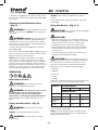
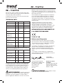
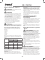
To prevent overload of the tool by using the wrong speed
selection, follow the recommended settings below:
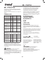
MATERIAL CUTTER DIAMETER
10 – 30 mm 30 – 50 mm 50 – 86* mm
SPEED SELECTION
Hardwood 7 - 5 6 - 2 5 - 2
Softwood 7 - 6 7 - 5 5 - 2
Chipboard
Faced
7 - 6 7 - 4 n / a
Plastic 7 - 5 7 - 4 n / a
* Do not use cutters larger than 50 mm (2”) unless the
router is fitted in a router table.
NOTE: Only carbide tipped cutters should be used on
panels faced with plastic laminates. The hard laminates
will quickly dull steel cutters.

EN - T12/T14
-16-
NOTE: For better plunge sliding movement, frequently
clean the columns of dust or debris. If the plunging
movement is not moving as smooth as desired, lubricate
the columns with a dry Teflon lubricant.
1. After setting the cutting depth as described, locate the
router such that the bit is directly over the place you will
be cutting.
2. With the router running, lower the unit smoothly down
into the workpiece. DO NOT JAM THE ROUTER
DOWN.
3. When the tool reaches the pre set depth, push the
quick release button (7) to lock.
4. When you have finished routing, push the plunge
lock lever (6) to unlock and let the spring lift the router
directly out of the workpiece.
5. Always feed the router opposite to the direction in
which the cutter is rotating. Refer to Fig. L.
On/Off Trigger Switch - (Fig. A)
WARNING: To reduce the risk of serious
personal injury, turn unit off and disconnect it from power
source before making any adjustments or removing/
installing attachments or accessories. An accidental
start-up can cause injury.
1. To turn the unit on, squeeze the on/off trigger switch
(3). Continue to squeeze the trigger switch or press the
lock on button switch (20) for continuous running.
2. To turn the unit off:
a. If lock on trigger is engage, release the lock on button
by squeezing and releasing trigger.
b. If the lock on switch is not engaged, fully release the
trigger.
Variable Speed Dial - (Fig. A)
WARNING: If the speed control ceases
to operate, or is intermittent, stop using the tool
immediately. Please contact Trend Tool Technology Ltd
or authorized service facility for repair.
NOTICE: The router is equipped with electronics to
monitor and maintain the speed of the tool while cutting.
In low and medium speed operation, the speed control
prevents the motor speed from decreasing. If you expect
to hear a speed change and continue to load the motor,
you could damage the motor by overheating. Reduce
the depth of cut and/or slow the feed rate to prevent tool
damage.
Refer to the Speed Selection Chart to choose a router
speed. Turn the speed dial (1) to control router speed.
The speed is variable from 9000 to 22000 rpm using the
speed dial (1).
1. Turn the speed dial to the required position. The dial is
numbered from 1 –7 and corresponds to router speeds
of 9000 rpm to 22000 rpm.
2. Use the slower settings for large diameter cutters and
the faster settings for small diameter cutters.
3. The correct setting will also depend on the density of
the material, depth of cut and feed speed of the router.
NOTE: A noticeable loss of motor rpm means motor
overload
SPEED SELECTION CHART
DIAL SETTING APPROXIMATE RPM
1 9000
2 11000
3 13000
4 15000
5 18000
6 20000
7 22000
The speeds in this chart are approximate and are for
reference only. Your router may not produce the exact
speed listed for the dial setting.
WARNING: Always follow the bit
manufacturer’s speed recommendations as some
bit designs require specific speeds for safety or
performance.
If you are unsure of the proper speed or are experiencing
any type of problem, contact the bit manufacturer.
LED Worklight - (Fig. F)
CAUTION: Do not stare into worklight.
Serious eye injury could result.
Two LED worklights (57) are located next to the collet
assembly (9).
1. The worklights (57) will constantly illuminate when the
router is connected to the mains power supply.
2. To switch off the worklights the router must be
disconnected from mains power supply.
NOTE: The worklight is for lighting the immediate work
surface and is not intended to be used as a flashlight.
Setting Plunge Lock System - (Fig. B)
The plunge is fully automatically locking for all cuts. For
heavy cut operations, ensure to push the lever towards
the tool body. The plunge lock lever (6) position is set at

EN - T12/T14
-17-
the factory so the lever does not touch the motor body,
if the plunge lock lever begins to hit the body when the
quick release lever is pushed, readjust the locking lever
position as follows:
1. Push in quick release button (7). The plunge lever lock
will unlock automatically.
2. Using a Torx 20 star bit (39), loosen the shoulder
screw (54) on the plunge lock lever (6) with six
counterclockwise turns. Do not fully remove.
3. Lift the plunge lock lever, rotate and reposition the
plunge lock lever at position 2 (at eleven o’clock).
4. Tighten the shoulder screw.
5. If after setting to position 2 sliding is not correct,
repeat steps 1 to 3 and reposition the lock lever at
position 1. Tighten the shoulder screw.
Moulding Natural Timbers
WARNING: When routing always lock the
plunge locking lever.
When edge moulding natural timbers, always mould the
end grain first, followed by the long grain. This ensures
that if there is breakout, it will be removed when the long
grain is routed.
Setting the Routing Depth - (Fig. D, E)
1. Place the router with cutter fitted on to the workpiece.
2. Set the multiple position turret stop (11) as required.
3. Loosen the knob quick adjustment (15) securing the
depth stop (12).
4. Push down the plunging lock lever (6) to start
plunging.
5. Lower the router slowly until the cutter touches the
workpiece and secure it in place by pushing quick
release button (7).
6. Rotate the quick height adjuster (16) until the depth
stop bar (12) touches multiple turret stop (13) . Secure
in position by tightening the quick height adjuster lock
(15).
7. If the depth of cut needs re adjustment, it is
recommended to use quick depth adjuster (16) for gross
settings, or the fine height adjuster for accurate settings.
8. Adjust the depth of cut using the fine height adjuster
(18)
NOTE: : One turn of the fine height adjuster (18)
corresponds to 1 mm (3/64”), one turn of the quick
height adjuster (15) corresponds to 40 mm (1 1/2”)
9. Read the depth of cut using the quick zero reset ring
(14) and fine zero reset ring (19).
10. The distance between the top of the revolving depth
stop and the bottom of the depth stop is the required
depth of cut.
11. The rotating turret stop screws (11) can be used
for setting up to three depths of cut. The height can
be adjusted using a flat screwdriver and a 8mm (5/16”)
wrench.
NOTE: By rotating the turret stop, three depth settings
can be quickly made.
Fine Height Adjuster - (Fig. D)
This router has a built in fine height adjuster. This should
be used when fine height adjustment of the cutter is
required. This is especially recommended when using
dovetail jigs or router tables.
Direction Of Feed - (Fig. L)
WARNING: Avoid climb-cutting (cutting in
direction opposite than shown in Fig. L). Climb-cutting
increases the chance for loss of control resulting in
possible injury. When climb-cutting is required (backing
around a corner), exercise extreme caution to maintain
control of router. Make smaller cuts and remove minimal
material with each pass.
The direction of feed is very important when routing and
can make the difference between a successful job and
a ruined project. Fig. L show proper direction of feed for
most cuts.
1. When routing along an edge, the direction of the
router travel should be against that of the rotation of
the cutter. This will create the correct cutting action
and prevent the cutter from snatching. It will also pull
the router towards the workpiece and the side fence or
guide bearing will be less likely to wander from the edge
of the workpiece.
Feed Speed
The speed at which the cutter is fed into the wood must
not be too fast that the motor slows down, or too slow
that the cutter leaves burn marks on the face of the
wood.
NOTE: Practice judging the speed by listening to the
sound of the motor when routing.
Sequence of Plunging
WARNING: When routing always lock the
plunge locking lever.
1. Plunge down and lock the motor carriage, by pushing
quick release button (7).
2. Perform the desired routing operation.
3. Push down the plunge lock lever (6) and the motor
carriage returns to the normal position.

EN - T12/T14
-18-
Using a Side Fence - (Fig. M)
CAUTION: Ensure working position is
comfortable and at a suitable working height.
1. Ensure the wing bolts (28) are fully released. Slide the
guide rods (26) into the routing base (10) and tighten
the wing bolts.
2. Adjust the fence fine adjustment knob (29) to the
required distance and clamp in place with the wing bolts
(28).
3. Then lower the cutter height until the cutter is just
above the workpiece.
4. Fine adjustments are possible by loosening the wing
bolt (28) and adjusting the side fence fine adjustment
knob (29).
5. Tighten the wing bolt (28) to secure the position.
NOTE: One revolution of the side fence fine adjustment
knob (29) equals 3/64” (1.0 mm) of side feed.
6. Lower the cutter onto the workpiece and set the cutter
height by to the required distance. Refer to Setting the
Router Depth.
7. Switch the router on and after the cutter reaches full
speed, gently lower the cutter into the workpiece and
lock the plunge.
8. Feed along the workpiece, keeping sideways pressure
to ensure the side fence does not wander away from the
workpiece edge and downward pressure on the inside
hand to prevent the router from tipping.
9. When finished, raise the router, secure with the plunge
locking lever (6) and switch the router off.
NOTE: When starting the cut, keep the pressure on the
front cheek until the back cheek contacts the workpiece
edge.
NOTE: At the end of the cut, keep pressure on the
back cheek until the cut is finished. This will prevent the
router cutter swinging in at the end of the workpiece and
nipping the corner.
Side Fence Routing - (Fig. I, J)
The side fence is used to guide the router when
moulding, edge profiling or rebating the edge of a
workpiece or when routing grooves and slots in the
center of the workpiece, parallel to the edge.
The edge of the workpiece must be straight and true.
The strips (31) are adjustable and should be set ideally
with a 1/8” (3 mm) gap each side of the cutter.
Guiding Off a Batten
Where an edge guide cannot be used, it is also possible
to guide the router along a batten clamped across the
workpiece (with an overhang at both ends).
Freehand Routing
WARNING: Make shallow cuts only! Use
cutters with a max. diameter of 12mm.
Your router can also be used without any sort of guide,
e.g. for signwriting or creative work.
Table Mode - (Fig. Q)
(T14 ONLY)
WARNING: Before T14 is installed into
the router table, check that the router table meets
all of the legal safety requirements for router
tables. Read all safety warnings, instructions,
and specifications provided with the router table.
Failure to follow all instructions and safety rules may
result in electric shock, fire and/or serious injury.
WARNING: To reduce the risk of serious
personal injury, turn unit off and disconnect
it from power source before making any
adjustments or removing/ installing attachments
or accessories. An accidental start-up can cause
injury.
WARNING: Do not use the T14EK as
a handheld router if the power switch box is
connected.
CAUTION: If there is dust inside the
power switch socket, clean it out before using the
power switch box.
1. To connect the power switch box (41) to the router,
disconnect the tool from its power source.
2. Attach the power switch box (41) to the workbench
in a position easily accessible by hand and where
unintentional switching on is prevented.
NOTE: The external switch can be secured to the router
table with the four mounting holes (42).
3. The cable must be installed and fastened in such a
way that it cannot be squeezed or touch sharp edges.
4. Push in on the lock button (43) located on the left side
handle (44) with a pen or a small screwdriver to unlock
the handle cap (40).
NOTE: If there is dust inside the power switch socket,
clean it out before using the power switch box.
5. Keep pushing the lock button (43) in and rotate the
handle cap (40) to access the power switch socket (46).
6. Ensure the paddle switch of the power switch box is
in the off position before connecting to the power switch
socket.

EN - T12/T14
-19-
7. Connect power switch box plug (47) to the power
switch socket (46).
8. Thread the ring nut (48) of power switch box plug
(47) to the power switch socket (46) to lock it securely
in place.
9. Attach the plunge router under the workbench, as
required per your application or the instruction for the
router table switch box (41).
10. Plug the tool back into its power source. The router
can now switched on and off by acting on paddle (49)
on the power
11. Pull out the paddle (49) to start the tool and push in
the paddle to switch it off.
Fitting the T14 Fine Height Adjuster
- (Fig. S1)
The fine height adjuster (Quick Raiser) (61) for the T14
can be used portably or when the router is held inverted
in a table. If a suitable size access hole is drilled into
the router table top, the height adjustment can also be
adjusted from above the table top.
To set up for fine height adjustment:
1. Plunge router and lock lever down.
2. Rotate the knurled nut (4) down the stud until it is
close to the router casting forks (62).
3. Align the base of the knurled nut (4) so that it will
locate in the forks (62).
4. Release plunge locking lever.
CAUTION: DO NOT use a powered drill
to drive the T14 Quick Raiser assembly. Only use the
supplied handle. Ensure that the plunge locking lever
is unlocked. Never use unnecessary force to rotate the
Quick Raiser mechanism. Do not undo Torx® screw on
hex nuts.
Using the T14 Without Fine Height
Adjuster - (Fig. S2)
In portable use the knurled nut (4) should be wound to
the top of the stud and hand tightened against the hex
cap. The base of the knurled nut (4) should be aligned
with the forks (62) in the router casing.
CAUTION: In normal plunge mode, ensure
the base of the knurled nut is aligned correctly with the
forks of the lower motor housing. This will enable the
cutter to retract into the base safely.
For Portable Use:
1. Place the fine height adjuster handle (61) onto the top
threaded spindle hex nut (51).
2. Rotate handle clockwise to raise motor body and
reduce cutter depth.
3. Rotate handle anti-clockwise to lower motor body and
increase cutter depth.
For Router Table Use - (Fig. S3)
1. Ensure router is fitted into the router table, see
opposite page.
2. Place fine height adjuster handle (61) through router
table cutter hole onto bottom threaded spindle hex nut
(64).
3. Rotate handle clockwise to raise motor body and raise
cutter height.
4. Rotate handle anti-clockwise to lower motor body and
lower cutter height.
One revolution corresponds to 1.5mm. The height
adjuster handle dial (63) can be reset to zero.
Prior to Operation
1. Check that the cutter is correctly installed in the collet.
2. Set the cutting depth.
3. Connect a dust extractor.
4. Make sure the plunge limiter is always locked before
switching on.
Routing with Pilot Cutters - (Fig. R)
Where a parallel guide or guide bush are inappropriate,
it is possible to use pilot cutters (50) for cutting shaped
edges.
These include collets (6 – 12.7 mm), a height adjusting
tool and router table for use in inverted position, finger
jointing tools for dovetail and finger jointing jigs, dovetail
jointing templates, adjustable guide bush holder and
guide bushes and guide rails in various lengths.
Base Mounting Points for Accessories
- (Fig. N)
This router has three threaded holes (53) built into the
base that allows it to attach to other accessories.
MAINTENANCE
Your power tool has been designed to operate over a
long period of time with a minimum of maintenance.
Continuous satisfactory operation depends upon proper
tool care and regular cleaning.

EN - T12/T14
-20-
WARNING: To reduce the risk of serious
personal injury, turn tool off and disconnect
tool from power source before making any
adjustments or removing/ installing attachments
or accessories. An accidental start-up can cause
injury.
Repairs
WARNING: To assure product SAFETY
and RELIABILITY,repairs, maintenance and adjustment
(including power cord repairs, and brush inspection and
replacement, when applicable) should be performed by a
Trend service center or a Trend authorized service center.
Always use identical replacement parts.
Lubrication
• Your power tool requires no additional lubrication.
Cleaning
WARNING: Blow dirt and dust out of
the main housing with dry air as often as dirt is seen
collecting in and around the air vents. Wear approved
eye protection and approved dust mask when
performing this procedure.
WARNING: Never use solvents or other
harsh chemicals for cleaning the non-metallic parts of
the tool. These chemicals may weaken the materials
used in these parts. Use a cloth dampened only with
water and mild soap. Never let any liquid get inside the
tool; never immerse any part of the tool into a liquid.
Optional Accessories
WARNING: Since accessories, other than
those offered by Trend Tool Technology Ltd, have not
been tested with this product, use of such accessories
with this tool could be hazardous. To reduce the risk of
injury, only Trend Tool Technology Ltd recommended
accessories should be used with this product.
Consult your dealer for further information on the
appropriate accessories.
Storage
• After use return the tool to its storage box.
ENVIRONMENTAL PROTECTION
Recycle raw materials instead of disposing as
waste.
Accessories and packaging should be sorted for
environmental-friendly recycling.
Separate collection. This product must not be disposed
of with normal household waste.
Household User
Local regulations may provide for separate collection
of electrical products from the household, at municipal
waste sites or by retailer when you purchase a new
product. Please call Trend Customer Services for advice
as to how to dispose of unwanted Trend electrical
products in an environmentally safe way or visit
www.trend-uk.com
Business Users
Please call Trend Customer Services for disposal of
unwanted Trend electrical products.
GUARANTEE
The unit carries a manufacturers guarantee in
accordance with the conditions on the enclosed
guarantee card.
For the location of your nearest Trend Service Agent,
please call Trend Customer Services or see our stockist
locator at www.trend-uk.com
Sidan laddas...
Sidan laddas...
Sidan laddas...
Sidan laddas...
Sidan laddas...
Sidan laddas...
Sidan laddas...
Sidan laddas...
Sidan laddas...
Sidan laddas...
Sidan laddas...
Sidan laddas...
Sidan laddas...
Sidan laddas...
Sidan laddas...
Sidan laddas...
Sidan laddas...
Sidan laddas...
Sidan laddas...
Sidan laddas...
Sidan laddas...
Sidan laddas...
Sidan laddas...
Sidan laddas...
Sidan laddas...
Sidan laddas...
Sidan laddas...
Sidan laddas...
Sidan laddas...
Sidan laddas...
Sidan laddas...
Sidan laddas...
Sidan laddas...
Sidan laddas...
Sidan laddas...
Sidan laddas...
Sidan laddas...
Sidan laddas...
Sidan laddas...
Sidan laddas...
Sidan laddas...
Sidan laddas...
Sidan laddas...
Sidan laddas...
Sidan laddas...
Sidan laddas...
Sidan laddas...
Sidan laddas...
Sidan laddas...
Sidan laddas...
Sidan laddas...
Sidan laddas...
Sidan laddas...
Sidan laddas...
Sidan laddas...
Sidan laddas...
-
 1
1
-
 2
2
-
 3
3
-
 4
4
-
 5
5
-
 6
6
-
 7
7
-
 8
8
-
 9
9
-
 10
10
-
 11
11
-
 12
12
-
 13
13
-
 14
14
-
 15
15
-
 16
16
-
 17
17
-
 18
18
-
 19
19
-
 20
20
-
 21
21
-
 22
22
-
 23
23
-
 24
24
-
 25
25
-
 26
26
-
 27
27
-
 28
28
-
 29
29
-
 30
30
-
 31
31
-
 32
32
-
 33
33
-
 34
34
-
 35
35
-
 36
36
-
 37
37
-
 38
38
-
 39
39
-
 40
40
-
 41
41
-
 42
42
-
 43
43
-
 44
44
-
 45
45
-
 46
46
-
 47
47
-
 48
48
-
 49
49
-
 50
50
-
 51
51
-
 52
52
-
 53
53
-
 54
54
-
 55
55
-
 56
56
-
 57
57
-
 58
58
-
 59
59
-
 60
60
-
 61
61
-
 62
62
-
 63
63
-
 64
64
-
 65
65
-
 66
66
-
 67
67
-
 68
68
-
 69
69
-
 70
70
-
 71
71
-
 72
72
-
 73
73
-
 74
74
-
 75
75
-
 76
76


Trend T12EK 2300W 1/2 Inch Electric Variable Speed Plunge Router 240V Användarmanual
- Typ
- Användarmanual
på andra språk
- Deutsch: Trend T12EK 2300W 1/2 Inch Electric Variable Speed Plunge Router 240V Benutzerhandbuch
- français: Trend T12EK 2300W 1/2 Inch Electric Variable Speed Plunge Router 240V Manuel utilisateur
- English: Trend T12EK 2300W 1/2 Inch Electric Variable Speed Plunge Router 240V User manual
- Nederlands: Trend T12EK 2300W 1/2 Inch Electric Variable Speed Plunge Router 240V Handleiding