Yamaha PM5000 Bruksanvisning
- Kategori
- Kompletterande musikutrustning
- Typ
- Bruksanvisning

Owner's Manual
E

The above warning is located on the rear of the unit.
Explanation of Graphical Symbols
The lightning flash with arrowhead symbol
within an equilateral triangle is intended to
alert the user to the presence of uninsulated
“dangerous voltage” within the product’s
enclosure that may be of sufficient magnitude
to constitute a risk of electric shock to per-
sons.
The exclamation point within an equilateral
triangle is intended to alert the user to the
presence of important operating and mainte-
nance (servicing) instructions in the literature
accompanying the product.
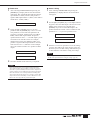
IMPORTANT SAFETY INSTRUCTIONS
1 Read these instructions.
2Keep these instructions.
3 Heed all warnings.
4 Follow all instructions.
5 Do not use this apparatus near water.
6 Clean only with dry cloth.
7 Do not block any ventilation openings. Install
in accordance with the manufacturer’s instruc-
tions.
8 Do not install near any heat sources such as
radiators, heat registers, stoves, or other appa-
ratus (including amplifiers) that produce heat.
9 Do not defeat the safety purpose of the polar-
ized or grounding-type plug. A polarized plug
has two blades with one wider than the other. A
grounding type plug has two blades and a third
grounding prong. The wide blade or the third
prong are provided for your safety. If the pro-
vided plug does not fit into your outlet, consult
an electrician for replacement of the obsolete
outlet.
10 Protect the power cord from being walked on
or pinched particularly at plugs, convenience
receptacles, and the point where they exit from
the apparatus.
11 Only use attachments/accessories specified by
the manufacturer.
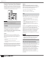
12 Use only with the cart,
stand, tripod, bracket, or
table specified by the manu-
facturer, or sold with the
apparatus. When a cart is
used, use caution when
moving the cart/apparatus
combination to avoid injury
from tip-over.
13 Unplug this apparatus during lightning storms
or when unused for long periods of time.
14 Refer all servicing to qualified service person-
nel. Servicing is required when the apparatus
has been damaged in any way, such as power-
supply cord or plug is damaged, liquid has
been spilled or objects have fallen into the
apparatus, the apparatus has been exposed to
rain or moisture, does not operate normally, or
has been dropped.
CAUTION: TO REDUCE THE RISK OF
ELECTRIC SHOCK, DO NOT REMOVE
COVER (OR BACK). NO USER-SERVICEABLE
PARTS INSIDE. REFER SERVICING TO
QUALIFIED SERVICE PERSONNEL.
CAUTION
RISK OF ELECTRIC SHOCK
DO NOT OPEN
WARNING
TO REDUCE THE RISK OF FIRE OR ELECTRIC SHOCK,
DO NOT EXPOSE THIS APPARATUS TO RAIN OR MOISTURE.

PRECAUTIONS
PLEASE READ CAREFULLY BEFORE PROCEEDING
* Please keep this manual in a safe place for future reference.
WARNING
Always follow the basic precautions listed below to avoid the possibility of serious injury or even death from
electrical shock, short-circuiting, damages, fire or other hazards. These precautions include, but are not limited
to, the following:
• Only use the voltage specified as correct for the device. The required
voltage is printed on the name plate of the PW5000.
• Use only the specified power supply PW5000.
• Do not place the power cord near heat sources such as heaters or radiators,
and do not excessively bend or otherwise damage the cord, place heavy
objects on it, or place it in a position where anyone could walk on, trip over,
or roll anything over it.
• Do not open the device or attempt to disassemble the internal parts or
modify them in any way. The device contains no user-serviceable parts. If it
should appear to be malfunctioning, discontinue use immediately and have
it inspected by qualified Yamaha service personnel.
• Do not expose the device to rain, use it near water or in damp or wet
conditions, or place containers on it containing liquids which might spill
into any openings.
• Never insert or remove an electric plug with wet hands.
• If the power cord or plug becomes frayed or damaged, or if there is a
sudden loss of sound during use of the device, or if any unusual smells or
smoke should appear to be caused by it, immediately turn off the power
switch, disconnect the electric plug from the outlet, and have the device
inspected by qualified Yamaha service personnel.
• If this device or the power supply should be dropped or damaged,
immediately turn off the power switch, disconnect the electric plug from the
outlet, and have the device inspected by qualified Yamaha service
personnel.
CAUTION
Always follow the basic precautions listed below to avoid the possibility of physical injury to you or others, or
damage to the device or other property. These precautions include, but are not limited to, the following:
• Remove the electric plug from the outlet when the device is not to be used
for extended periods of time, or during electrical storms.
• When removing the electric plug from the device or an outlet, always hold
the plug itself and not the cord. Pulling by the cord can damage it.
•Turn the unit ON or OFF using only the POWER switch on the power supply
PW5000. Turning the unit ON or OFF by plugging or unplugging the power
cord, using a switch on a power tap, a breaker switch, or similar external
means can result in damage.
• Do not turn the PW5000 POWER switch OFF and ON in rapid succession.
Doing so can result in excessive current flow that can cause damage. Wait
at least 5 seconds before turning the POWER switch ON after it has been
turned OFF.
• When transporting or moving the device, always use six or more people.
• Before moving the device, remove all connected cables.
• Always remove the memory card before moving the console. Accidental
impact or shock during transport can damage the memory card and/or the
card reader unit.
•Avoid setting all equalizer controls and faders to their maximum.
Depending on the condition of the connected devices, doing so may cause
feedback and may damage the speakers.
• Do not expose the device to excessive dust or vibrations, or extreme cold
or heat (such as in direct sunlight, near a heater, or in a car during the day)
to prevent the possibility of panel disfiguration or damage to the internal
components.
• Do not place the device in an unstable position where it might accidentally
fall over.
• Do not block the vents. This device has ventilation holes at the top/front/
rear to prevent the internal temperature from rising too high. In particular,
do not place the device on its side or upside down, or place it in any
poorly-ventilated location, such as a bookcase or closet.
• Do not use the device in the vicinity of a TV, radio, stereo equipment,
mobile phone, or other electric devices. Otherwise, the device, TV, or radio
may generate noise.
Power supply/Power cord
Do not open
Water warning
If you notice any abnormality
Power supply/Power cord Location
(5)-1 1/3

• Before connecting the device to other devices, turn off the power for all
devices. Before turning the power on or off for all devices, set all volume
levels to minimum.
• Do not insert your fingers or hand in any gaps or openings on the device
(vents, etc.).
•Avoid inserting or dropping foreign objects (paper, plastic, metal, etc.) into
any gaps or openings on the device (vents, etc.) If this happens, turn off
the power immediately and unplug the power cord from the AC outlet. Then
have the device inspected by qualified Yamaha service personnel.
• Do not use the device or headphones for a long period of time at a high or
uncomfortable volume level, since this can cause permanent hearing loss.
If you experience any hearing loss or ringing in the ears, consult a
physician.
• Do not rest your weight on the device or place heavy objects on it, and
avoid use excessive force on the buttons, switches or connectors.
• This device has a built-in backup battery. When you unplug the power cord
from the AC outlet, the internal data is retained. However, if the backup
battery fully discharges, this data will be lost. When the backup battery is
running low, the display indicates “LoBT(Low Battery).” In this case,
immediately save the data to a Memory Card (CompactFlash), then have
qualified Yamaha service personnel replace the backup battery.
XLR-type connectors are wired as follows (IEC60268 standard): pin 1: ground, pin 2: hot (+), and pin 3: cold (-).
Yamaha cannot be held responsible for damage caused by improper use or modifications to the device, or data that is lost or destroyed.
Always turn the power off when the device is not in use.
The performance of components with moving contacts, such as switches, volume controls, connectors, and fans, deteriorates over time. Consult qualified Yamaha
service personnel about replacing defective components.
Connections
Handling caution
Backup battery
(5)-1 2/3

* This applies only to products distributed by YAMAHA CORPORATION OF AMERICA. (class B)
ADVARSEL!
Lithiumbatteri—Eksplosionsfare ved fejlagtig håndtering.
Udskiftning må kun ske med batteri af samme fabrikat og
type. Levér det brugte batteri tilbage til leverandoren.
VARNING
Explosionsfara vid felaktigt batteribyte. Använd samma batter-
ityp eller en ekvivalent typ som rekommenderas av apparat-
tillverkaren. Kassera använt batteri enligt fabrikantens
instruktion.
VAROITUS
Paristo voi räjähtää, jos se on virheellisesti asennettu. Vaihda
paristo ainoastaan laitevalmistajan suosittelemaan tyyppiin.
Hävitä käytetty paristo valmistajan ohjeiden mukaisesti.
(lithium caution)
NEDERLAND / THE NETHERLANDS
• Dit apparaat bevat een lithium batterij voor geheugen back-up.
• This apparatus contains a lithium battery for memory back-up.
• Raadpleeg uw leverancier over de verwijdering van de batterij
op het moment dat u het apparaat ann het einde van de lev-
ensduur afdankt of de volgende Yamaha Service Afdeiing:
Yamaha Music Nederland Service Afdeiing
Kanaalweg 18-G, 3526 KL UTRECHT
Tel. 030-2828425
•For the removal of the battery at the moment of the disposal
at the end of the service life please consult your retailer or
Yamaha Service Center as follows:
Yamaha Music Nederland Service Center
Address : Kanaalweg 18-G, 3526 KL UTRECHT
Tel: 030-2828425
• Gooi de batterij niet weg, maar lever hem in als KCA.
• Do not throw away the battery. Instead, hand it in as small
chemical waste.
(lithium disposal)
FCC INFORMATION (U.S.A.)
1. IMPORTANT NOTICE: DO NOT MODIFY THIS
UNIT!
This product, when installed as indicated in the instruc-
tions contained in this manual, meets FCC requirements.
Modifications not expressly approved by Yamaha may void
your authority, granted by the FCC, to use the product.
2. IMPORTANT: When connecting this product to accesso-
ries and/or another product use only high quality shielded
cables. Cable/s supplied with this product MUST be used.
Follow all installation instructions. Failure to follow instruc-
tions could void your FCC authorization to use this product
in the USA.
3. NOTE: This product has been tested and found to comply
with the requirements listed in FCC Regulations, Part 15
for Class “B” digital devices. Compliance with these
requirements provides a reasonable level of assurance
that your use of this product in a residential environment
will not result in harmful interference with other electronic
devices. This equipment generates/uses radio frequencies
and, if not installed and used according to the instructions
found in the users manual, may cause interference harmful
to the operation of other electronic devices. Compliance
with FCC regulations does not guarantee that interference
will not occur in all installations. If this product is found to
be the source of interference, which can be determined by
turning the unit “OFF” and “ON”, please try to eliminate the
problem by using one of the following measures:
Relocate either this product or the device that is being
affected by the interference.
Utilize power outlets that are on different branch (circuit
breaker or fuse) circuits or install AC line filter/s.
In the case of radio or TV interference, relocate/reorient
the antenna. If the antenna lead-in is 300 ohm ribbon lead,
change the lead-in to co-axial type cable.
If these corrective measures do not produce satisfactory
results, please contact the local retailer authorized to dis-
tribute this type of product. If you can not locate the appro-
priate retailer, please contact Yamaha Corporation of
America, Electronic Service Division, 6600 Orangethorpe
Ave, Buena Park, CA90620
The above statements apply ONLY to those products dis-
tributed by Yamaha Corporation of America or its subsid-
iaries.
(5)-1 3/3

Foreword
6
Foreword
Thank you for choosing a Yamaha PM5000 Mixing Console. The PM5000 is the
proud successor to the highly acclaimed Yamaha PM4000, which became the
definitive sound reinforcement console of the preceding decade in terms of both
performance and features.
The PM5000 carries on the PM-series pedigree with unprecedented sound and
operability, while inheriting new digital control features from Yamaha’s top-line
PM1D digital console. In an era in which digital consoles are becoming the
mainstream, the PM5000 represents the peak of refinement in analog sound
technology, with the added benefits of digital control.
Please read this manual carefully before use to ensure that you benefit from the
maximum performance and control capabilities that your PM5000 can deliver.
Also keep the manual safe but handy so you can refer to later.
Copying of the commercially available music data and/or digital audio files is strictly prohibited except for
your personal use.
* The illustrations and screen displays as shown in this Owner’s Manual are for instructional purposes
only, and may be different from the ones on your device.
* The company names and product names in this Owner’s Manual are the trademarks or registered
trademarks of their respective companies.
* CompactFlash is a registered trademark of SanDisk Corporation.

About This Manual
7
About This Manual
General Approach
Most of this manual is devoted to describing the features and functions of the various PM5000 modules.
Since the operational design of the PM5000 is based on familiar analog console principles, anyone who is
familiar with the PM4000 or similar consoles should be able to begin operating the PM5000 without
hesitation. New features and multi-module control operations will be described in column form.
The names of physical controls such as buttons and knobs will be shown in square brackets.
The manual is organized as follows:
■ PM5000 Overview (page 10)
The names and functions of the various sections of the console are broadly described in the context of
the console as a whole. Please read this section before continuing on to the details. This section
explains the console’s overall internal signal flow and how it relates to external equipment.
■ The Sections and Modules (page 15)
Following the signal flow from input to output, the individual features and functions of each section
and module are described individually.
■ Scene Memory Functions (page 51)
Operation of the PM5000 scene memory functions, including storage of panel settings and motor fader
operations, is described here.
■ Utility Functions (page 56)
This section describes operation of the utility functions relating to overall system setup and
communication with external equipment.
■ Appendix (page 84)
Options, plugs and connectors, and other information for general operation and maintenance.
References, hints, and additional information will be provided throughout the text where appropriate.
The PM5000 Models
The PM5000 series includes three basic models, as described below:
■ PM5000-52C (52 input channels/center master)
■ PM5000-36 (36 input channels/right master)
■ PM5000-28 (28 input channels/right master)
For each model the number following “PM5000” refers to the total number of mono and stereo input
channels. The only actual difference between models is the number of mono input modules. All other
modules and configuration are the same. This manual applies to all three models.

8
Contents
Foreword 6
About This Manual 7
General Approach ....................................... 7
The PM5000 Models .................................... 7
PM5000 Overview 10
Panel Layout .............................................. 10
Top Panel ................................................... 10
Rear Panel .................................................. 12
Expansion: Connecting to
External Equipment .............. 14
Cascade ........................................................ 14
MIDI................................................................ 14
GPI (General Purpose Interface)................. 14
Input Channel Section 15
Mono and Stereo Input Modules .............. 15
Head Amp Block........................................... 15
HPF Block ..................................................... 16
EQ Block ....................................................... 16
Insert Block................................................... 17
Stereo Aux Send 1~12 Block ...................... 17
G/A (Group/Aux) Send 1~8 Block ............... 18
Main Out Block ............................................. 18
Channel Fader Block ................................... 20
Channel Grouping ..................................... 21
VCA Grouping .............................................. 21
Assigning VCA and Mute Groups............... 21
VCA Master and
Master Mute Switch Group Control ............ 24
Master Out Section 26
Multiple Masters In
Single Modules .......................................... 26
Basic Signal Routing................................. 27
Controls Common To All Masters............ 28
Stereo Aux Master Module ....................... 30
G/A (Group/Aux) Master Module .............. 31
Group/Aux Switching................................... 32
Stereo and Mono Master Modules ........... 34
Matrix Send and
Master Out Section 35
Matrix Send Section .................................. 35
Matrix Master Out Section ........................ 37
Oscillator and
Talkback Section 38
Oscillator/Talkback Signal Output ........... 39

9
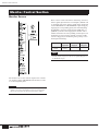
Monitor Control Section 40
Monitor Source........................................... 40
The Monitor Outputs.................................. 41
Cue Signal Monitoring............................... 41
Solo Mode................................................... 44
Cue and Solo .................................................44
Basic Operation ............................................45
Meter Bridge ............................................... 47
Digital Control Section 49
Control Functions ...................................... 49
Scene Memory Functions ......................... 51
Overview ........................................................51
Fade Time ......................................................52
Scene Store ...................................................53
Scene Recall..................................................53
Title Edit........................................................54
The Preview Function...................................55
Utility Functions......................................... 56
Overview ........................................................56
Common Operations ....................................57
Basic Functions ............................................58
Battery Check ............................................58
Date/Time ..................................................59
CompactFlash Memory..............................59
Lock Mode .................................................61
Memory Protect .........................................62
Scene Edit .................................................62
Bus Mode.......................................................63
G/A Bus Mode ...........................................63
Stereo Matrix Mode ...................................64
Safety and Protection Functions.................65
Group Assign Safe.....................................65
G/A Bus Assign Safe .................................65
Recall Safe Select .....................................66
Solo Enable ...............................................66
Input Solo Safe ..........................................67
Monitor .......................................................... 67
Monitor Mode ............................................ 67
Monitor Delay............................................ 68
Master Cue AFL Position .......................... 69
Scene Recall ................................................. 69
Theater Mode............................................ 69
Fader Mode............................................... 70
Automation................................................ 70
Direct Recall/ Mute Master........................ 71
GPI ................................................................. 72
Scene Inc/Dec (GPI In) ............................. 72
GPI Out ..................................................... 72
Cascade ........................................................ 74
Cascade.................................................... 76
MIDI................................................................ 77
MIDI Program Change .............................. 80
MIDI Control Change ................................ 81
MIDI Setting .............................................. 81
MIDI Echo Back ........................................ 82
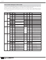
MIDI Program Change Table .................... 83
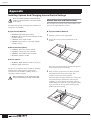
Appendix 84
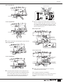
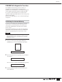
Installing Options And
Changing Internal Switch Settings ...........84
Module Removal and Replacement............ 84
Input Transformer Installation .................... 86
Internal Switch Settings For
Each module................................................. 88
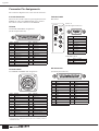
Connector Pin Assignments .....................92
PM5000 Self-diagnostic Function .............93
Initializing the Internal Memory .................. 93
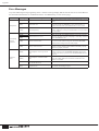
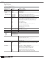
Error Messages...........................................94
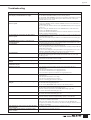
Troubleshooting .........................................95
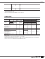
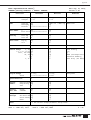
Specifications .............................................96
1. General Specifications ............................ 96
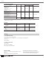
2. Inputs/Outputs.......................................... 97
3. Others........................................................ 98
MIDI Data Format ........................................99
Index 102

PM5000 Overview
10
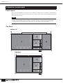
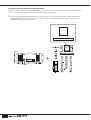
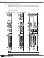
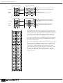
Panel Layout
The layout of the PM5000’s functional sections in the basic configuration is shown below. In the PM5000-
52C the master output section is located in the center of the console, while in all other models it is located
to the right of the console.
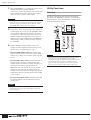
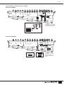
Top Panel
PM5000 Overview
NOTE
In this manual the console’s main functional groups are referred to as “sections.” Each section further contains “blocks” of
functions. The basic hardware divisions are “modules.” For example, all of the console’s input modules make up the “input
channel section.” Each input channel is made up of an “EQ block,” a “fader block,” and others. In the PM5000 each input
channel is made up of two separate hardware components: an “input channel module” and a “fader module.”
PM5000-28
PM5000-52C

11
PM5000 Overview
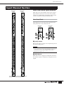
1 Input Channel Section (page 15)
Two types of input channels are provided – mono and
stereo – but the basic block structure of each is the same.
After going through phantom power, input gain, phase
reversal, and high-pass filter stages, the audio signal
passes through a 4-band equalizer before it reaches the
channel fader. External processing gear can be inserted
into the channel signal path either before or after the EQ
block. The post-EQ signal can be sent to any or all of 12
stereo aux buses and 8 G/A (group/aux) buses. The audio
signal from the input channel can be assigned to the
stereo L&R bus and/or mono bus. On mono input
channels the signal can also be assigned to the stereo and
mono (center) buses in LCR mode. Up to 12 VCA
groups and 8 mute groups can be set for each channel’s
fader block. Furthermore, the channel on/off status,
master bus assign settings, grouping, and fader settings
can be stored in the console’s scene memory for instant
recall whenever required.
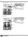
2 Master Output Section (page 26)
The master output section is further subdivided into
stereo aux master, G/A (group/aux) master, and stereo/
mono master sections. Each stereo aux master module
independently controls the signals from two adjacent
stereo aux buses (a total of 12 stereo aux buses).
Depending on the selected G/A bus mode, each G/A
master module can handle the signals from two adjacent
group/aux buses as up to 4 stereo pairs or 8 mono feeds.
The stereo and mono masters are integrated into a single
module, but are independent internally. The stereo and
mono masters receive the signals from the stereo and
mono buses, respectively, and send these signals to the
stereo and mono main outputs. Each master features a
SUB IN input and a [SUM GAIN] control for gain
adjustment. The on/off status of each master, as well as
bus assign and other settings can be stored in the
console’s scene memory.
3
Matrix Send and Master Out Section (page 35)
The matrix section is made up of 4 stereo and 8 mono
matrix mixes. The sends to the matrix mixes are all
derived from the master output section. The matrix input
section is located at the top of the master output section.
The signal from each master can be sent to a matrix bus
by turning the master’s [TO MATRIX] switch on and
using the matrix level controls to apply the signal to the
required matrix bus. The [SUB IN] control located next
to the stereo/mono master [SEND LEVEL] control
adjusts the level of the [MATRIX SUB IN L&R] signal
sent to each matrix bus.
The matrix output section is located to the right of the
matrix input section, and it is here that the final matrix
bus output levels are set. The stereo matrix buses can be
switched to function as mono sends via a utility mode
function, in which case the summed L & R mono signal
is delivered via the L and R outputs. The on/off status of
the matrix outputs can be stored in the console’s scene
memory.
4 VCA Master Section (page 21)
The VCA section can be used to independently control
up to 12 VCA groups (VCA1 ~ VCA12) set up via the
fader blocks of each input channel. The VCA master
faders function as master faders for the corresponding
VCA groups, while the [VCA MUTE] switches mute or
un-mute the corresponding VCA groups. With this
versatile system it is possible to assign a channel to
multiple VCA groups set up for different purposes.
5 Oscillator/Talkback Section (page 38)
From this section the oscillator and talkback signals can
be sent to any of the console’s master and matrix sends.
The [TB/OSC] switches in the master and matrix
sections assign the oscillator and talkback signals to the
corresponding output.
6 Monitor Control Section (page 40)
With two monitor outputs (MONITOR A & B) and
[CUE] switches on each module, any source or
combination of sources can be monitored as required.
Normally the same monitor signal is delivered via the
two main monitor outputs as well as the console’s three
headphone jacks (one at the top of the monitor module,
and two on either side of the front panel). When the
[LCR] switch is engaged the MONITOR A and B
outputs can be used simultaneously for LCR monitoring.
The [SOLO MODE] switches on the meter bridge allow
the module [CUE] switches to be used as solo switches
independently for the console’s input and output sections
(CUE/SOLO function).

12
PM5000 Overview
7 Mute Master Section (page 21)
The 8 [MUTE MASTER] switches can be used to mute
specified input channel groups, or as [DIRECT
RECALL] switches for the scene memory. Whether
these switches function in the MUTE MASTER or
DIRECT RECALL mode is specified via a utility mode
function.
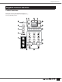
8 Digital Control Section (page 49)
The PM5000’s digital control features are concentrated
in this section. One of the main functions of this section
is storage and recall of console settings to and from the
scene memory. In addition to memorizing the on/off
status of panel switches, the scene memory can also
store fader settings that will be reproduced by the
motorized channel and VCA faders when recalled. A
fader time function is provided to specify the amount of
time it will take for the faders to physically reach the
recalled settings. This section also provides access to
utility functions that define basic operation of the
console and the way it interacts with some types of
external equipment. External CF (CompactFlash)
memory cards can be initialized and used to store scene
memory data.
9 Meter Bridge (page 47)
Used in conjunction with the monitor control section, the
meter bridge’s LED bar-graph meters provide visual
monitoring of final output levels at the console’s rear-
panel outputs. Indicators are also provided to display the
status of the PW5000 Power Supply unit as well as the
console’s internal fan unit and phantom power supplies.
Brightness controls for the console’s illuminated
controls and gooseneck lamps are also provided. Other
controls provided on the meter bridge are scene memory
preview on/off and mode selectors for the CUE/SOLO
function.
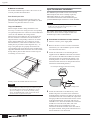
) Memory Card Slot
The console's memory card reader is located on the front
panel. The PM5000 can use CF (CompactFlash)
memory cards (see page 59).
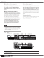
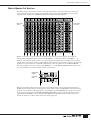
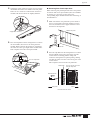
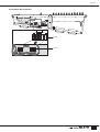
Rear Panel
NOTE
The two screws on the right side of the digital control section can
be used to attach a protective cover. The six screws on the sides of
the master sections can be used to attach a book rest or a talkback
cable. These 8 screws do not affect the mechanical strength of the
unit. Use the attached screws or M3-size machine screws 8
millimeters or less in length.
NOTE
All PM5000 inputs and outputs are balanced except for the PHONES outputs and expansion connectors. See the input/output specifications at the
end of this manual for details.
@##
&*( ™£¢
º¡º¡
$%^∞
@
!
PM5000-28
@##
&*( ™£¢
º¡º¡
$%^! !∞
@
PM5000-52C

13
PM5000 Overview
! Mono (Stereo) Inputs
XLR-type input connectors, DIRECT OUT connectors,
and INSERT IN and OUT connectors are provided on
each input channel. Stereo modules feature separate
connectors for the L and R channels, but do not have
DIRECT OUT connectors.
@ Sub Inputs
Each stereo aux master has L and R stereo aux SUB IN
connectors, each group/aux master has G/A SUB IN
connectors, both monitor outputs feature stereo 2TR IN
(1 & 2) and L/C/R CUE SUB IN connectors, and the
stereo and mono master outputs have L and R ST SUB
IN and MONO(C) SUB IN connectors. L and R
MATRIX SUB IN connectors are also provided for all
matrix outputs. Please check the supplied block diagram
for details.
# Insert Inputs and Outputs
Insert input and output connectors are provided on all 12
stereo aux masters, 8 group/aux masters, the stereo and
mono masters, and the 4 stereo matrix and 8 mono
matrix outputs.
$ Stereo Aux Master Out
% G/A (Group/Aux) Master Out
^ Matrix Out
The stereo aux master, G/A (group/aux) master, and
matrix output connectors are grouped together here.
& Monitor Out
These are the console’s two stereo monitor outputs (A &
B). You can use outputs A and B as separate stereo
monitor outputs, or use A and B simultaneously for LCR
monitoring (MONITOR B = Center).
* Talkback/Oscillator Out
The talkback or oscillator signal appears at this output.
( Stereo Output and Mono Output
These are the stereo and mono master outputs (ST OUT,
MONO (C)).
º Lamp Connectors
The supplied gooseneck lamps can be connected here (4
connectors on the PM5000-52C, 3 on the PM5000-36
and PM5000-28). Lamp brightness can be adjusted via
the [LAMP DIMMER] control on the meter bridge.
Engage the [LAMP OFF] switch to turn the lamps off.
¡ Fan Vents
These are the air vents for the console’s internal cooling
fans (4 locations on the PM5000-52C, 3 on the PM5000-
36 and PM5000-28). Be sure that the vents aren’t
blocked when installing the console.
™ Fan Switch
Sets the speed of the console’s internal cooling fans to
match prevailing operating conditions. Normally the
[LOW] setting can be used. When the ambient
temperature is high, however, such as in some outdoor
applications when the console is exposed to direct
sunlight, the [HIGH] setting should be used. Also switch
to the [HIGH] setting if the top-panel temperature feels
higher than normal.
£ +48V Master Switch
This is the master switch for the 48-volt phantom power
supply to all input channels. When using phantom power
use the individual input channel [+48V] switches to turn
phantom power on or off as required.
¢ External Expansion Connectors
Type A and B CASCADE connectors, a D-sub 25-pin
GPI connector, and MIDI IN/OUT/THRU connectors for
connection to compatible external equipment.
∞ Power Supply Connector
The dedicated external PW5000 power supply unit must
be connected to this connector using the power supply
cable supplied with the PM5000 console.
NOTE
Stereo aux SUB IN and G/A SUB IN connectors are not provided
on the PM5000-28.

14
PM5000 Overview
Expansion:Connecting to External Equipment
The PM5000 is entirely self-contained and can be used
effectively on its own, but it does provide some versatile
expansion capabilities. In this section we’ll describe how
the PM5000 can be synchronized with external gear and
cascaded with other Yamaha mixing consoles.
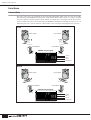
Cascade
Two types of cascade connectors are provided on the
PM5000 rear panel: TYPE [A] for connection to a
second PM5000, and TYPE [B] for connection to
Yamaha PM4000/3500 series mixing consoles. In either
case the extra console will be added to increase the total
number of available input channels.
Type A
When the TYPE [A] connectors of two PM5000 consoles are
connected via a cross cable the functions listed below become
linked between the master and slave consoles. The slave console’s
utility mode can be used to specify reception of individual
parameters.
• VCA master section (mute & fade, fade time link).
• Mute master.
• The cue/solo setting (sync of all cue groups).
• Scene memory (synchronized storage and recall of the same
scene number).
The TYPE [A] port can also be connected to the serial RS-422 or
RS-232C port of a personal computer for offline console parameter
editing. PM5000 setup data can be transferred to and from the
console in standard CSV file format and edited in any spreadsheet
application that can import and export CSV data. The edited data
can then be directly read back into the PM5000.
Type B
The TYPE [B] cascade connector can be used to connect the
PM5000 to a Yamaha PM4000 or PM3500 series console for
linkage of the functions listed below. In this case the PM5000 will
function as the master console, there is no need to use the utility
mode to set the receive parameters. Cue/solo settings can,
however, be transmitted from the PM4000/3500.
• VCA master section (mute & fade, fade time link).
• Mute master (except for the PM3500).
• The cue/solo setting (sync of input cue only).
MIDI
The PM5000 MIDI connectors allow connection to other
MIDI equipment to provide the following capabilities:
• Program change message reception from an external MIDI
device for scene memory selection.
• Transmission of appropriate program change messages to
external MIDI gear when a scene memory is recalled on the
PM5000.
• Control change reception from an external MIDI device for
control of PM5000 panel control values.
• Transmission of appropriate control change messages to
external MIDI gear when a panel control is operated on the
PM5000.
In order to select the PM5000’s 1000 internal scene
memories using MIDI program change messages 1~128
it is necessary to use program change bank select
messages or create an program change table for the
PM5000. The program change table will also determine
which program change number is transmitted by the
PM5000 when a scene memory is recalled. MIDI
settings can be accessed via the console’s utility
functions. Also refer to the MIDI data list at the end of
this manual.
GPI (General Purpose Interface)
The GPI port allows pulse-signal interfacing with
compatible external equipment for bi-directional control
of several functions. Receive functions include
incrementing or decrementing of the PM5000 scene
memory and talkback on/off switching. GPI data can be
transmitted when a fader is operated (manually or
automatically), or when a specified scene memory is
recalled. All of these functions are accessible via the
PM5000 utility functions. Refer to the GPI Pin
Assignments chart at the end of this manual for more
information.
NOTE
See the detailed descriptions of the related utility functions in the
Utility Functions section beginning on page 56.
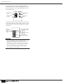
THRU
OUT
IN
MIDI
GPI
RS232C
RS422
MASTER
SLAVE
A
B
NOTE
Appropriate MIDI cables must be connected from the OUT
connector of the transmitting device to the IN connector of the
receiving device. The THRU connector on the receiving devices
re-transmits the data received at the IN connector. On the
PM5000 an “echo” function can be used to retransmit data
received at the IN connector via the OUT connector.

15
Input Channel Section
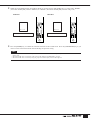
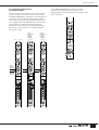
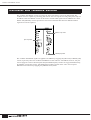
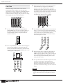
Mono and Stereo Input Modules
Mono and stereo input modules make up the console’s
input channel section. In essence each stereo module
contains two parallel mono signal paths, and the panel
controls control both channels simultaneously.
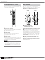
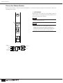
Head Amp Block
Initial adjustment of the input audio signal level and
other parameters can be carried out here.
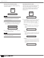
1 [+48V] Switch
Engage this switch to supply +40-volt phantom power to
the corresponding input.
2 [PAD] Switch
When this switch is engaged a 26-db pad is inserted at
the channel’s input to compensate for high-level source
signals.
Input Channel Section
Mono Input
Module
Stereo Input
Module
The arrows indicate controls and indicators that differ
between the mono and stereo input modules.
NOTE
In order to use phantom power, the rear-panel [+48V MASTER]
switch must be turned on. The [+48V MASTER ON] indicator on
the left side of the meter bridge will light when the master
phantom power switch is on.
Mono Input
Module
Stereo Input
Module
1 14
55
3 3
2 2

16
Input Channel Section
3 [GAIN] Control
Adjusts the input level. When the [PAD] switch is off the
input level can be adjusted from –10 dB through –60 dB.
When the [PAD] switch is engaged the range is from +16
dB through –34 dB.
4 [L+R] Switch (stereo modules only)
When this switch is engaged the stereo input signal is
summed to a mono mix, allowing the stereo input
modules to be used as mono input modules, as required.
5 [ø] (Phase) Switch
Engaging this switch reverses the phase (also referred to
as the “polarity”) of the input signal.
HPF Block
The high-pass filter can be used to attenuate unwanted
low-frequency noise that can adversely affect the overall
sound.
6 [HPF] Switch and Control
The filter is activated when the switch engaged, and the
control can be used to adjust the high-pass filter cutoff
frequency from 20 Hz through 400 Hz. The filter has a
12-dB/oct. cutoff slope.
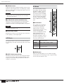
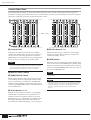
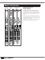
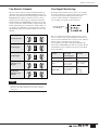
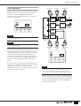
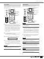
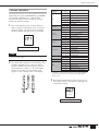
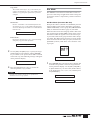
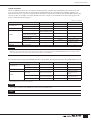
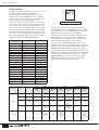
EQ Block
This 4-band equalizer features
individually-adjustable HIGH,
HI-MID, LO-MID, and LOW
bands for versatile shaping of
the channel signal. The HIGH
and LOW bands are switchable
between shelving and peaking
operation, while the HI-MID
and LO-MID bands are peaking
types.
7 EQ Controls
Two controls are provided for
each EQ band: the upper “Q”
control adjusts bandwidth,
while the lower concentric
control adjusts frequency (outer
control) and gain (inner
control). The HIGH and LOW
bands additionally have a
peaking/shelving switch that
determines the band’s mode of
operation: engaging the switch
selects the shelving mode.
* For all bands Q (bandwidth) can be adjusted from 0.5 ~ 3.0.
8 [EQ] Switch
Turns the 4-band EQ block on or off. When the [EQ]
switch indicator is off the EQ circuitry is bypassed. EQ
is active when the indicator is lit.
NOTE
Stereo modules feature concentric gain controls: the inner control
adjusts the gain of the left channel and the outer control adjusts
the gain of the right channel.
NOTE
To maintain the proper subjective signal level the left and right
channels are attenuated by 3 dB.
6
HIGH
1 kHz ~ 20 kHz, -15 dB ~ +15 dB (peaking
and shelving modes)
HI-MID 400 Hz ~ 8 kHz, -15 dB ~ +15 dB
LO-MID 80 Hz ~ 1.6 kHz, -15 dB ~ +15 dB
LOW
30 Hz ~ 600 Hz, -15 dB ~ +15 dB (peaking
and shelving modes)
7
8

17
Input Channel Section
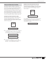
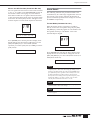
Insert Block
These switches are used to determine whether and where
external processing gear connected to the rear-panel
INSERT IN and OUT connectors will be inserted into
the channel signal path.
9 Insert [ON] Switch
Turns channel insert on or off. When the [ON] switch is
engaged an external equipment connected to the rear-
panel INSERT IN connectors is inserted into the
channel’s signal path. The [PRE] switch (below)
determines whether the insert is pre- or post-EQ.
) [PRE] Switch
Determines whether the channel’s INSERT IN and OUT
connectors insert the externally connected gear before or
after the channel EQ stage. When the switch is off the
insert is post-EQ. When on (when the indicator is lit) the
insert is pre-EQ.
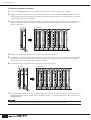
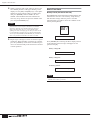
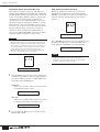
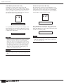
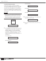
Stereo Aux Send 1~12 Block
The controls in this block determine
the levels at which the channel signal is
sent to the console’s 12 stereo aux
buses.
!
Send Level and Pan Controls
(mono modules)
Send Level and Balance
Controls (stereo modules)
The inner controls adjust send level (0
dB at approximately 2 o’clock), and
the outer controls adjust pan for mono
modules or balance for stereo modules.
@ [ON] Switch
When an [ON] switch is engaged the
send to the corresponding aux bus is
active.
# [PRE] Switch
When this switch is engaged the pre-
fader signal is sent to the
corresponding aux bus. When off, the
post-fader signal is sent to the aux bus.
NOTE
The channel signal appears at the rear-panel INSERT OUT
connector whether the INSERT [ON] switch is engaged or not.
9
)
!
@
#

18
Input Channel Section
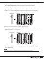
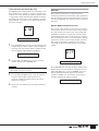
G/A (Group/Aux) Send 1~8 Block
These controls determine how the channel signal is sent
to the console’s 8 group/aux buses.
$ Send Level Controls
Adjust send level to the corresponding group/aux bus (0
dB at approximately 2 o’clock).
% [ON] Switch
When an [ON] switch is engaged the send to the
corresponding group/aux bus is active.
^ [PRE] Switch
When this switch is engaged the pre-fader signal is sent
to the corresponding group/aux bus. When off, the post-
fader signal is sent to the group/aux bus.
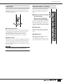
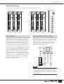
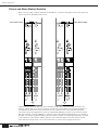
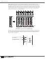
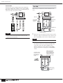
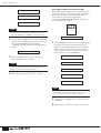
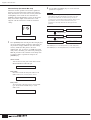
Main Out Block
This block determines how the channel signal is
assigned to the console’s main stereo and mono (center)
buses. The stereo and mono outputs can be used
independently, or combined for LCR output.
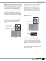
& [PAN]/[CSR] Control
(mono modules only)
Adjusts panning of the signal sent to the bus(es) to which
the channel signal is assigned via the main out switches
(. When the [ST] switch is engaged, assigning the
channel signal to the stereo bus, stereo panning is
adjusted via the inner control. When the [LCR] switch is
engaged and the channel signal is assigned to both the
stereo and mono buses in LCR mode, the outer [CSR]
(Center-Side Ratio) control can be used – refer to the
column below.
* [BAL] Control (stereo modules only)
Determines the stereo balance when the stereo-module
[ST] main out switch is engaged to send the channel
signal to the stereo bus.
NOTE
The above descriptions apply when the group/aux buses are used
as 8 mono aux buses (the default mode). The functions of the
controls will vary depending on the G/A bus mode selected via
the group/aux master section – refer to “Group/Aux Switching”
on page 32 for details.
$
%
^
&
(
*
º
º
Mono Input
Module
Stereo Input
Module
(
¡¡

19
Input Channel Section
( Main Out Switches
Determine where the post-fader channel signal will be
sent. To assign the channel signal to the stereo bus
engage the [ST] switch and use the [PAN] & or [BAL]
* control to adjust the stereo image. To send the signal
to the mono bus engage the [MONO] switch. In all cases
the channel fader determines the signal level.
On mono modules it is also possible to send the channel
signal to the stereo and mono buses in LCR mode, using
the mono bus as the center signal. To do this engage the
[LCR] switch and use the [CSR] control & to adjusts the
Center-Side Ratio to achieve the desired LCR balance.
º Channel [ON] Switch
Turns the input channel on or off. When off the channel
signal is not sent to the STEREO AUX, GROUP AUX,
STEREO or MONO buses.
¡ Level Meter
Displays the channels post-EQ pre-fader signal level.
The [PEAK] indicator will light when the signal level
exceeds 17 dB above nominal (0 dB) level.
NOTE
The [PEAK] indicator responds to the pre-EQ and pre-insert
signal level as well as to the post-EQ pre-fader level.
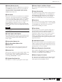
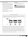
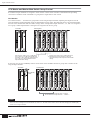
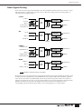
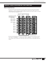
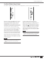
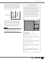
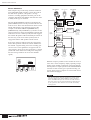
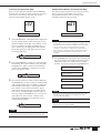
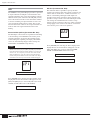
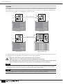
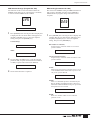
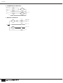
LCR vs. Stereo + Mono Operation
When the [LCR] switch is engaged the stereo and mono (center) buses become linked for LCR operation and the
[ST] and [MONO] switches cannot be engaged. On the other hand, when the [LCR] switch is not engaged the [ST]
and [MONO] switches can be engaged simultaneously. In either case the channel signal is sent to both the stereo and
mono buses. The difference between these two setups is described below.
For example, mono sources are normally positioned in the stereo sound field or swept from one side to the other by
adjusting the panning to the stereo bus. This works fine when the distance between the left and right speakers is
relatively small, but problems arise in venues where the speakers are further apart. In fact, in even modest venues if
a channel is panned fully left, for example, audience members sitting on the right side of the house will hear very
little of that signal, if any. In such cases it is useful to provide a center channel, the output level of which will be
adjusted to reinforce the stereo image and provide more effective coverage. Manually adjusting the levels and
panning of the stereo and mono buses to achieve this effect can be extremely difficult, and that’s where the LCR
output mode with CSR (Center-Side Ratio) control comes in handy. With this system and an LCR speaker setup it is
possible to produce natural stereo positioning and smooth panning in large venues with a single control. The [PAN]
control adjusts panning as always, while the [CSR] control determines how the center channel responds to [PAN]
control operation as shown in the diagrams above. The more the [CSR] control is rotated clockwise, the higher the
center channel level as the [PAN] control approaches center position.
Outer: CSR
Inner: PAN
L Bus Level
R Bus Level
MONO(C) Bus Level
CSR Control: LR CSR Control: Center CSR Control: CSR
LR CSR LR CSR LR CSR

20
Input Channel Section
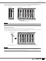
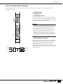
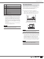
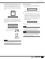
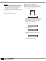
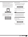
Channel Fader Block
The channel faders determine the level of the channel signal sent to the console’s master buses, and are of primary
importance in setting up the balance between the various channels in the mix. The channel faders can also be assigned to
specific VCA and mute groups for group level and mute control.
™ Channel Fader
Adjusts the out signal level from the corresponding
channel. The channel faders also affect the signal level
sent to the stereo aux and group/aux buses when the
[PRE] switches associated with the corresponding sends
are off (i.e. they are sending the post-fader signal).
£ [RECALL SAFE] Switch
¢ [FADER SAFE] Switch
Either of these switches can be engaged to prevent the
corresponding data from changing the channel settings
when a scene memory is recalled. Use the [RECALL
SAFE] switch to maintain the master bus assign switch
settings, or [FADER SAFE] switch to maintain the level
of the channel fader.
∞ VCA Indicators 1~12
Indicate the VCA groups to which the corresponding
channel fader is assigned. If a VCA group master to
which the channel is assigned is muted via its [VCA
MUTE] switch, the corresponding VCA indicator will
flash rather than light continuously. More details are
provided in the “Channel Grouping” section on page 21.
§ MUTE Indicators 1~8
Indicate the mute groups to which the corresponding
channel is assigned. More details are provided in the
“Channel Grouping” section.
¶ [CUE] Switch
When this switch is engaged the pre-fader channel signal
is sent to the console’s CUE L&R buses regardless of the
channel’s on/off status. The cue signal can be monitored
via the rear-panel MONITOR OUT connectors or any of
the console’s PHONES jacks.
£
¢
™
¶
∞
§
NOTE
The channel faders are motor-drive types that will physically
move to the memorized settings when a scene memory is recalled
– after the specified “fade time,” if one has been programmed.
Refer to “Scene Memory Functions” on page 51 for details.
NOTE
Using the VCA CUE function, the post-fader channel signal can
be monitored.
NOTE
The [CUE] switches are also used to assign channels to VCA and
mute groups (page 21), as well as to specify target channels when
setting fade time parameters (page 52). Normal [CUE] switch
function is suspended while any of these operations are in
progress.
Sidan laddas ...
Sidan laddas ...
Sidan laddas ...
Sidan laddas ...
Sidan laddas ...
Sidan laddas ...
Sidan laddas ...
Sidan laddas ...
Sidan laddas ...
Sidan laddas ...
Sidan laddas ...
Sidan laddas ...
Sidan laddas ...
Sidan laddas ...
Sidan laddas ...
Sidan laddas ...
Sidan laddas ...
Sidan laddas ...
Sidan laddas ...
Sidan laddas ...
Sidan laddas ...
Sidan laddas ...
Sidan laddas ...
Sidan laddas ...
Sidan laddas ...
Sidan laddas ...
Sidan laddas ...
Sidan laddas ...
Sidan laddas ...
Sidan laddas ...
Sidan laddas ...
Sidan laddas ...
Sidan laddas ...
Sidan laddas ...
Sidan laddas ...
Sidan laddas ...
Sidan laddas ...
Sidan laddas ...
Sidan laddas ...
Sidan laddas ...
Sidan laddas ...
Sidan laddas ...
Sidan laddas ...
Sidan laddas ...
Sidan laddas ...
Sidan laddas ...
Sidan laddas ...
Sidan laddas ...
Sidan laddas ...
Sidan laddas ...
Sidan laddas ...
Sidan laddas ...
Sidan laddas ...
Sidan laddas ...
Sidan laddas ...
Sidan laddas ...
Sidan laddas ...
Sidan laddas ...
Sidan laddas ...
Sidan laddas ...
Sidan laddas ...
Sidan laddas ...
Sidan laddas ...
Sidan laddas ...
Sidan laddas ...
Sidan laddas ...
Sidan laddas ...
Sidan laddas ...
Sidan laddas ...
Sidan laddas ...
Sidan laddas ...
Sidan laddas ...
Sidan laddas ...
Sidan laddas ...
Sidan laddas ...
Sidan laddas ...
Sidan laddas ...
Sidan laddas ...
Sidan laddas ...
Sidan laddas ...
Sidan laddas ...
Sidan laddas ...
Sidan laddas ...
Sidan laddas ...
Sidan laddas ...
Sidan laddas ...
-
 1
1
-
 2
2
-
 3
3
-
 4
4
-
 5
5
-
 6
6
-
 7
7
-
 8
8
-
 9
9
-
 10
10
-
 11
11
-
 12
12
-
 13
13
-
 14
14
-
 15
15
-
 16
16
-
 17
17
-
 18
18
-
 19
19
-
 20
20
-
 21
21
-
 22
22
-
 23
23
-
 24
24
-
 25
25
-
 26
26
-
 27
27
-
 28
28
-
 29
29
-
 30
30
-
 31
31
-
 32
32
-
 33
33
-
 34
34
-
 35
35
-
 36
36
-
 37
37
-
 38
38
-
 39
39
-
 40
40
-
 41
41
-
 42
42
-
 43
43
-
 44
44
-
 45
45
-
 46
46
-
 47
47
-
 48
48
-
 49
49
-
 50
50
-
 51
51
-
 52
52
-
 53
53
-
 54
54
-
 55
55
-
 56
56
-
 57
57
-
 58
58
-
 59
59
-
 60
60
-
 61
61
-
 62
62
-
 63
63
-
 64
64
-
 65
65
-
 66
66
-
 67
67
-
 68
68
-
 69
69
-
 70
70
-
 71
71
-
 72
72
-
 73
73
-
 74
74
-
 75
75
-
 76
76
-
 77
77
-
 78
78
-
 79
79
-
 80
80
-
 81
81
-
 82
82
-
 83
83
-
 84
84
-
 85
85
-
 86
86
-
 87
87
-
 88
88
-
 89
89
-
 90
90
-
 91
91
-
 92
92
-
 93
93
-
 94
94
-
 95
95
-
 96
96
-
 97
97
-
 98
98
-
 99
99
-
 100
100
-
 101
101
-
 102
102
-
 103
103
-
 104
104
-
 105
105
-
 106
106


Yamaha PM5000 Bruksanvisning
- Kategori
- Kompletterande musikutrustning
- Typ
- Bruksanvisning
på andra språk
- italiano: Yamaha PM5000 Manuale del proprietario
- čeština: Yamaha PM5000 Návod k obsluze
- español: Yamaha PM5000 El manual del propietario
- Deutsch: Yamaha PM5000 Bedienungsanleitung
- polski: Yamaha PM5000 Instrukcja obsługi
- português: Yamaha PM5000 Manual do proprietário
- français: Yamaha PM5000 Le manuel du propriétaire
- 日本語: Yamaha PM5000 取扱説明書
- Türkçe: Yamaha PM5000 El kitabı
- English: Yamaha PM5000 Owner's manual
- dansk: Yamaha PM5000 Brugervejledning
- русский: Yamaha PM5000 Инструкция по применению
- suomi: Yamaha PM5000 Omistajan opas
- Nederlands: Yamaha PM5000 de handleiding
- română: Yamaha PM5000 Manualul proprietarului