
LV Capacitor Bank APC
Installation, operation and maintenance instructions
Batteries automatiques de condensateurs basse tension APC
Instructions d’installation, d’utilisation et d’entretien
Pienjännitekompensointiparistot APC
Asennus-, käyttö- ja huolto-ohjeet
Kondensatorbank för lågspänning, APC
Instruktioner för installation, drift och underhåll
ABB
en fr fi sv

APC - Content
2
Content
English Page 4
Français Page 32
Suomi Sivu 60
Svenska Sid 88
en
fr
fi
sv

APC - Content
3
While all care has been taken to ensure that the information contained in this publication is correct, no responsibility can be accepted for
any inaccuracy. The Company reserves the right to alter or modify the information contained herein at any time in the light of technical
or other developments. Technical specifications are valid under normal operating conditions only. The Company does not accept any
responsibility for any misuse of the product and cannot be held liable for indirect or consequential damages.
Bien que tout soit mis en oeuvre pour garantir l’exactitude des informations contenues dans cette publication, nous n’acceptons aucune
responsabilité légale pour toute information incorrecte. Nous déclinons toute responsabilité en cas de mauvaise utilisation du produit
ainsi que pour les éventuels dommages en résultant, qu’ils soient directs ou indirects. Nous nous réservons le droit de changer ou de
modifier à tout moment les informations contenues dans cette publication à la lumière des développements techniques ou autres. Les
spécifications techniques sont valables uniquement sous conditions de fonctionnement normales.
Julkaisujen tietojen oikeellisuus on pyritty varmistamaan kaikin tavoin, mutta epätäsmällisyyksistä ei vastata. Pidätämme oikeuden
muuttaa tässä julkaistuja tietoja milloin hyvänsä ennalta ilmoittamatta tekniikan kehittyessä tai muista syistä. Tekniset tiedot ovat
voimassa vain normaaleissa käyttöoloissa. Emme vastaa tuotteen virheellisestä käytöstä, eikä meitä voida pitää vastuuvelvollisina
välillisistä tai seurannaisvahingoista.
Stor vikt har lagts vid att all information i denna publikation ska vara korrekt, men inget ansvar kan tas för eventuella fel. Företaget
förbehåller sig rätten att när som helst ändra informationen häri på grund av teknisk utveckling eller andra händelser. Tekniska
specifikationer gäller bara vid normala driftsförhållanden. Företaget tar inget ansvar då produkten missbrukas och kan inte hållas
skyldiga för indirekta skador eller följdskador.
en
fr fi sv

APC - Table of contents
4
en
Table of contents
1. Read this first ............................................................................................................7
1.1. About this instruction manual...........................................................................................................7
1.2. Safety ...............................................................................................................................................7
1.3. APC types ........................................................................................................................................7
1.4. Inspection on reception ....................................................................................................................7
1.5. Guarantee ........................................................................................................................................8
1.6. Storage.............................................................................................................................................8
1.7. Handling ...........................................................................................................................................8
1.8. Electric insulation test.......................................................................................................................8
2. APC description.........................................................................................................9
2.1. Power modules...............................................................................................................................10
2.2. Ventilation system ..........................................................................................................................10
2.2.1. Thermistor ................................................................................................................................................11
2.2.2. Temperature probe ...................................................................................................................................11
3. Installation ...............................................................................................................12
3.1. Location..........................................................................................................................................12
3.2. Harmonics ......................................................................................................................................12
3.3. Fixation...........................................................................................................................................12
3.3.1. APCL1 and APCL2 boxes ........................................................................................................................12
3.3.2. APCM1, APCM2 and APCR cubicles .......................................................................................................12
3.4. Connection .....................................................................................................................................12
3.4.1. Electrical diagram .....................................................................................................................................13
3.4.2. Connection of several banks in parallel (master units or master unit + slave unit configuration) ..............13
3.4.3. Power cables connection..........................................................................................................................14
3.4.3.1. APCL1 and APCL2 boxes...................................................................................................................14
3.4.3.2. APCM1, APCM2 and APCR cubicles..................................................................................................15
3.4.4. Current transformer connection ................................................................................................................15
3.4.5. Slave (AUX) to master (PIL) unit connection (for master unit + slave unit configuration) .........................17
3.4.5.1. Master (PIL) APCL2 wiring..................................................................................................................18
3.4.5.2. Master (PIL) APCM2 wiring.................................................................................................................18
3.4.5.3. Master (PIL) APCR wiring ...................................................................................................................19
3.4.6. Earth connection.......................................................................................................................................19
4. Easy commissioning...............................................................................................20
4.1. Front view.......................................................................................................................................23
4.2. Rear view .......................................................................................................................................24
5. Troubleshooting ......................................................................................................25
6. Maintenance.............................................................................................................26
6.1. APC maintenance ..........................................................................................................................26
6.2. APCR capacitors module replacement ..........................................................................................26
6.3. Access to reactors..........................................................................................................................28

APC - Table of contents
5
en
7. Appendices ..............................................................................................................29
7.1. Technical specifications .................................................................................................................29
7.2. Dimensions and weights ................................................................................................................30

APC - Table of figures
6
en
Table of figures
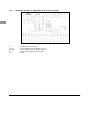
Figure 1.1. APCM and APCR setting upright..................................................................................................... 8
Figure 2.1. APC types........................................................................................................................................ 9
Figure 2.2. APCL2 of 125kvar/400V .................................................................................................................. 9
Figure 2.3. APCM2 of 400kvar/400V .................................................................................................................9
Figure 2.4. APCR of 300kvar/400V....................................................................................................................9
Figure 2.5. Example of a front face and rear face (APCM module).................................................................10
Figure 2.6. Example of a front face and rear face (APCR module) .................................................................10
Figure 2.7. Temperature probe ........................................................................................................................ 11
Figure 3.1. Air grids and cable entry in APCM and APCR............................................................................... 12
Figure 3.2. Electrical diagram .......................................................................................................................... 13
Figure 3.3. Connection of several banks in parallel......................................................................................... 14
Figure 3.4. Power cables connection to the incoming power terminals for boxes........................................... 15
Figure 3.5. Power cables connection to the incoming power terminals for cubicles .......................................15
Figure 3.6. CT connection and release contact ...............................................................................................16
Figure 3.7. Multi ratio CT..................................................................................................................................16
Figure 3.8. Summation CT............................................................................................................................... 16
Figure 3.9. Slave to master unit connection.....................................................................................................17
Figure 3.10. Interconnection cable location .....................................................................................................18
Figure 3.11. Master APCL2 wiring ...................................................................................................................18
Figure 3.12. Master APCM2 wiring ..................................................................................................................19
Figure 3.13. Master APCR wiring ....................................................................................................................19
Figure 3.14. Earth connection..........................................................................................................................19
Figure 4.1. View of the AUTO SET mode in RVC ...........................................................................................20
Figure 4.2. View of the target cos
ϕ
setting ..................................................................................................... 21
Figure 4.3. View of the programmable parameters .........................................................................................21
Figure 4.4. View of the “Feature” parameters.................................................................................................. 21
Figure 4.5. View of the Protections parameters...............................................................................................22
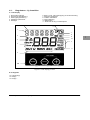
Figure 4.6. LCD display of the RVC................................................................................................................. 23
Figure 4.7. Rear view of the RVC ....................................................................................................................24
Figure 6.1. APCR 300kvar module 4 replacement .......................................................................................... 26
Figure 6.2. Disconnection of the contactor and the protection fuses............................................................... 27
Figure 6.3. Removal of the capacitor module .................................................................................................. 27
Figure 6.4. Access to reactors .........................................................................................................................28
Figure 7.1. APC dimensions and weights ........................................................................................................ 30

APC - Chapter 1. Read this first
7
en
1. Read this first
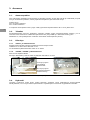
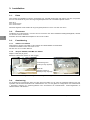
1.1. About this instruction manual
This instruction manual is intended to help you install and operate, quickly and efficiently, your APC
automatic capacitor bank, with the guarantee of optimum operation.
1.2. Safety
Before installation and operation of the APC automatic capacitor bank, read this instruction manual carefully.
Keep it at the disposal of the people in charge of the installation, operation and maintenance.
Do not introduce or store any extraneous body in the automatic capacitor bank.
Take care not to obstruct the ventilation grids.
Power capacitors operate continuously at full load. Please respect the points below:
Installation and maintenance must only be carried out by authorized and qualified personnel, in
accordance with current local regulations.
Isolate the equipment from the power supply before attempting to gain access.
Wait five minutes to allow the capacitor to discharge through the discharge resistors. As an additional
precaution before starting work, short-circuit the capacitor terminals with a piece of insulated cable (bare
at the ends) to confirm discharge.
Check that the secondary winding of the current transformer is short-circuited or connected to another
parallel load (with a sufficiently low impedance) while connecting or disconnecting measuring instruments
or relays. An open secondary winding of a loaded current transformer may cause dangerous
overvoltages.
The APC automatic capacitor bank must be installed according to EN 61921 and local specifications.
1.3. APC types
The APC exists in five different types:
2 types of boxes: APCL1 and APCL2
3 types of cubicles: APCM1, APCM2 and APCR
Note that APCL2, APCM2 and APCR types exist in slave execution. Slave units are not equipped with PF
controller but with an interconnection cable (factory wired).
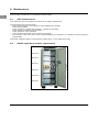
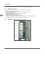
1.4. Inspection on reception
Make sure that the packaging has not been damaged in transit.
Any loss or damage should be notified immediately to your closest local ABB agent.
The small boxes (APCL1) are delivered upright.
The big boxes (APCL2) are delivered on their side and 2 units maximum can be stacked one on top of the
other for transit and storage.
The cubicles (APCM1 and APCM2) are also delivered on their side and 2 units maximum can be stacked
one on top of the other for transit and storage.
No stacking allowed for APCR.

APC - Chapter 1. Read this first
8
en
1.5. Guarantee
Prior to dispatch, all our equipment is tested in compliance with the requirements of EN 60831-1 & 2 (for AC
capacitors up to 1000V) and EN 61921 (Power capacitors - Low voltage power factor correction banks) and it
is guaranteed in accordance with our standard sales conditions.
1.6. Storage
The APC must be stored indoors, in a dry, dust free, non-corrosive atmosphere and protected from vibrations
or shocks.
The storage temperature must be between -20°C and + 60°C.
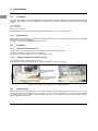
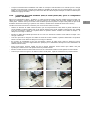
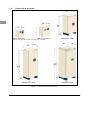
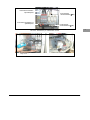
1.7. Handling
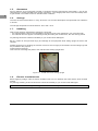
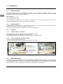
After having carefully unpacked the equipment, check that
the characteristics noted on the nameplates correspond to the ones specified in your purchase order.
the material does not appear to be damaged and particularly the central frame, the rear and top panels.
Any damage should be notified immediately to your closest local ABB agent.
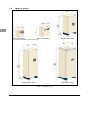
Be very careful to avoid personal injury and damage to the equipment while setting upright the boxes and
cubicles.
Suitable equipment for handling the cubicles such as a hoist is highly recommended. Use the lifting lugs that
are provided for this purpose.
Avoid shocks and bumps.
Take care not to damage the plinth of the cubicles while setting upright them.
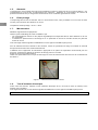
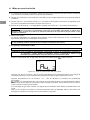
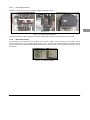
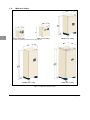
Figure 1.1. APCM and APCR setting upright
1.8. Electric insulation test
Before applying voltage, make an electric insulation test of 2.5 kV between the earth and the short-circuited
phases.
Any damage resulting of this test should be notified immediately to your closest local ABB agent.
WARNING: End this test by removing the short circuit of the phases.

APC - Chapter 2. APC description
9
en
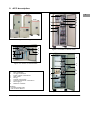
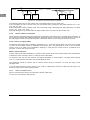
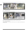
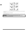
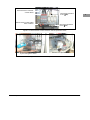
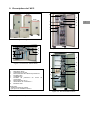
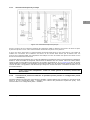
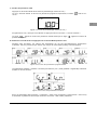
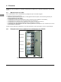
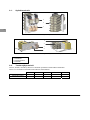
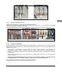
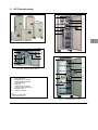
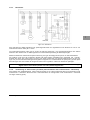
2. APC description
Figure 2.1. APC types
Figure 2.2. APCL2 of 125kvar/400V
1 LVCS capacitors
2 RVC controller *
3 UA type contactors
4 Power cables connections
5 HRC fuses
6 Fan(s)
7 Control circuit fuses
8 Current transformer connection *
9 Fan supply **
10 Reactors modules
Remarks:
*: in master cubicle only.
**: not for slave APCL2.
Figure 2.3. APCM2 of 400kvar/400V
Figure 2.4. APCR of 300kvar/400V
6
7
8
4
1
3
5
9
2
6
7
4
10
1
3
5
2
9
8
9
3
1
4
5
7
8
6
2
APCL1
APCL2
APCM1
APCM2
APCR

APC - Chapter 2. APC description
10
en
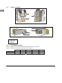
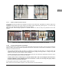
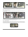
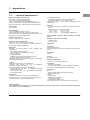
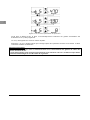
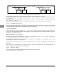
2.1. Power modules
2
3
1
Figure 2.5. Example of a front face and rear face (APCM module)
4
3
1
2
Figure 2.6. Example of a front face and rear face (APCR module)
1 Fuses
2 Contactors
3 Capacitors
4 Reactors
2.2. Ventilation system
APCL2, APCM1, APCM2 and APCR are provided with one or several fans.
APCL1 is provided with air grids allowing natural ventilation.
APCL1 APCL2 APCM1 APCM2
APCR
Fan(s) quantity
0 1 2 1
2
Fan(s) position
/ door top top
top

APC - Chapter 2. APC description
11
en
2.2.1. Thermistor
Each fan is of DC type and is equipped with its own thermistor.
This thermistor will adapt the speed of the fan (“variofan” type) to the APC internal temperature.
This fan operates from a 30°C temperature and delivers a maximum airflow for a 50°C temperature.
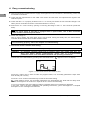
2.2.2. Temperature probe
Each APC cubicle is also equipped with a temperature probe in order to switch off the controller power
supply. In case of overtemperature around 60°C, the whole APC bank is automatically disconnected.
Figure 2.7. Temperature probe

APC - Chapter 3. Installation
12
en
3. Installation
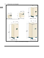
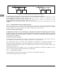
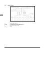
3.1. Location
The APC are suitable for indoor installation, on appropriate surfaces. Shelter the equipment from dust and
moisture and place it in a well-ventilated area where the ambient temperature doesn’t exceed the following
values:
40°C maximum;
35°C over 24h;
25°C over one year.
Appropriate action must be taken for ambient temperature down to -5°C or above 40°C.
3.2. Harmonics
The installation of capacitors on networks disturbed by harmonics may require special precautions especially
when there is a risk of resonance.
Consult your closest local ABB agent if it is the case.
3.3. Fixation
3.3.1. APCL1 and APCL2 boxes
Fix the boxes on the wall by means of the fixation kit provided for this purpose.
The ground clearance must be of 10 cm minimum.
It’s advised to keep a distance of 10 cm between the boxes.
3.3.2. APCM1, APCM2 and APCR cubicles
The cubicles must be placed on the ground.
Their backside must be positioned at a minimum distance of 5 cm from the wall.
V
iew of the air grids in
the bottom of each
cubicle
V
iew of the cable entry
plate in the bottom of
each cubicle
APCM
APC
R
Figure 3.1. Air grids and cable entry in APCM and APCR
3.4. Connection
Cabling of equipment requires three main power connection (no neutral required) to each unit, two control
wires from the current transformer to the master unit and, in case of master unit + slave unit configuration,
the wiring of the interconnection cable from the slave unit to the master unit. The interconnection cable is
factory wired in the slave unit.

APC - Chapter 3. Installation
13
en
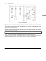
3.4.1. Electrical diagram
Figure 3.2. Electrical diagram
Regarding the standard wiring of the ABB controllers, the voltage reference for the controllers is taken from
L2 and L3 phases and the current transformer is sited on the L1 phase.
If the current transformer is sited on another phase, it’s useless to modify the voltage and current
connections since the APC bank is provided with an ABB controller with automatic adaptation to network
phase-rotation and CT terminals.
Master units are fitted with a power release contact which allows to remotely switch on and off the whole
APC bank. Before installing this feature, disconnect the whole APC bank from the power supply. In the
master unit, remove the connection wire (jumper) situated next to the gray CT jumper (see Figure 3.6.) in
order to switch off the power supply phase L2 of the PF controller. Connect the cable for remote control in
place of the considered jumper. Only when the contact is closed the PF controller is fed and the bank is
switched on.
WARNING: hazard of electrical shock: be sure that the APC isolating switchgear is open before
every manipulation. All units (master and slave) must be disconnected.
3.4.2. Connection of several banks in parallel (master units or master unit + slave unit
configuration)
Several banks can be connected in parallel. Each bank may consist of a single master unit or a master unit +
slave unit configuration. Please note that to obtain higher ratings (kvar) we recommend a master unit + slave
unit configuration.

APC - Chapter 3. Installation
14
en
BANK1
BANK2
CT1
TO LOAD
TO FEEDER
BANK1
BANK2
CT1
TO LOADTO FEEDER
CT2
Figure 3.3. Connection of several banks in parallel
The switching delay time of each master unit must slightly differ from the other ones.
If the controllers are set to normal mode, we recommend using a switching time delay difference of 1 sec.
(e.g. 40s, 41s, 42s, …)
If the controllers are set to integral mode, we recommend using a switching time delay difference of at least
21 sec. (e.g. 120s, 141s, 162s, …)
Note that each bank may include either a single master unit or a master unit plus a slave unit.
3.4.3. Power cables connection
When selecting the appropriate cable size due consideration should be given to possible future extension of
the equipment. Cables and isolating switchgear should be rated at 1.5 times the nominal capacitor current of
the total capacitor bank and should always be coordinated with the current rating of the back up fuses.
Cross section of supply cables
The different parameters like localization, temperature, etc… and other factors which may exist, do not allow
to cover all the possible cases of installation and simple rules. The standards in force in the concerned
country have to be taken into consideration keeping in mind that the current must be considered as a
minimum 1.5 times the nominal current.
Master switch and fuses
At the location of the bank installation, the power of the network short-circuit must be taken into consideration
to define the main connection fuses, or rating of the circuit breaker.
To disconnect the unit from the network, we suggest preferably a circuit breaker. A 3-phase disconnecting
fuse or a 3-phase switch with fuses may nevertheless be used.
The apparatus should be chosen with a nominal current rating of minimum 1.5 times the rating of the
capacitor bank.
It is to be noted however that the fuses, if any, must be calibrated to protect the cables and at least at 1.6
times the rating current of the capacitor bank.
3.4.3.1. APCL1 and APCL2 boxes
APCL1 and APCL2 are factory mounted with a bottom cable entry.
A knock out is provided for this purpose.

APC - Chapter 3. Installation
15
en
APCL1 APCL2
Figure 3.4. Power cables connection to the incoming power terminals for boxes
3.4.3.2. APCM1, APCM2 and APCR cubicles
The APCM and APCR cubicles are available in bottom or top cable entry. By default, the bottom cable entry
is applied.
The plate at the bottom left of the cubicle is provided to allow cable entry (see Figure 3.1.) In case of top
cable entry, use the two other plates at the top of the cubicle.
Run the power cable through a gland of a suitable diameter in order to keep the protection level of the
cubicle.
APCM1 APCM2 APCR
(bottom cable entry on the picture) (bottom cable entry on the picture) (top or bottom cable entry)
Figure 3.5. Power cables connection to the incoming power terminals for cubicles
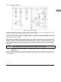
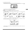
3.4.4. Current transformer connection
Current transformers of Class 1 accuracy and appropriate burden with secondary current 5A will normally be
used. In case CT and the automatic capacitors are close to each other a 5VA burden is sufficient if no other
loads are connected to the CT.
The current transformer must be sited in a position to monitor the total load (i.e. inductive load and
capacitive load). This will normally be close to the incoming supply metering position. A range of ring and
split core CTs exists on the market to ease installation.
Current transformers are normally marked P1/P2 and S1/S2 and should be positioned so that P1 faces
the incoming supply while P2 faces the load side.
Control wires from S1 terminal go to terminal marked
k on the circuit diagram and from S2 to
terminal marked
l on the diagram. Once the connection is made, the shorting link (gray jumper)
must be removed for proper operation.
To easy guide control wires, a cable profile is fixed in each box.
Each cubicle has several base supports on its central frame to receive cable ties.

APC - Chapter 3. Installation
16
en
Gray jumper to short-circuit the
CT secondary winding
Power release contact fo
r
remote control
Figure 3.6. CT connection and release contact
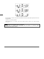
When a multi ratio split core C.T. is used the appropriate ratio is selected by connecting either S2 or S3 or
S4 to terminal marked
l. The C.T. ratio should be selected as near as possible to suit the supply loading.
Figure 3.7. Multi ratio CT
When a summation current transformer is used the terminal markings will usually be P1, P2, P3, P4 and
S1, S2. The secondary connections S1 and S2 should be made to
k and l respectively as before.
Figure 3.8. Summation CT
The first C.T. should be connected with S1 and S2 to P1 and P2 on the summation C.T. while the second
C.T. should be connected with S1 and S2 to P3 and P4 on the summation C.T. It is important that all CTs
monitor current in the same direction.
When a summation C.T. is used or the CT monitors only part load (i.e. two cables per phase with the C.T.
on one cable only) the total system current that gives 5A in the relay current coil is used to calculate relay
setting.

APC - Chapter 3. Installation
17
en
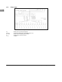
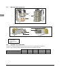
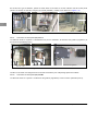
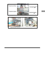
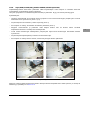
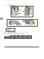
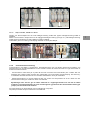
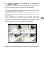
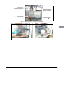
3.4.5. Slave (AUX) to master (PIL) unit connection (for master unit + slave unit
configuration)
In a master unit + slave unit configuration an interconnection cable must be installed between the units. This
cable is factory wired in the slave unit and allows a full control of the slave unit from the master unit. Note
that only one slave unit can be added to each master unit and the slave unit must be of the same type
(APCL2 with APCL2, APCM2 with APCM2 and APCR with APCR).
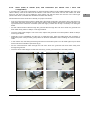
Please follow the below instruction carefully for proper connection:
Free and unwind the interconnection cable that is temporally arranged in the bottom part of the slave unit.
Take away the black grommet from the bottom plate of the enclosure. Beware the grommet shape is not
symmetrical hence look at its orientation (and even tag it). Please refer to Step 1 and Step 2 on the figure
below.
Put the interconnection cable through the grommet then through the hole from which the grommet has
been taken away. Refer to Step 3 on the figure below.
Once the whole cable length is out of the units, replace the grommet to its initial position. Refer to Step 4
on the figure below.
Depending on the installation and the type of capacitor bank, pass the cable below the enclosure or
behind the plinth. Always follow good practice of electrical installation when installing the interconnection
cable.
In the master unit, take away the black grommet from the bottom plate. You will need again to put it back
hence look at its orientation (and even tag it).
Put the interconnection cable through the hole from which the grommet has been taken away then
through the grommet.
Once the whole cable length is inside the enclosure, put the grommet back to its initial position.
Step 1 Step 2
Step 3 Step 4
Figure 3.9. Slave to master unit connection

APC - Chapter 3. Installation
18
en
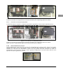
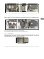
Depending on the type of the bank, pass the cable inside the right hand side raceway (APCL2 and APCR) or
fix it along the central plate (APCM2). Please refer to Figure 3.10.
APCL2 APCM2 APCR
Figure 3.10. Interconnection cable location
3.4.5.1. Master (PIL) APCL2 wiring
The cable is divided in three main parts: the DC supply for the fan (to DC supply unit), the step control (to the
PF controller) and special features (to a dedicated terminal).
Special features connection DC supply connection PF controller connection
(terminal labels: X, 15)
Figure 3.11. Master APCL2 wiring
Please revert to the schematic diagrams fitted with the bank for exact label of the wires.
3.4.5.2. Master (PIL) APCM2 wiring
The cable is divided in two main parts: the step control (to the PF controller) and special features (to a
dedicated terminal).

APC - Chapter 3. Installation
19
en
Special features connection Special features connection PF controller connection
(terminal labels: X, 15, A)
Figure 3.12. Master APCM2 wiring
Please revert to the schematic diagrams fitted with the bank for exact label of the wires.
3.4.5.3. Master (PIL) APCR wiring
The cable is divided in two main parts: the step control (to the PF controller) and special features (to a
dedicated terminal).
Special features connection Special features connection PF controller connection
(terminal labels: X, 15, A)
Figure 3.13. Master APCR wiring
Please revert to the schematic diagrams fitted with the bank for exact labels of the wires.
After wiring, please check that the cable is properly fixed in the bank.
3.4.6. Earth connection
The APCL earth connections are made by means of a stud (∅ M6). This one is welded inside the APCL in
the lower right corner. The door is already connected to this stud. It only remains to connect the earth wire if
the power cable is fitted with it. For the APCM and APCR, the earth connection can be made by means of
one of the two stud (∅ M8) located in the upper and lower left corners.
Figure 3.14. Earth connection

APC - Chapter 4. Easy commissioning
20
en
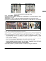
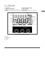
4. Easy commissioning
1. With the equipment isolated from the supply check tightness of all connections, earth bonding, fuses, free
movement of contactors.
2. Check that the requirements for the cable cross section and the fuses are respected with regard to the
total bank power.
3. Check that the C.T. is properly located on line L1 i.e. the only line where the PF Controller voltage is not
taken (The PF Controller should be connected between L2 and L3).
4. Remove the C.T. short circuit by opening or removing the bridge of the C.T. wire connector (inside the
bank).
Note:
The APC is normally equipped with an RVC controller. To carry on with this commissioning,
follow the points below. If your APC is equipped with an optional RVT, refer to RVT instruction
manual and don’t follow the points below.
5. Switch the voltage on.
After a power outage, the reset delay time is 40 seconds. During this delay time, the disconnection
indication blinks and the alarm contact remains closed.
Check that all the fans are in good working order.
If it’s not working properly, refer to the Chapter 5. Troubleshooting.
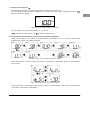
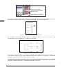
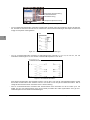
6. RVC Power Factor Controller auto setting.
WARNING: if several units are connected in parallel, please refer to 3.4.2.
WARNING: for automatic capacitor banks with a switching delay time greater than 40s., set
delay time before starting commissioning. Please refer to § Programmable
parameters and to 10.4. of the RVC Installation and operating instructions.
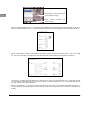
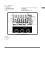
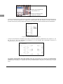
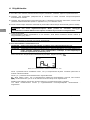
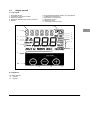
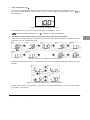
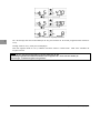
Activate the AUTO SET Mode by pressing twice the Mode button. “
” appears on the LCD display.
Figure 4.1. View of the AUTO SET mode in RVC
Press the + button once in order to make only appear Phase, C/k, and Delay parameters. Steps have
been already set in factory.
Press the + and – buttons simultaneously to start the automatic setting.
“
” starts flashing. Phase, C/k and Delay parameters are automatically set. Note that the delay value
remains unchanged if it is set above or equal to 40 sec. before commissioning.
If an error is detected, the AUTO SET procedure is stopped and an error message is displayed.
In this case, refer to the RVC Installation and operating instructions, § Error messages for a complete
description of error messages and solutions.
Sidan laddas...
Sidan laddas...
Sidan laddas...
Sidan laddas...
Sidan laddas...
Sidan laddas...
Sidan laddas...
Sidan laddas...
Sidan laddas...
Sidan laddas...
Sidan laddas...
Sidan laddas...
Sidan laddas...
Sidan laddas...
Sidan laddas...
Sidan laddas...
Sidan laddas...
Sidan laddas...
Sidan laddas...
Sidan laddas...
Sidan laddas...
Sidan laddas...
Sidan laddas...
Sidan laddas...
Sidan laddas...
Sidan laddas...
Sidan laddas...
Sidan laddas...
Sidan laddas...
Sidan laddas...
Sidan laddas...
Sidan laddas...
Sidan laddas...
Sidan laddas...
Sidan laddas...
Sidan laddas...
Sidan laddas...
Sidan laddas...
Sidan laddas...
Sidan laddas...
Sidan laddas...
Sidan laddas...
Sidan laddas...
Sidan laddas...
Sidan laddas...
Sidan laddas...
Sidan laddas...
Sidan laddas...
Sidan laddas...
Sidan laddas...
Sidan laddas...
Sidan laddas...
Sidan laddas...
Sidan laddas...
Sidan laddas...
Sidan laddas...
Sidan laddas...
Sidan laddas...
Sidan laddas...
Sidan laddas...
Sidan laddas...
Sidan laddas...
Sidan laddas...
Sidan laddas...
Sidan laddas...
Sidan laddas...
Sidan laddas...
Sidan laddas...
Sidan laddas...
Sidan laddas...
Sidan laddas...
Sidan laddas...
Sidan laddas...
Sidan laddas...
Sidan laddas...
Sidan laddas...
Sidan laddas...
Sidan laddas...
Sidan laddas...
Sidan laddas...
Sidan laddas...
Sidan laddas...
Sidan laddas...
Sidan laddas...
Sidan laddas...
Sidan laddas...
Sidan laddas...
Sidan laddas...
Sidan laddas...
Sidan laddas...
Sidan laddas...
Sidan laddas...
Sidan laddas...
Sidan laddas...
Sidan laddas...
Sidan laddas...
-
 1
1
-
 2
2
-
 3
3
-
 4
4
-
 5
5
-
 6
6
-
 7
7
-
 8
8
-
 9
9
-
 10
10
-
 11
11
-
 12
12
-
 13
13
-
 14
14
-
 15
15
-
 16
16
-
 17
17
-
 18
18
-
 19
19
-
 20
20
-
 21
21
-
 22
22
-
 23
23
-
 24
24
-
 25
25
-
 26
26
-
 27
27
-
 28
28
-
 29
29
-
 30
30
-
 31
31
-
 32
32
-
 33
33
-
 34
34
-
 35
35
-
 36
36
-
 37
37
-
 38
38
-
 39
39
-
 40
40
-
 41
41
-
 42
42
-
 43
43
-
 44
44
-
 45
45
-
 46
46
-
 47
47
-
 48
48
-
 49
49
-
 50
50
-
 51
51
-
 52
52
-
 53
53
-
 54
54
-
 55
55
-
 56
56
-
 57
57
-
 58
58
-
 59
59
-
 60
60
-
 61
61
-
 62
62
-
 63
63
-
 64
64
-
 65
65
-
 66
66
-
 67
67
-
 68
68
-
 69
69
-
 70
70
-
 71
71
-
 72
72
-
 73
73
-
 74
74
-
 75
75
-
 76
76
-
 77
77
-
 78
78
-
 79
79
-
 80
80
-
 81
81
-
 82
82
-
 83
83
-
 84
84
-
 85
85
-
 86
86
-
 87
87
-
 88
88
-
 89
89
-
 90
90
-
 91
91
-
 92
92
-
 93
93
-
 94
94
-
 95
95
-
 96
96
-
 97
97
-
 98
98
-
 99
99
-
 100
100
-
 101
101
-
 102
102
-
 103
103
-
 104
104
-
 105
105
-
 106
106
-
 107
107
-
 108
108
-
 109
109
-
 110
110
-
 111
111
-
 112
112
-
 113
113
-
 114
114
-
 115
115
-
 116
116


ABB APCM2 Installation, Operation And Maintenance Instructions
- Typ
- Installation, Operation And Maintenance Instructions
- Denna manual är också lämplig för
Andra dokument
-
Brodit 215568 Datablad
-
Cebora WIN TIG DC 250 T Användarmanual
-
APC Performance SA 8 Tel/TV, GR Specifikation
-
APC SurgeArrest Essential Specifikation
-
APC PM6-GR Specifikation
-
APC PM5U-GR Specifikation
-
APC PM5B-RS Användarmanual
-
APC Essential SA 5 GR Promo Specifikation
-
 Onninen HID HPL-SON Användarmanual
