
DE Drechselmaschine
Original-Anleitung
GB Wood Turning Lathe
Translation from the original instruction manual
FR Tour à bois
Traduction du manuel d’origine
IT Tornio
Traduzione dalle istruzioni d’uso originali
NL Draaibankmachine
Vertaling van originele handleiding
ETorno
Traducción de la instrucción de original
PT Máquina de tornear
Tradução do manual de instruções original
SE Svarv
Översättning av original-bruksanvisning
FIN Puusorvi
Käännös alkuperäisestä käyttöohjeesta
NO Tredreiebank
Oversettelse fra original brukermanual
DK Drejebænk
Oversættelse fra den originale brugervejledning
CZ Soustruh na dřevo
Překlad originálního návodu k obsluze
SK Sústruh
Preklad originálu návodu na obsluhu
HU Esztergagép
Az eredeti útmutató fordítása
Art.Nr.
1902301901 / 1902301903
AusgabeNr.
1902301850
Rev.Nr.
23/08/2017
Lata 5.0
www.scheppach.com service@scheppach.com +(49)-08223-4002-99 +(49)-08223-4002-58
Nachdrucke, auch auszugsweise, bedürfen der Genehmigung. Technische Änderungen vorbehalten. Abbildungen beispielhaft!

Fig. 2Fig 1.2
A
CD
3
145
15
9
14
13
10
11 2
Fig 1.1
12
6
8
7

Fig. 3 Fig. 4
Fig. 5 Fig. 6
Fig. 7 Fig. 8
Klemmgriff
Rastbolzen

Fig. 11
Fig. 9 Fig. 10
Fig. 12
L
N
PE
L 0 R
L1
Z2
L2
Z1
2
1
Motor
Switch
Fig. 13

6 - 11
12 - 16
17 - 22
23 - 28
29 - 34
35 - 39
40 - 44
45 - 49
50 - 54
55 - 59
60 - 64
65 - 69
70 - 74
75 - 80
D
GB
FR
IT
E
PT
SE
FIN
NL
NO
DK
CZ
SK
HU

6 deutsch
Hersteller:
Scheppach
Fabrikation von Holzbearbeitungsmaschinen GmbH
Günzburger Straße 69
D-89335 Ichenhausen
Verehrter Kunde,
Wir wünschen Ihnen viel Freude und Erfolg beim Arbei-
ten mit Ihrer neuen scheppach Maschine.
Hinweis:
Der Hersteller dieses Gerätes haftet nach dem geltenden
Produkthaftungsgesetz nicht für Schäden, die an diesem
Gerät oder durch dieses Gerät entstehen bei:
• unsachgemäßer Behandlung,
• Nichtbeachtung der Bedienungsanweisung,
• Reparaturen durch Dritte, nicht autorisierte Fachkräfte,
• Einbau und Austausch von nicht originalen Ersatz-
teilen,
• nicht bestimmungsgemäßer Verwendung,
• Ausfällen der elektrischen Anlage bei Nichtbeachtung
der elektrischen Vorschriften und VDE-Bestimmungen
0100, DIN 57113 / VDE0113.
Wir empfehlen Ihnen:
Lesen Sie vor der Montage und vor Inbetriebnahme den
gesamten Text der Bedienungsanweisung durch.
Diese Bedienungsanweisung soll es Ihnen erleichtern,
Ihre Maschine kennenzulernen und ihre bestimmungs-
gemäßen Einsatzmöglichkeiten zu nutzen.
Die Bedienungsanweisung enthält wichtige Hinweise,
wie Sie mit der Maschine sicher, fachgerecht und wirt-
schaftlich arbeiten, und wie Sie Gefahren vermeiden,
Reparaturkosten sparen, Ausfallzeiten verringern und
die Zuverlässigkeit und Lebensdauer der Maschine er-
höhen.
Zusätzlich zu den Sicherheitsbestimmungen dieser Be-
die nungsanweisung müssen Sie unbedingt die für den
Be trieb der Maschine geltenden Vorschriften Ihres Lan-
des beachten.
Die Bedienungsanweisung, in einer Plastikhülle ge-
schützt vor Schmutz und Feuchtigkeit, bei der Maschi-
ne aufbe wah ren. Sie muss von jeder Bedienungsperson
vor Auf nah me der Arbeit gelesen und sorgfältig beachtet
werden. An der Maschine dürfen nur Personen arbeiten,
die im Ge brauch der Maschine unterwiesen und über die
damit verbundenen Gefahren unterrichtet sind. Das ge-
forderte Mindestalter ist einzuhalten.
Allgemeine Hinweise
• Überprüfen Sie nach dem Auspacken alle Teile auf
even tu elle Transportschäden. Bei Beanstandungen
muss so fort der Zubringer verständigt werden. Spätere
Reklamationen werden nicht anerkannt.
• Überprüfen Sie die Sendung auf Vollständigkeit.
• Machen Sie sich vor dem Einsatz anhand der Be die-
nungs anweisung mit dem Gerät vertraut.
• Verwenden Sie bei Zubehör sowie Verschleiß- und Er-
satzteilen nur Original-Teile. Ersatzteile erhalten Sie
bei Ihrem scheppach-Fachhändler.
• Geben Sie bei Bestellungen unsere Artikelnummern
so wie Typ und Baujahr des Gerätes an.
Lata 5.0
Lieferumfang
Drechselmaschine
Werkzeugauage
Mitnehmer (Fig. 1.2, A)
Reitstockspitze
Stößel (Fig. 1.2, C)
Planscheibe
Gabelschlüssel SW 32 (Fig. 1.2, D)
Bedienungsanweisung
Technische Daten
Baumaße
L x B x H mm 1610 x 490 x 1175
Betthöhe 910
Spindelkopfgewinde Art. Nr. 8800 1925 (1" x 8 TPI)
Art. Nr. 8800 1926 (M 33)
Spindelkopfkonus MK 2
Spitzenhöhe über Bett
mm 175
Spitzenweite mm 1050
Durchmesser über Bett
mm 355
Durchmesser zwischen
Spitzen mm 282
Werkzeugauagelänge
mm 300
Planscheibe ø mm 150
Gewicht kg 92
Drechselspindel mit staubdichten Präzisions-
Rillenkugellagern
Drehzahl 1/min 500/600/750/900/1100/
1200/1400/1600/1800/2100
Reitstock
Reitstockkonus MK 2
Reitstockbohrung
(Hohlspindel) ø mm 9
Pinolenver-stellung mm 55
Antrieb
Elektromotor 230–240V/50 Hz
Aufnahmeleistung P1
kW 0,75
Abgabeleistung P2 kW 0,50
Drehzahl 1/min 1400
Motorschutz ja
Unterspannungs-
auslösung ja
Schalter-Stecker-
Kombination Netzstecker
Betriebsart S6 40%
Geräuschkennwerte
Die nach EN 23746 für den Schalleistungspegel bzw.
EN 31202 (Korrektorfaktor k3 nach Anhang A.2 von EN
31204 berechnet) für den Schalldruckpegel am Arbeits-
platz ermittelten Geräuschemissionswerte betragen
unter Zu grundelegung der in ISO 7904 Anhang A aufge-
führten Arbeits bedingungen.
Schalleistungspegel in dB
Leerlauf LWA = 81,9 dB(A), Bearbeitung LWA = 84,5 dB(A)
Schalldruckpegel am Arbeitsplatz in dB
Leerlauf LpAeq = 72,4 dB(A),
Bearbeitung LpAeq = 76,2 dB(A)
Für die genannten Emissionswerte gilt ein
Meßunsicher heitszuschlag K = 4 dB.
Technische Änderungen vorbehalten!

deutsch 7
Legende (Fig. 1.1)
1. Spindelstock
2. Planscheibe
3. Werkzeugauage mit Exzenterklemmung
und Klemmhebel
4. Reitstockspitze
5. Klemmgriff
6. Reitstock
7. Exzenter-Klemmhebel
(auf der Rückseite des Reitstocks)
8. Drechselbett
9. Ein/Ausschalter
10. Drehrichtungsschalter
11. Einstellhebel für Drehzahl
12. Klemmhebel für Spindelstock
13. Gestellfüße
14. Fußplatten
15. Gestellwanne
m Allgemeine Sicherheitshinweise
In dieser Bedienungsanweisung haben wir Stellen,
die Ihre Sicherheit betreffen, mit diesem Zeichen
versehen m
• Geben Sie die Sicherheitshinweise an alle Personen
weiter, die an der Maschine arbeiten.
• Alle Sicherheits- und Gefahrenhinweise an der Ma-
schine vollzählig in lesbarem Zustand halten.
• Netzanschlussleitungen überprüfen.Keine fehlerhaf-
ten Leitungen verwenden.
• Achten Sie darauf, dass die Maschine standsicher auf
festem Grund steht.
• Vorsicht beim Arbeiten: Verletzungsgefahr für Finger,
Hände und Augen.
• Halten Sie Kinder von der an das Netz angeschlosse-
nen Maschine fern.
• Beim Arbeiten an der Maschine müssen sämtliche
Schutzeinrichtungen und Abdeckungen montiert sein.
• Die Bedienungsperson muss mindestens 18 Jahre alt
sein. Auszubildende müssen mindestens 16 Jahre alt
sein, dürfen aber nur unter Aufsicht an der Maschine
arbeiten.
• An der Maschine tätige Personen dürfen nicht abge-
lenkt werden.
• Den Bedienplatz der Maschine von Spänen und Holz-
abfällen freihalten.
• Eng anliegende Kleidung tragen. Schmuck, Ringe und
Armbanduhren ablegen.
• Zum Schutz von langem Kopfhaar Mütze oder Haar-
netz aufsetzen.
• Keine Arbeitshandschuhe tragen.
• Beim Arbeiten Schutzbrille tragen.
• Die Motordrehrichtung beachten – siehe Elektrischer
Anschluss.
• Die richtige Drehzahleinstellung an der Maschine be-
achten.
• Die Sicherheitseinrichtungen an der Maschine dürfen
nicht demontiert oder unbrauchbar gemacht werden.
• Umrüst-, Einstell-, Mess- und Reinigungsarbeiten nur
bei ausgeschaltetem Motor durchführen. Netzstecker
ziehen und Stillstand des rotierenden Werkzeuges ab-
warten.
• Zum Beheben von Störungen die Maschine abschal-
ten. Netzstecker ziehen.
• Installationen und Wartungsarbeiten an der Elektroins-
tallation dürfen nur von Fachleuten ausgeführt werden.
• Sämtliche Schutz- und Sicherheitseinrichtungen müs-
sen nach abgeschlossenen Reparatur- und Wartungs-
arbeiten sofort wieder montiert werden.
• Die Werkzeugauage so dicht wie möglich an das
Werkstück heranstellen.
• Bei Werkstücken aus Holz darf die Umfanggeschwindig-
keit max. 25 m/s betragen. Spindeldrehzahlschaubild
beachten!
• Die Spindeldrehrichtung beachten – s. Wendeschalter.
• Werkstücke vor dem Spannen zwischen Spitzen beid-
seitig mit Zentrierbohrung versehen
• Groß und unwuchtige Werkstücke nur mit kleiner Dreh-
zahl bearbeiten und evtl. vorher auf der Bandsäge ent-
sprechend beschneiden.
• Rissige Werkstücke dürfen nicht verwendet werden.
• Vor dem Einschalten der Maschine ist die sichere Ein-
spannung des Werkstückes zu überprüfen
• Spannschlüssel oder Spannstifte vor dem Einschal-
tend der Maschine abziehen
• Riemenabdeckung immer schließen.
• Arbeiten mit Drei- oder Vierbackenfutter dürfen nur mit
montiertem Backenfutterschutz ausgeführt werden.
• Auslaufende Werkstücke nie von Hand abbremsen.
Messungen nie am rotierenden Werkstück vornehmen.
• Nur mit gut geschärften Werkzeugen arbeiten.
• Drechselwerkzeug immer mit beiden Händen führen.
• Die richtige Drehzahleinstellung beach ten.
• Beim Verlassen des Arbeitsplatzes den Motor aus-
schalten. Netzstecker ziehen.
• Auch bei geringfügigem Standortwechsel Maschi-
ne von jeder externen Energiezufuhr trennen! Vor
Wiederinbe trieb nahme die Maschine ordnungsgemäß
an das Netz anschließen!
Warnung! Dieses Elektrowerkzeug erzeugt während
des Betriebs ein elektromagnetisches Feld. Dieses Feld
kann unter bestimmten Umständen aktive oder pas-
sive medizinische Implantate beeinträchtigen. Um die
Gefahr von ernsthaften oder tödlichen Verletzungen zu
verringern, empfehlen wir Personen mit medizinischen
Implantaten ihren Arzt und den Hersteller vom medizini-
schen Implantat zu konsultieren, bevor das Elektrowerk-
zeug bedient wird.
m Bestimmungsgemäße Verwendung
• Die Maschine entspricht der gültigen EG Maschinen-
richtlinie.
• Maschine nur in technisch einwandfreiem Zustand so-
wie bestimmungsgemäß, sicherheits- und gefahren-
bewusst unter Beachtung der Betriebsanleitung
benut zen! Insbesondere Störungen, die die Sicherheit
beein trächtigen können, umgehend beseitigen (las-
sen)!
• Die scheppach-Drechselmaschine ist ausschließlich
zum Bearbeiten von Holz gebaut.
• Jeder darüber hinausgehende Gebrauch gilt als nicht
bestimmungsgemäß. Für daraus resultierende Schä-
den haftet der Hersteller nicht; das Risiko dafür trägt
allein der Benutzer.
• Die Sicherheits-, Arbeits- und Wartungsvorschriften
des Herstellers sowie die in den Technischen Daten
an gegebenen Abmessungen müssen eingehalten
wer den.
• Die zutreffenden Unfallverhütungsvorschriften und die
sonstigen, allgemein anerkannten sicherheitstechni-
schen Regeln müssen beachtet werden.

8 deutsch
• Die Maschine darf nur von Personen genutzt, gewar-
tet oder repariert werden, die damit vertraut und über
die Gefahren unterrichtet sind. Eigenmächtige Ver än-
derungen an der Maschine schließen eine Haftung des
Herstellers für daraus resultierende Schäden aus.
• Die Maschine darf nur mit Originalzubehör und -werk-
zeugen des Herstellers genutzt werden.
Bitte beachten Sie, dass unsere Geräte bestimmungs-
gemäß nicht für den gewerblichen, handwerklichen oder
industriellen Einsatz konstruiert wurden. Wir übernehmen
keine Gewährleistung, wenn das Gerät in Gewerbe-,
Handwerks- oder Industriebetrieben sowie bei gleichzu-
setzenden Tätigkeiten eingesetzt wird.
m Restrisiken
Die Maschine ist nach dem Stand der Technik und
den an erkannten sicherheitstechnischen Regeln ge-
baut. Dennoch können beim Arbeiten einzelne Rest-
risiken auftreten.
• Verarbeiten Sie nur ausgesuchte Hölzer ohne Fehler
wie: Ast stellen, Querrisse, Oberächenrisse. Fehler-
haftes Holz neigt zum Splittern und wird zum Risiko
beim Arbeiten.
• Nicht sorgfältig verleimte Hölzer können aufgrund der
Zentrifugalkraft beim Bearbeiten explodieren.
• Vor dem Einspannen das rohe Werkstück auf Quadrat-
form zuschneiden, zentrieren und auf sichere Einspan-
nung achten. Umwucht im Werkstück führt zu Verlet-
zungs gefahr.
• Verletzungsgefahr durch unsichere Werkzeugfüh-
rung bei nicht exakt angestellter Werkzeugauage
und stumpfem Drechselwerkzeug. Voraussetzung für
fachgerechtes Drechseln ist einwandfreies, scharf ge-
schliffenes Drech sel werkzeug.
• Gefährdung der Gesundheit durch das rotierende
Werkstück bei langem Kopfhaar und loser Kleidung.
Per sönliche Schutzausrüstung wie Haarnetz und eng
anliegende Kleidung tragen.
• Gefährdung der Gesundheit durch Holzstäube oder
Holz späne. Persönliche Schutzausrüstungen wie Au-
genschutz und Staubmaske tragen.
• Gefährdung der Gesundheit durch Strom bei Verwen-
dung nicht ordnungsgemäßer Elektro-Anschlusslei-
tungen.
• Desweiteren können trotz aller getroffener Vorkehrun-
gen nicht offensichtliche Restrisiken bestehen.
• Restrisiken können minimiert werden, wenn die „Si-
cherheitshinweise“ und die „Bestimmungsgemäße
Ver wendung“, sowie die Bedienungsanweisung insge-
samt beachtet werden.
Montage (Fig. 2 – 5)
Aus verpackungstechnischen Gründen ist Ihre Drechsel-
maschine teilmontiert.
• Fig. 2: Die Gestellfüße paarweise mit dem oberen
Gestell winkel leicht verschrauben, (je 3 Flachrund-
schrauben M8 x 12 mit Scheibe und Mutter), Fußplat-
ten aufsetzen.
• Fig 3: Gestellwanne mit Gestellfüßen ebenfalls nur
handfest verschrauben (je 2 Flachrundschrauben M8
x 12 mit Scheibe und Mutter).
• Stellen Sie das Gestell auf eine ebene Fläche.
• Fig 4: Die Drechselmaschine auf das Gestell aufset-
zen und mit den 8 Inbusschrauben M8 x 35, mit Feder-
ring und Mutter, fest verschrauben.
• Abschließend sämtliche Schrauben des Gestells fest
an ziehen.
• Fig. 5: Schalter in den Gestellfuß von innen einsetzen
und mit den Kreuzschlitzschrauben M4 mit Scheibe
und Mutter verschrauben.
Inbetriebnahme
Beachten Sie vor der Inbetriebnahme die
Sicherheitshin weise in der Bedienungsanweisung.
Vor Inbetriebnahme Spanndorne oder Schlüssel von
Spin del oder Aufspannwerkzeugen entfernen!
Wendeschalter, Fig. 6
Ihre Drechselmaschine ist mit einem Wendeschalter aus-
gestattet. Das Ein- und Ausschalten des Motors erfolgt
immer über den Betriebsschalter. I = grün; 0 = rot.
Der Wendeschalter ist nur ein „Wahlschalter“ für die
Dreh richtung. Sie können für die entsprechenden Ar-
beiten die Drehrichtung von links nach rechts
verändern.
Wichtig: Das Verändern der Drehrichtung darf nur bei
Stillstand des Motors erfolgen: Motor ausschalten –
Dreh richtung ändern – Motor einschalten.
Aus Sicherheitsgründen ist bei laufendem Motor ein
Umschalten der Drehrichtung nicht möglich. Der Wende-
schalter schaltet in 0-Stellung den Motor aus, sodass
er am grünen Schaltknopf erneut in Betrieb genommen
wer den muss.
Drehzahleinstellung
Die Drehzahleinstellung ist nur bei laufendem Motor vor-
zunehmen!
Die richtige Drehzahl ist auf dem Drehzahldiagramm am
Spindelstock ersichtlich.
Das Drehzahldiagramm ist für mittelharte trockene Höl-
zer ausgelegt.
Die geeignete Drehzahl richtet sich nach verschiedenen
Faktoren wie:
• Art und Beschaffenheit der Hölzer
• Abgelagerte, trockene Hölzer
• Durchmesser und Länge der Werkstücke
• Kantige oder unwuchtige Hölzer
• Breite vorgedrechselte, wuchtige Werkstücke.
• Drechselwerkzeuge, Drechseltechnik
• Werkstücke aus verleimten Hölzern
Erfolgreiches Drechseln hängt nicht von hohen Dreh zah-
len ab, sondern von der richtigen Anwendung der Drech-
selwerkzeuge.
Richtlinien zur Drehzahleinstellung
Niedrige Drehzahl für:
• Werkstücke mit großem Durchmesser
• Harte Werkstücke mit großem Durchmesser
• Lange, unwuchtige Werkstücke
• Verleimte Hölzer
Drehzahleinstellung (Fig. 7)
• Die Drehzahlverstellung ist stets bei eingeschalteter
Maschine vorzunehmen.
• Durch Ziehen rastet der Hebel aus und kann in die ge-
wünschte Stufe gedreht werden, in der der Hebel wie-
der einzurasten ist.

deutsch 9
Wichtig: stellen Sie vor dem Aufspannen eines neu-
en Werk stückes den Durchmesser des Werkstückes
fest und dem entsprechend die Drehzahl gemäß dem
Drehzahl diagramm ein. Bei unwuchtigen oder sehr gro-
ßen Werkstücken wählen Sie mindestens 1 Stufe kleiner.
Mitnehmer, Fig. 1.2, A
Der Mitnehmer wird ausschließlich für Arbeiten „zwi-
schen den Spitzen“ eingesetzt.
Planscheibe, Fig. 1.1
Die Planscheibe wird bei achen größeren Werkstücken
ver wendet.
Wechsel der Aufspannwerkzeuge
• Gewindestift am Schaft des Aufspannwerkzeugs lö-
sen.
• Spindel mit Sechs kant schlüssel festhalten, Aufspann-
werkzeug mit Sechs kant schlüssel lösen.
Spindelstock, Fig. 8
• Der Spindelstock läßt sich nach Lösen des Klemmgrif-
fes und Ziehen des Rastbolzens bis zu 180° schwen-
ken (Einrastpositionen 60°/90°/135°/180°).
• In jeder Position ist der Spindelstock wieder zu klem-
men.
• Der Spindelstock muss in der gelösten Stellung
auf dem Drechselbett ausgerichtet werden, um die
Werkzeug au age von links auf den Reitstock zu mon-
tieren.
• In diesen Positionen haben Sie die Möglichkeit, Werk-
stücke mit größeren Durchmesser zu bearbeiten.
Reitstock
• Der Reitstock ist nach Lösen der Exzenterklemmung
über die gesamte Bettlänge verstellbar und kann in je-
dem Abstand zum Spindelstock geklemmt werden.
• Zum Spannen eines Werkstückes zwischen den
Spitzen der Klemmgriff lösen, die Pinole ca. 20 mm
heraus dre hen und klemmen.
• Den Reitstock an das Werkstück anstellen und die
Reit stockspitze in den vertieften Mittpunkt setzen.
• Die Reitstockpinole soweit herausdrehen, bis die Reit-
stock spitze fest im Holz sitzt. Den Klemmgriff wie der
anziehen.
• Das Werkstück von Hand drehen und prüfen, ob das
Werk stück fest zwischen den Spitzen sitzt und sich frei
dre hen läßt
Reitstockspitze auswechseln, Fig. 1.1, 4
• Klemmgriff (5) lösen.
• Reitstockpinole ganz zurückdrehen, bis die Spitze ab-
nehm bar ist.
Werkzeugauage, Fig. 9, 10
• Die Werkzeugauage dient zur sicheren Führung der
Drechselwerkzeuge und ist zugleich Stütze für die
Hand. Die Höhenverstellung der Werkzeugauage er-
folgt nach Lösen des Klemmhebels. Zum Weiterdre-
hen in Pfeil richtung ziehen.
• Die Werkzeugauage im Abstand von 1 – 3 mm an das
Werkstück anstellen. Die Einstellung prüfen, dazu das
Werkstück von Hand drehen.
• Die Werkzeugauage ca. 3 mm oberhalb der Werk
stück achse anstellen. Die Einstellung erneut prüfen,
indem Sie das Werkstück wieder von Hand drehen.
• Nach Lösen der Exzenterklemmung ist die Auage
kon so le in Längsrichtung über die gesamte Bettlänge
und die Querrichtung bis an das Werkstück verstellbar.
Desweiteren ist die Auangkonsole nach beiden Sei-
ten über ca. 45° schwenkbar.
• Zur Bearbeitung einer Planäche die Werkzeugauage
90° drehen und an die zu bearbeitende Fläche anstel-
len. Je nach Drechselwerkzeug die Werkzeugauage
bis 6 mm unterhalb der Werkstückachse anstellen.
• Wird der Spindelkopf geschwenkt, so ist die Werkzeug-
auage mit der Verlängerung zu verwenden (Fig. 11).
• Hierzu wird diese links vom Spindelstock eingesetzt,
so dass nun größere Scheiben bearbeitet werden kön-
nen.
Werkzeugführung, Fig. 11
Beispiele der Werkzeugführung beim Bearbeiten der
häugsten Grundformen. Nach Anschluss an das Strom-
netz ist die Drechselmaschine betriebsbereit. Beachten
Sie dazu den Punkt „Elektrischer Anschluss“.
Arbeitshinweise
Eine Voraussetzung für fachgerechtes Drechseln
ist ein ein wandfreies, scharfgeschliffenes Drechsel-
werkzeug.
Materialauswahl
• Drechselholz muss von guter Qualität sein, ohne Feh-
ler wie Querrisse, Oberächenrisse oder Aststellen.
Fehlerhaftes Holz neigt zum Splittern und wird zum
Risiko für Benutzer und Maschine.
• Werkstücke aus verleimten Hölzern sollte nur ein er-
fahrener Handwerker bearbeiten. Das Drechseln die-
ser Hölzer erfordert eine sorgfältige Verleimung ohne
Schwachstellen, da das Werkstück aufgrund der ent-
stehenden Zentrifugalkraft explodieren kann.
Hinweis: Die Beherrschung der Grundkenntnisse sollte
sich der Laie ausschließlich mit massivem Material er-
arbeiten.
Materialvorbereitung
• Für das Drechseln von Langholz muss das Material
vor her auf eine Vierkantform zugeschnitten werden.
• Für das Drechseln von Querholz muss das Material
eben falls roh zugeschnitten werden. Mit der Bandsäge
roh aussägen. Geeignet ist eine achteckige Form; da-
durch lassen sich Vibrationen weitgehend vermeiden.
Werkstücke zentrieren, Fig. 12
Das Zentrieren der vorbereiteten Werkstücke ist vor dem
Einsetzen in die Maschine ein wichtiger Arbeitsgang.
Zen trie ren heißt den Werkstückmittelpunkt ausmessen
und mit Körner kennzeichnen.
Eine Vertiefung von 1,5 bis 2 mm Ø in den Mittelpunkt
schlagen.
Wird das Werkstück nicht exakt zentriert, entstehen
durch die Unwucht zu starke Vibrationen. Ein Heraus-
schleudern des Werkstückes kann die Folge sein.
HINWEIS
Exakte Werkstückzentrierung ist sauberer Rundlauf.
Während der Drechselarbeit
• Das noch rohe Werkstück bei niedriger Drehzahl bear-
beiten.

10 deutsch
• Nach dem Vordrechseln, das heißt wenn die Grund-
form des Werkstückes, sowie ein gleichmäßiger Rund-
lauf erreicht ist, kann die Drehzahl erhöht werden.
• Die mitlaufende Körnerspitze muss über das Handrad,
bei ausgeschaltetem Motor, zwischendurch nachge-
stellt werden.
• Die Körnerspitze muss fest im Holz sitzen.
• Das Werkstück von Hand drehen um den festen Sitz
zwischen den Spitzen zu prüfen.
Werkstück markieren
Manchmal muss das Werkstück vor der Fertigstellung
aus gespannt werden. Es ist vorteilhaft, vorher mit einem
Blei stift auf dem Werkstück und dem Mitnehmer eine
Mar kierung anzubringen.
Beim Wiedereinspannen Markierung auf Markierung set-
zen.
Fachliteratur
Der Fachhandel bietet Fachliteratur über das Drechseln
an. Für den Anfänger und den Könner eine große Hilfe
beim Arbeiten und mit vielen Anregungen zum Verarbei-
ten.
m Elektrischer Anschluss
Der installierte Elektromotor ist betriebsfertig ange-
schlos sen. Der Anschluss entspricht den einschlägigen
VDE- und DIN-Bestimmungen.
Der kundenseitige Netzanschluss sowie die verwendete
Ver längerungsleitung müssen diesen Vorschriften ent-
spre chen.
Wichtige Hinweise
Bei Überlastung des Motors schaltet dieser selbständig
ab. Nach einer Abkühlzeit (zeitlich unterschiedlich) lässt
sich der Motor wieder einschalten
Schadhafte Elektro-Anschlussleitung
An elektrischen Anschlussleitungen entstehen oft Isola-
tionsschäden. Ursachen sind:
• Durchstellen, wenn Anschlussleitungen durch Fenster-
oder Türspalten geführt werden.
• Knickstellen durch unsachgemäße Befestigung oder
Führung der Anschlussleitung.
• Schnittstellen durch Überfahren der Anschlussleitung.
• Isolationsschäden durch Herausreißen aus der
Wandsteck dose.
• Risse durch Alterung der Isolation.
Solche schadhaften Elektro-Anschlussleitungen dürfen
nicht verwendet werden und sind auf Grund der Iso la ti-
ons schäden lebensgefährlich.
Elektrischen Anschlussleitungen regelmäßig auf Schä-
den überprüfen. Achten Sie darauf, dass beim Überprü-
fen die Anschlussleitung nicht am Stromnetz hängt.
Elektrische Anschlussleitungen müssen den einschlä-
gigen VDE- und DIN-Bestimmungen entsprechen. Ver-
wenden Sie nur Anschlussleitungen mit Kennzeichnung
H 07 RN.
Ein Aufdruck der Typenbezeichnung auf dem Anschluss-
kabel ist Vorschrift.
Wechselstrommotor
• Die Netzspannung muss 220 – 240 Volt
• Verlängerungsleitungen müssen bis 25 m Länge einen
Querschnitt von 1,5 Quadratmillimeter aufweisen.
Anschlüsse und Reparaturen der elektrischen Ausrüs-
tung dür fen nur von einer Elektro-Fachkraft durchgeführt
wer den.
Bei Rückfragen bitte folgende Daten angeben:
• Motorenhersteller
• Stromart des Motors
• Daten des Maschinen-Typenschildes
• Daten des Schalter-Typschildes
Bei Rücksendung des Motors immer die komplette
Antriebs einheit mit Schalter einsenden.
m Wartung
• Instandsetzungs-, Wartungs- und Reinigungsarbeiten
so wie die Beseitigung von Funktionsstörungen grund-
sätzlich nur bei ausgeschaltetem Antrieb vornehmen.
• Sämtliche Schutz- und Sicherheitseinrichtungen müs-
sen nach abgeschlossenen Reparatur- und Wartungs-
arbeiten sofort wieder montiert werden.
• Das Spindelgewinde zur Werkzeugaufnahme beim
Werk zeugwechsel reinigen und leicht einölen.
• Die Reitstockpinole gelegentlich herausdrehen, reini-
gen und mit Trocken-Gleitmittel einsprühen. Die
Gewin de spindel einfetten.
• Die Exzenterklemmung von Reitstock sowie
Werkzeug auage überprüfen und bei Bedarf nachstel-
len. Dazu die Sechskantmutter unter der Klemmpratze
nachziehen.
• Antriebsriemen überprüfen und bei Bedarf erneuern.

deutsch 11
Störungsabhilfe
Störung Mögliche Ursache Abhilfe
Motor läuft nicht an a) Kein Strom
b) Schalter, Kondensator
c) Elektrische Verlängerungsleitung defekt
a) Netzsicherung überprüfen
b) Elektro- Fachkraft überprüfen
c) Netzstecker ziehen, überprüfen, bei
Bedarf austauschen
Bohrungen werden
größer als der Bohrer
Spindelstock und Reitstock sind nicht parallel Spindelstock nach Reitstockspitze einrichten.
Hierzu Mitnehmer in die Drechselspindel
einsetzen und den Reitstock mit Spitze bis auf
ca. 1 mm Abstand anstellen.
Das Werkstück attert
beim Arbeiten
a) Werkstück lockert sich beim Arbeiten
b) Zentrierung nicht mittig
c) Zu hohe Drehzahl
a) Arbeithinweise in Bedienungsanweisung
beachten
b) Arbeitshinweise in Bedienungsanweisung
beachten
c) Niedrigere Drehzahl wählen
Werkzeugauage oder
Reitstock kann nicht
geklemmt werden
Einstellung der Exzenterklemmung Sechskantmutter an der Unterseite ca. ½
Umdrehung mit Steckschlüssel nachdrehen

12 english
Manufacturer
Scheppach
Fabrikation von Holzbearbeitungsmaschinen GmbH
Günzburger Straße 69
D-89335 Ichenhausen
Dear customer,
We wish you much pleasure and success with your new
scheppach machine.
Note
In accordance with valid product liability laws, the manu-
facturer of this device shall not be responsible for dam-
age to and from this device which results from:
• Improper care.
• Noncompliance with the Operating Instructions.
• Repairs made by unauthorized persons.
• The installation and use of any parts which are not
original scheppach replacement parts.
• Improper use and application.
• Failure the electrical system as a result of noncompli-
ance with the legal and applicable electrical directives
and VDE regulations 0100, DIN 57113 / VDE 0113.
We recommend
that you read through the entire operating instructions
before putting into operation.
These operating instructions are to assist you in getting
to know your machine and utilize its proper applications.
The operating instructions contain important notes on
how you work with the machine safely, expertly, and eco-
nomically, and how you can avoid hazards, save repair
costs, reduce downtime and increase the reliability and
service life of the machine.
In addition to the safety requirements contained in these
operating instructions, you must be careful to observe
your country’s applicable regulations.
The operating instructions must always be near the ma-
chine. Put them in a plastic folder to protect them from
dirt and humidity. They must be read by every operator
before beginning work and observed conscientiously.
Only persons who have been trained in the use of the
machine and have been informed of the various dangers
may work with the machine. The required minimum age
must be observed.
In addition to the safety requirements contained in these
operating instructions and your country’s applicable reg-
ulations, you should observe the generally recognized
technical rules concerning the operation of woodworking
machines.
General notes
• After unpacking, check all parts for any transport dam-
age. Inform the supplier immediately of any faults.
• Later complaints cannot be considered.
• Make sure the delivery is complete.
• Before putting into operation, familiarize yourself with
the machine by carefully reading these instructions.
• Use only original scheppach accessories, wearing or
replacement parts. You can nd replacement parts at
your scheppach dealer.
• When ordering, include our item number and the type
and year of construction of the machine.
Lata 5.0
Included with delivery
Wood turner lathe
Tool holder
Driver (Fig. 1.2, A)
Live tailstock center
Tensioning spindle (Fig. 1.2, C)
Face plate
Openend wrench SW 32 (gure 1.2, D)
Operating instructions
Technical data
Dimensions
L x B x H mm 1610 x 490 x 1175
Bed height mm 910
Headstock thread Art. Nr. 8800 1925 (1" x 8 TPI)
Art. Nr. 8800 1926 (M 33)
Spindle cone MK 2
Height of centers
above bed mm 175
Width between
centers mm 1050
Diameter above
bed mm 355
Diameter
between centers
mm 282
Length of tool
holder mm 300
Face plate ø mm 150
Weight kg 85
Wood turning spindle with dust-proof precision grooved ball bear-
ing
Revolutions 1/min 500/600/750/900/1100/
1200/1400/1600/1800/2100
Tailstock
Tailstock cone MK 2
Tailstock drill hole
(hollow spindle)
ø mm 9
Tailstock sleeve
adjustment mm 55
Drive
Electric Motor 230–240V/50 Hz
Input P1 kW 0,75
Output P2 kW 0,50
Revolutions 1/min 1400
Motor protection yes
Undervoltage
release yes
Switch - plug
combination Netzstecker
Operating mode S6 40%
Subject to technical modications!
Noise parameters
The noise emission values at the work place, determined
according to EN 23746 (acoustic power levels) and EN
31202 (acoustic pressure levels) with a correction factor
k3 calculated according to appendix A.2 of EN 31204,
based on operating conditions listed in ISO 7904, appen-
dix A, are:
Acoustic power level in dB
Idling LWA = 81.9 dB(A)
Operating LWA = 84.5 dB(A)
Acoustic pressure level in dB
Idling LpAeq = 72.4 dB(A)
Operating LpAeq = 76.2 dB(A)
A measuring uncertainty coefcient (K = 4 dB) ap-
plies to the emission values listed above.

english 13
Controls and features (Fig. 1.1)
1. Headstock
2. Face plate
3. Tool rest with eccentric clamping and release han-
dle
4. Tailstock tip
5. Clamping handle
6. Tailstock
7. Eccentric release handle
(on the back of the tailstock)
8. Drilling bed
9. On/off switch
10. Reversing switch
11. Adjusting lever for engine speed
12. Release handle for headstock
13. Frame feet
14. Sole plates
15. Bottom chassis
m General Safety Notes
In these operating instructions we have marked the
places that have to do with your safety with this sign
m
• Please pass on safety notes and instructions to all
those who work on the machine.
• Comply with all safety instructions and warnings on the
machine.
• Keep all safety instructions and warnings on the ma-
chine fully legible.
• Check all power supply lines. Do not use defective
lines.
• Make sure that the machine stands stable on rm
ground.
• Caution when working: There is a danger to ngers,
hands and eyes.
• Keep children away from the machine when it is con-
nected to the power supply.
• When working on the machine, all safety mechanisms
and covers must be mounted.
• Operating personal must be at least 18 years of age.
Trainees must be at least 16 years of age, but may only
operate the machine under adult supervision.
• Persons working on the machine may not be diverted
from their work.
• The working space on the machine must be free of
chips and wood scrap.
• Wear only closetting clothes. Remove rings, brace-
lets and other jewelry.
• For the safety of long hair, wear a cap or hair net.
• Do not wear gloves.
• Wear goggles when working.
• Note the motor rotational direction – see electrical con-
nection.
• The safety mechanisms on the machine may not be
removed or rendered unusable.
• Cleaning, changing, calibrating, and setting of the
machine may only be carried out when the motor is
switched off. Pull the power supply plug and wait for
the rotating tool to completely stop.
• Switch the machine off and pull power supply plug
when rectifying any malfunctions.
• Connection and repair work on the electrical installa-
tion may be carried out by a qualied electrician only.
• All protection and safety devices must be replaced af-
ter completing repair and maintenance procedures.
• Place the tool support as tightly as possible against the
work piece.
• The peripheral speed of wooden workpieces must not
exceed 25 m/s. Note spindle speed diagram!
• Note the spindle rotation – see reversing switch.
• Provide work pieces with center bores before clamping
between pivots.
• Work large and imbalanced work pieces at a reduced
rotational speed; it may be necessary beforehand to
cut accordingly with a band saw.
• Before switching on the machine, check that the work-
piece is securely clamped.
• Remove the chuck key or spring dowel sleeve before
turning the machine on.
• Always close the belt cover.
• Work with three- or four-jaw chucks may only be car-
ried out with mounted jaw chuck shield.
• Never stop work pieces with the hand during run out.
Never take measurements on a rotating work piece.
• Work only with well sharpened tools.
• Always use both hands when using turning tool.
• Nicked tools may not be used.
• Note the correct rotational setting on the machine.
• When leaving the work place, switch the motor off. Pull
the power supply plug.
• Unplug the machine before moving, even if only slight-
ly. Correctly connect the machine to the electrical
source before operating again.
Warning! This electric tool generates an electromagnetic
eld during operation. This eld can impair active or
passive medical implants under certain conditions. In
order to prevent the risk of serious or deadly injuries, we
recommend that persons with medical implants consult
with their physician and the manufacturer of the medical
implant prior to operating the electric tool.
m Proper use
CE tested machines meet all valid EC machine
guidelines as well as all relevent guidelines for each
machine.
• The machine must only be used in technically perfect
condition in accordance with its designated use and
the instructions set out in the operating manual, and
only by safety-conscious persons who are fully aware
of the risks involved in oerating the machine. Any func-
tional disorders, especially those affecting the safety of
the machine, sholud terefore be rectied immediately.
• The scheppach wood turner has been constructed ex-
clusively for use with wood.
• Any other use exceeds authorization. The manufac-
turer is not responsible for any damages resulting from
unauthorized use; risk is the sole responsibility of the
operator.
• The safety, work and maintenance instructions of the
manufacturer as well as the technical data given in the
calibrations and dimensions must be adhered to.
• Relevant accident prevention regulations and other,
generally recognized safety-technical rules must also
be adhered to.
• The machine may only be used, maintained, and op-
erated by persons familiar with it and instructed in its
operation and procedures. Arbitrary alterations to the
machine release the manufacturer from all responsibil-
ity for any resulting damages.

14 english
• The machine may only be used with original accesso-
ries and tools made by the manufacturer.
Please note that our equipment has not been designed
for use in commercial, trade or industrial applications.
Our warranty will be voided if the equipment is used in
commercial, trade or industrial businesses or for equiva-
lent purposes.
m Remaining hazards
The machine has been built using modern technolo-
gy in accordance with recognized safety rules. Some
remaining hazards, however, may still exist.
• Only process selected woods without defects such as:
Branch knots, edge cracks, surface cracks. Wood with
such defects is prone to splintering and hazardous.
• Wood which is not correctly glued can explode when
being processed due to centrifugal force.
• Trim work piece to a rectangular shape, center and
correctly secure before processing. Unbalanced work
pieces can be hazardous.
• Injuries can occur when feeding work pieces if tool
supports are not correctly adjusted or if turning tools
are blunt. Sharp turning tools which are free of defects
are necessary for professional turning.
• Long hair and loose clothing can be hazardous when
the work piece is rotating. Wear personal protective
gear such as a hair net and tight tting work clothes.
• Saw dust and wood chips can be hazardous. Wear
pesonal protective gear such as safety goggles and a
dust mask.
• The use of incorrect or damaged mains cables can
lead to injuries caused by electricity.
• Even when all safety measures are taken, some re-
maining hazards which are not yet evident may still be
present.
• Remaining hazards can be minimized by following the
instructions in „Safety Precautions“, „Proper Use“ and
in the entire operating manual.
Assembly (gure 2 – 5)
Your drilling machine is subassembled for technical rea-
sons involved with packaging.
• Fig. 2 Slightly screw the frame feet in pairs with the
upper frame angle (each 3 neck bolts M8 x 12 with
washer and nut), put on sole plates.
• Fig. 3 Screw the bottom chassis with the frame feet
also only hand-tight (each 2 neck bolts M8 x 12 with
washer and nut).
• Place the frame on an even surface.
• Fig. 4 Place the drilling machine onto the frame and
rmly screw with the 8 Allen screws ;8 x 35, with spring
washer and nut.
• Finally tighten all the screws of the frame rmly.
• Fig. 5 Insert the switch from inside into the frame foot
and screw on with the Phillips head screw M4 with
washer and nut.
Start-up
Observe the safety notes in the operating instruc-
tions before operating the machine.
Remove the tensioning spindle or the chuck from the
spindle in addition to any step-up tools before rst
operating the machine!
Reversing switch, Fig. 6
Your turning machine is equipped witha reversing switch.
The motor is always switched on and off using the operat-
ing switch. I = green; 0 = red.
The reversing switch is merely a selector for the direction
of rotation. You can change the direction of rotation from
anticlockwise to clockwise as you require.
The speed setting can only be done when engine is
running.
For safety reasons, it is not possible to switch directly
from anticlockwise to clockwise when the motor is run-
ning. When the reversing switch is in 0-position it switch-
es the motor off, which must be switched back on using
the green switch.
Speed adjustment Fig. 7
The speed can only be adjusted during work.
The correct number of revolutions is visible on the speed
diagram located on the headstock. The speed diagram is
intended for medium-hard dry woods.
The appropriate speed is based on various factors such
as:
• type and compostion of woods
• seasoned, dry woods
• diameter and length of workpieces
• squared or unbalanced woods
• width of pre-worked, balanced workpieces
• wood turner tools and technique
• workpieces out of glued wood
Successful wood turning does not result from high
speeds, but rather, from correct use of the machine.
Guidelines for speed adjustment
Low speeds for:
• workpieces with large diameters
• hard workpieces with large diameters
• long, unbalanced workpieces
• glued pieces of wood
Speed adjustment
• Open casing by rotating the lock screw of a revolution
to the left.
• Loosen the binder (1). To turn further, pull in the direc-
tion indicated by the arrow. The binder can be moved
freely to the left or right.
• Using the lever, raise the electric motor and move the
belt to the desired level. The belt must lie exactly in the
grooves of the belt disc.
• Lower the electric motor into place and tighten the belt
by applying light pressure to the lever (2). Tighten the
binder (1) and return to its vertical position.
NOTE: Extremely high belt-tension causes rapid wear of
the belt.
• Close the casing and lock into place by turning the
screw 1/4 of a revolution to the right.
• When the cover is closed, read the adjusted speed
from the viewing-window.
• When working with highly unbalanced workpieces, se-
lect a speed at least one level lower.

english 15
Driver, Fig. 1.2, A
The driver is used exclusively for work between both
centers.
Face plate, gure 1.1
The face plate is used with at larger tools.
Change of the clamping tools
• Loosen grub screw on the shaft of the clamping tool.
• Retain spindle with mandrel, release the clamping tool
with the hexagonal spanner.
Headstock, gure 9
• The headstock can be swivelled after releasing the
clamping handle and pulling the locking bolt up to 180°
(engagement positions 60°/90°/135°/180°).
• The headstock must be clamped again in each posi-
tion.
• The headstock is to be adjusted in the released posi-
tion on the drilling bed in order to attach the tool rest
from the left onto the tailstock.
• These positions enable you to process tools with larger
diameters.
Tailstock
• Once the eccentric clamp has been loosened, the tail-
stock can be moved over the entire length of the bed
and can be secured at any distance from the head-
stock.
• To insert a workpiece between the centers, loosen the
binder, turn the sleeve approx. 20 mm outward and
clamp.
• Slide the tailstock to the workpiece and place the tail-
stock center into the sunken point in the center of the
workpiece.
• Screw out the tailstock sleeve until the tailstock center
rests securely in the wood. Retighten the binder.
• Turn the workpiece to see if it rests securely between
the two centers and can be rotated freely.
Tailstock center replacement, Fig. 1.1, 4
• Loosen the binder (5).
• Turn tailstock spindle sleeve totally backwards until
the tip can be removed.
Tool holder, Fig. 9, 10
• The tool holder both insures safe use of wood turning
tools and at the same time serves as a support for the
hand.
• The height of the tool holder can be adjusted once the
binder has been loosened. To turn further, pull in the
direction indicated by the arrow.
• Place the tool holder at a distance of 1 – 3 mm from the
workpiece. Check the adjustment in addition to rotating
the workpiece by hand.
• Set the tool holder ca. 3 mm above the axis of the
workpiece.
• Check the adjustment once again by rotating the work-
piece by hand.
• Once the eccentric clamp has been loosened, the
holder console can be moved along the entire length of
the bed and in the direction perpendicular to the work-
piece. Furthermore, the holder console can be tilted
over approx. 45º to either side.
• To work with a plane surface, turn the tool holder 90º
and place up against the surface to be worked. De-
pending on the wood turning tool, place the tool holder
up to 6 mm underneath the axis of the workpiece.
• If the headstock is swivelled, then the tool rest with the
extension is to be used (Fig. 11).
• Therefore it is inserted from the left of the headstock so
that larger discs can be processed.
Use of wood turning tools, Fig. 11
Examples of how to use the tools when working with
the most frequent forms. Once the machine has been
plugged in, it is ready to be used. Observe the operating
instructions in „Electrical connection“.
Operations
A perfect and sharp wood turner tool is a precondi-
tion for professional wood-turning.
Selection of materials
• Wood to be turned must be of good quality and with-
out imperfections such as ssures against the grain,
a marred surface, or knots. Faulty wood tends to split
and becomes a risk for both the operator and the ma-
chine.
• Workpieces that have been glued together should only
be processed by experienced craftsmen. Because the
workpiece can explode as a result of developing cen-
trifugal force, turning such wood demands careful glu-
ing without weak points.
Note: Beginners should rst master fundamental skills by
working exclusively with solid material.
Preparation of the materials
• To turn long pieces of wood, the material must be cut
into a square form beforehand.
• To turn a cross-arm, the material must be cut to size in
its natural state as well. Saw out the rough form with a
band saw. An octagonal form is recommended for the
material so that vibrations are reduced.
Centering of the workpiece (Fig. 12)
Centering the prepared workpiece is an important opera-
tion to be performed before placing it into the machine.
Centering consists of measuring the middle point of the
workpiece and marking it with a center punch.
Make a depression of 1.5 to 2 mm in the middle point.
If the workpiece has not been centered exactly, strong
vibrations will develop as a result of the imbalance. It is
possible that the workpiece could be hurled outward as
a result.
NOTE: Exact centering of the workpiece produces
smooth concentricity.
While working with the turner
• Work with a rough workpiece should be conducted at
low speeds.
• Only after the wood has been pre-turned (the pre-turn-
ing operation is complete once the basic form of the
workpiece as well as an even concentricity have been
achieved) can the speed be raised.
• The live center must be readjusted from time to time
with the hand wheel. This operation only should be
performed when the motor has been turned off.The
tailstock center should rest rmly in the wood.
• Turn the workpiece by hand to check if it rests secured.

16 english
Marking of the workpiece
Sometimes the workpiece has to be taken out before
it has been completed. It is advantageous to mark the
workpiece and the driver with a pencil rst.
When placing the workpiece back in the machine, match
the marks on the workpiece and the driver.
Specialized literature
Specialized shops offer appropriate specialized literature
about wood turning. They can be a great help for begin-
ners in their work as well as a source of ideas for experts.
m Electrical connection
The installed electric motor is completely wired ready for
operation.
The customer’s connection to the power supply system,
and any extension cables that may be used, must con-
form with local regulations.
Important remark:
The motor is automatically switched off in the event of
an overload. The motor can be switched on again after a
cooling down period that can vary.
Defective electrical connection cables
Electrical connection cables often suffer insulation dam-
age.
Possible causes are:
• Pinch points when connection cables are run through
window or door gaps.
• Kinks resulting from incorrect attachment or laying of
the connection cable.
• Cuts resulting from running over the connecting cable.
• Insulation damage resulting from forcefully pulling out
of the wall socket.
• Cracks through aging of insulation.
Such defective electrical connection cables must not be
used as the insulation damage makes them extremely
hazardous.
Check electrical connection cables regularly for dam-
age. Make sure the cable is disconnected from the mains
when checking.
Electrical connection cables must comply with the regu-
lations applicable in your country.
Single-phase motor
• The mains voltage must coincide with the voltage
specied on the motor’s rating plate.
• Extension cables up to a length of 25 m must have a
cross-section of 1.5 mm2, and beyond 25 m at least
2.5 mm2.
• The connection to the mains must be protected with a
16 A slow-acting fuse.
Only a qualied electrician is permitted to connect the
machine and complete repairs on its electrical equip-
ment.
In the event of enquiries please specify the following
data:
• Motor manufacturer
• Type of current of the motor
• Data recorded on the machine’s rating plate
• Data recorded on the switch’s rating plate
If a motor has to be returned, it must always be dis-
patched with the complete driving unit and switch.
m Maintenance
• Overhauls, maintenance work, cleaning, as well as the
elimination of any malfunctions must only be under-
taken after turning off the motor.
• All protective and safety equipment must be reinstalled
immediately upon completion of any repair or mainte-
nance work.
• Clean and lightly oil the spindle thread of the tool hold-
er when changing tools.
• When possible, the tail stock sleeve should be removed
by unscrewing it, cleaned and then sprayed with a dry
lubricant. Grease the threaded spindle.
• Check the eccentric clamp of the tailstock as well as
the tool holder and adjust if necessary. In addition,
tighten the hex nut under the bracket.
• Check the drive belt and replace when necessary.
Trouble shooting
Problem Possible Cause Help
Motor doesn’t start a) No electricity
b) Defective switch, condenser
c) Defective extension cord
a) Check fuse
b) Have an electrician inspect unit
c) Unplug cord, inspect and replace, if neces-
sary
Drilled holes become
larger than the drill bit
Headstock and tailstock are not parallel. Set up headstock according to the tailstock
tip. Insert carrier into the drilling spindle for
this and position the tailstock with tip up to a
distance of approx. 1°mm.
Work piece atters while
working
a) Working piece becomes loose
while working
b) Work piece is not properly centered
c) Rotational speed is too high
a) Follow the instructions in the operating
manual
b) Follow the instructions in the operating
manual
c) Select a lower rotational speed
Tool rest or tailstock can-
not be clamped
Setting the eccentric clamping Return the hexagonal nut at the bottom side
about ½ rotation with the socket spanner

français 17
Manufacteur:
Scheppach
Fabrikation von Holzbearbeitungsmaschinen GmbH
Günzburger Straße 69
D-89335 Ichenhausen
Cher client,
Nous vous souhaitons beaucoup de plaisir et du succès
au cours de vos travaux à venir, avec votre nouvel appa-
reil scheppach.
AVERTISSEMENT:
Le constructeur de cet appareil n’est pas responsable,
conformément à la réglementation en vigueur concer-
nant la responsabilité des produits, des dommages oc-
casionnés par ou survenant à cet appareil et ayant pour
cause:
• Maniement inadéquat.
• Non respect des consignes d’utilisation.
• Réparations par un tiers, n’étant pas un spécialiste
agréé.
• Montage et remplacement de „pièces de rechange non
originelles de scheppach“.
• Emploi non conforme à la prescription.
• Défaillance de l’installation électrique, due au non res-
pect des réglementations électriques et des prescrip-
tions VDE 0100, DIN 57113 / VDE 0113.
Nous vous conseillons de lire le texte du guide d’utili-
sation, avant d’effectuer le montage et la mise en oeuvre.
Ce manuel d’utilisation, conçu pour faciliter votre prise
de con tact avec la machine, vous permettra d’en exploi-
ter correc tement toutes les possibilités. Les indications
importantes qu’il contient vous apprendront comment
travailler avec la machine de manière sûre, ratio n nelle
et économique, comment éviter les dangers, ré duire les
coûts de réparation et raccourcir les périodes d’indispo-
nibilité, comment enn augmenter la abilité et la durée
de vie de la machine.
Outre les directives de sécurité gurant dans ce manuel,
vous devrez observer les prescriptions réglant l’utilisation
de la machine dans votre pays. Le manuel doit se trou-
ver en permanence à proximité de la machine. Mettez-
le dans une enveloppe plastique pour le protéger contre
la saleté et l’humidité. Chaque personne utilisatrice en
prendra con naissance avant le début de son travail et
respectera scru puleusement les instructions qui y sont
données. Seules pourront travailler sur la machine les
personnes instruites de son maniement et informées des
dangers inhérents à celui-ci. L’âge minimum autorisé doit
être respecté.
Outre les directives de sécurité contenues dans ce ma-
nuel et les prescriptions spéciques à votre pays, vous
observerez les règles techniques généralement recon-
nues pour la conduite des machines à travailler le bois.
Conseils généraux
• Vérier dès la livraison, qu’aucune pièce n’ait été dé-
tériorée pendant le transport. En cas de réclamation,
informer aussitôt le livreur.
• Nous ne pouvons tenir compte des réclamations ulté-
rieures.
• Vérier que la livraison soit bien complète.
• Familiarisez-vous avec l’appareil avant la mise en
oeuvre par l’étude du guide d’utilisation.
• Pour les accessoires et les pièces standard, n’utiliser
que des pièces d’origine scheppach. Vous trouverez-
ces chez votre commerçant spécialisé scheppach.
• Lors de commandes, donnez nos numéros d’article,
ainsi que le type et l’année de fabrication de l’appareil.
Lata 5.0
Descriptif de livraison
Tour à bois
Porte-outil
Entraîneur (Fig. 1.2, A)
Contre-pointe tournante
Tige de serrage (Fig. 1.2, C)
Plateau circulaire
Clé à fourche SW 32 (Fig. 1.2, D)
Instructions d’utilisation
Caractéristiques techniques
Dimensions
Lo x La x H mm 1610 x 490 x 1175
Épaisseur de
l’armature mm 910
Filetage de tête
de broche
Art. Nr. 8800 1925 (1" x 8 TPI)
Art. Nr. 8800 1926 (M 33)
Cône de l’arbre MK 2
Hauteur des
pointes au-dessus
de l’armature mm
175
Entre-pointes mm 1050
Diamètre sur
armature mm 355
Diamètre entre
pointes mm 282
Largeur du porte-
outil mm 300
Plateau circulaire
ø mm 150
Poids kg 85
Arbre de tournage muni d’un roulement de précision, anti-
poussière,
rainuré à billes
Vitesse de rotation
en 1/mn
500/600/750/900/1100/
1200/1400/1600/1800/2100
Contre-pointe
Cône de la
contre-pointe MK 2
Alésage de
poupée mobile
(broche creuse)
ø mm
9
Ajustement de
la douille mm 55
Entraînement
Moteur électrique 230–240V/50 Hz
Puissance
consommée P1
kW 0,75
Puissance fournie
P2 kW 0,50
Vitesse de rotation
en 1/mn 1400
Protection moteur oui
Dispositif de
déclenchement
basse tension oui
Combinaison
interrupteurche Netzstecker
Mode de fonction-
nement S6 40%

18 français
Paramètres du bruit
Les valeurs du bruit émis sur le lieu de travail, détermi-
nées selon la N.E. 23746 pour le niveau de la puissance
sonore et la N.E. 31202 (facteur de correction k3 calculé
cf. annexe A.2 de la N.E. 31204) pour le niveau de pres-
sion acoustique, sont, en tenant compte des conditions
de travail dénies par ISO 7904, annexeA:
Niveau de puissance sonore en dB
Marche à vide LWA=81,9 dB(A) Traitement LWA=84,5 dB(A)
Niveau de pression acoustique sur le lieu de travail
en dB
Marche à vide LpAeq = 72,4 dB(A), Traitement LpAeq =
76,2 dB(A)
Pour les valeurs d’émission citées, il faut tenir compte
d’une incertitude de
mesurage K = 4 dB.
Légende (Fig. 1.1)
1. Poupée xe
2. Plateau circulaire
3. Porte-outils avec blocage excentrique
et levier de blocage
4. Contrepointe tournante
5. Manette de serrage
6. Poupée mobile
7. Levier de blocage excentrique
(au dos de la poupée mobile)
8. Banc du tour
9. Interrupteur Marche/Arrêt
10. Commutateur inverseur
11. Levier de réglage pour la vitesse de rota-
tion
12. Levier de blocage pour poupée xe
13. Pieds de bâti
14. Patins
15. Cuve de bâti
m
Mesures de sécurité
Dans ce guide d’utilisation, nous avons repéré les
endroits relatifs à votre sécurité avec ce signe. m
• Faites passer les consignes de sécurité à toutes les
personnes travaillant sur la machine.
• Tenir compte de toutes les indications de sécurité et de
danger sur la machine.
• Conserver la lisibilité complète de toutes les indica-
tions de sécurité et de danger sur la machine.
• Vérier les conducteurs de raccordement au réseau.
Ne pas utiliser de cordon défectueux.
• Veiller à ce que la machine repose sur un support
stable.
• Attention lors du travail: risque de se blesser aux
doigts, aux mains et aux yeux.
• Tenir les enfants à distance quand la machine est
branchée au réseau.
• Tous les dispositifs de sécurité et de protection doivent
être montés pour le travail.
• La personne utilisatrice doit avoir 18 ans au moins. Les
élèves à former doivent avoir 16 ans au moins, et tra-
vailler uniquement sous surveillance.
• Ne pas distraire une personne en train de travailler sur
la machine.
• L’emplacement de travail doit être maintenu libre de
copeaux et de chutes de bois.
• Porter des vêtements bien seyants. Enlever les bijoux,
bagues, et montres.
• Pour les personnes à cheveux longs, porter un couvre-
chef ou un let.
• Ne pas porter de gants.
• Porter des lunettes de protection pour travailler.
• Veiller au sens de rotation du moteur – c.f. branche-
ment électrique.
• Ne pas démonter les dispositifs de sécurité de la ma-
chine ou les rendre inutilisables.
• Effectuer les opérations d’équipement, de réglage, de
mesure, et de nettoyage, seulement quand le moteur
est coupé. Débrancher la prise et attendre la mise au
repos de l’outil rotatif.
• Pour pallier une cause de dérangement, arreter la ma-
chine, débrancher la prise.
• Les branchements et réparations de l’équipement
électrique ne doivent être effectués que par un spécia-
liste de l’électricité.
• Une fois les travaux de réparation et de maintenance
achevés, tous les dispositifs de protection et de sécu-
rité doivent être remontés immédiatement.
• Amener le porte-outil le plus près possible de la pièce.
• Pour travailler le bois, une vitesse de 25 m/s à la cir-
conférence de la pièce est approprièe.
Consultez le diagramme afché sur le bloc moteur!
• Veiller au sense de rotation de la broche – c.f. inver-
seur.
• Faire un perçage de centrage aux deux extrémités
avec un forêt à centrer, avant de monter la pièce entre-
pointes.
• Travailler les pièces de grandes dimensions et les
pièces présentant du ballant avec une faible vitesse;
les dégrossir éventuellement au préalable à la scie à
ruban.
• Avant une mise sous tension de la machine, s’assurer
que la pièce soit correctement xée.
• Éloignez les vis ou les clés de serrage avant la mise en
route de la machine.
• Toujours fermer le carter à courroie.
• Pour les travaux avec mandrins à trois ou quatre mors,
le dispositif de protection de mandrin doit toujours être
monté.
• Ne jamais freiner à la main une pièce en train de s’arrê-
ter. Ne jamais prendre de mesure sur la pièce en rota-
tion.
• Utiliser seulement des outils bien affûtés.
• Toujours guider l’outil de tournage avec les deux
mains.
• Ne travailler que des pièces sans éclats.
• Respecter la vitesse de rotation correcte de la ma-
chine.
• Lorsque l’on s’éloigne de l’emplacement de travail,
arrêter le moteur et débrancher la prise.
• Déconnecter la machine de toute alimentation élec-
tri que externe, même pour un très petit changement
d’emplacement. Brancher la machine réglementaire-
ment au secteur avant la remise en service!
Avertissement! Pendant son fonctionnement, cet outil
électrique génère un champ électromagnétique. Ce
champ peut dans certaines circonstances nuire aux
implants médicaux actifs ou passifs. Pour réduire les
risques de blessures graves voire mortelles, nous recom-
mandons aux personnes porteuses d‘implants médicaux
de consulter leur médecin, ainsi que le fabricant de leur
implant avant d‘utiliser l‘outil électrique.

français 19
m Utilisation conforme
• Les machines contrôlées CE sont conformes aux di-
rectives de l’U.E. en vigueur concernant les machines
ainsi qu’à toutes les directives applicables à la ma-
chine.
• Utiliser la machine/installation uniquement lorsqu’elle
est en parfait état du point de vue technique et confor-
mément à son emploi prévu en observant les instruc-
tions de service, en tenant compte de la sécurité et en
ayant conscience du danger! Eliminer notamment (ou
faire éliminer) immédiatement toute panne susceptible
de compromettré la sécurité!
• Le tour scheppach n’est couçu que pour travailler le
bois.
• Tout autre genre d’utilisation est considéré comme non
conforme. Le constructeur n’assume pas de responsa-
bilité en cas de dommages dans ce cas; le risque est à
la charge de l’utilisateur seul.
• Les consignes de sécurité, de travail, et d ‘entretien
du constructeur ainsi que les dimensions qui sont indi-
quées dans les données techniques, doivent être res-
pectées.
• Respecter les consignes de prévention antiaccidents
appropriées, ainsi que les autres règles de sécurité
techniques reconnues en général.
• Utilisation, entretien, mise en condition de la machine
uniquement par des personnes familiarisées et qui
sont informées des dangers inhérents. Toute initiative
de modication de la machine exclut la responsabilité
du constructeur pour les dommages y faisant suite.
• La machine doit être utilisée uniquement avec des ac-
cessoires et des outils d’origine du constructeur.
Veillez au fait que nos appareils, conformément au rè-
glement, n’ont pas été conçus pour être utilisés dans
un environnement professionnel, industriel ou artisanal.
Nous déclinons toute responsabilité si l’appareil venait à
être utilisé professionnellement, artisanalement ou par
des sociétés industrielles, tout comme pour toute activité
équivalente.
m Risques résiduels
La machine est construite selon les règles de l’art et les
règles techniques de sécurité reconnues. Il est cepen-
dant possible que des risques résiduels apparaissent
pendant le travail.
• Utilisez seulement des bois sélectionnés, sans défaut
tel que: Noeuds, ssures transversales, fentes super-
cielles. Le bois défectueux a tendance à éclater et
présente des risques pour le travail.
• Les morceaux de bois qui n’ont pas été correctement
collés peuvent, en raison de la force centrifuge, explo-
ser pendant le travail.
• Avant de monter la pièce brute, la tailler en forme car-
rée, la centrer et veiller au montage correct. Le désé-
quilibrage de la pièce à usiner est source de blessures.
• Risques de blessures par le guidage incertain de l’outil
si son support n’est pas réglé correctement et par l’outil
à bois émoussé. La condition nécessaire pour dresser
de manière appropriée le bois est un outil à bois sans
défaut, parfaitement aiguisé.
• Risques pour la santé provenant de la pièce à usiner
en mouvement rotatoire en raison des cheveux longs
et de vêtements ottants.
• Risques pour la santé par les poussières de bois ou
copeaux de bois. Porter des équipements de protec-
tion personnels tels que protection des yeux et masque
antipoussière.
• Risques électriques si utilisation de câbles de raccor-
dement électriques non conformes.
• De plus, malgré toutes les précautions prises, des
risques résiduels non évidents peuvent exister.
• Les risques résiduels peuvent être minimisés si les
«Consignes de sécurité» et l’«Utilisation conforme à la
destination» ainsi que les Instructions d’utilisation sont
intégralement respectées.
Montage (g. 2 – 5)
Pour des raisons d’emballage, le tour à bois est livré par-
tiellement monté.
• Fig. 2: visser légèrement les pieds de bâti (deux par
deux) sur l’équerre de bâti supérieure, (avec 3 boulons
à tête bombée M8 x 12 avec rondelle et écrou), mettre
les patins en place
• Fig. 3: la cuve de bâti doit également seulement être
vissée légèrement à la main (avec boulons à tête bom-
bée M8 x 12 avec rondelle et écrou).
• Placer le bâti sur une surface plane.
• Fig. 4: placer le tour à bois sur le bâti et le visser à
fond avec 8 vis à six pans creux M8 x 35, avec rondelle
élastique bombée et écrou.
• Serrer ensuite à fond toutes les vis du bâti.
• Fig. 5: placer les interrupteurs de l’intérieur dans le
pied de bâti et les visser au moyen des vis à tête cruci-
forme M4 avec rondelle et écrou.
Mise en route
Attention: Avant la mise en route, consultez les
consignes de sécurité.
Avant la mise en route, éloignez les mandrins, les
clefs de broche et les instruments de serrage!
Inverseur Fig. 6
Votre tour à bois est equipé d’un inverseur. La mise aen
marche et l’arrêt du moteur se font toujours par l’interrup-
teur général. I = vert; 0 = rouge.
L’inverseur ne doit seulement servir que comme s´lecteur
de sens de rotation. En fonction des travaux, vous pou-
vez sélectionner soit la rotation à gauche soit la
rotation à droite .
Important: Le changement de sens de rotation ne doit
se faire que lorsque le meoteur est à l’arrêt. Arrêter le
moteur – choisir le sens de rotation – mettre le moteur
en marche.
Pour des raisons de sécurité, l’inversion de la rotation
de droite à gauche, par exemple, n’est pas réalisable, le
moteur étant en route. En position 0, l’inverseur arrête
le moteur, obligeant ainsi une remise en service par le
poussoir vert.
Réglage de la vitesse de rotation Fig. 7
La vitesse de rotation doit uniquement être réglée
lorsque le moteur tourne.
Le diagramme de rotation situé sur la poupée xe vous
indique la vitesse adéquate.
Le diagramme est dessiné pour des bois semi-durs secs.

20 français
La vitesse adéquate de rotation dépend de différents
paramètres tels que:
• essence et provenance du bois
• stockage, siccité du bois
• diamètre et longueur des pièces
• pièces polygonales ou dissymétriques
• pièces symétriques larges et pré-tournées
• outil de tournage, technique de tournage
• pièces en bois collés
ATTENTION!
Un tournage réussi ne dépend pas d’une vitesse rapide,
mais d’une utilisation efcace des outils!
Indications pour le réglage du nombre de tours/min:
Faible vitesse pour:
• pièces de large diamètre
• pièces dures de large diamètre
• pièces longues et dissymétriques
• bois collés
Réglage du nombre de tours/min
• La vitesse de rotation doit toujours être réglée lorsque
la machine est en marche.
• En tirant sur le levier, celui-ci se déverrouille et il peut
être tourné au niveau souhaité en le faisant de nou-
veau enclencher à ce niveau.
ATTENTION: Une trop grande tension de la courroie pro-
voque son usure rapide!
• Refermer le capot et verrouiller en tournant le boulon
d’un quart de tour vers la droite.
• Vérier le réglage de la vitesse par le fenêtron de
contrôle.
• En cas de balourd important, abaissez la vitesse d’au
moins un cran.
Entraîneur, Fig. 1.2, A
L’entraîneur n’est utilisé que pour un tournage „entre les
pointes“.
Plateau circulaire, Fig. 1.1
Le plateau circulaire est utilisé pour des pièces plates
plus grandes.
Remplacement des instruments de serrage
• Desserrer le goujon leté sur la queue des instruments
de serrage.
• Maintenir la broche avec le mandrin, desserrer les
instru ments de serrage au moyen d’une clé à fourche.
Poupée xe, Fig. 8
• Après avoir desserré la manette de serrage et tiré
le boulon d’arrêt, il est possible de pivoter la poupée
xe au maximum de 180° (positions d’enclenchement
60°/90°/135°/180°).
• La poupée xe doit être de nouveau bloquée peu im-
porte la position dans laquelle elle se trouve.
• En position desserrée, la poupée xe doit être dépla-
cée sur le banc du tour an de placer le porteoutils à
gauche de la poupée mobile.
• Dans ces positions, vous pouvez usiner des pièces de
diamètre plus grand.
Contre-pointe
• Une fois l’excentrique desserré, la contre-pointe peut
se déplacer librement et être rexée sur toute la lon-
gueur du rail.
• Pour positionner votre pièce entre les deux pointes,
desserrer l’écrou de blocage (1). Faites sortir la douille
de contrepointe d’environ 20 mm et resserrez la xa-
tion.
• Positionner la contre-poupée contre la pièce. La pointe
de centrage doit reposer au renfoncement du point
d’axe de la pièce.
• Manoeuvrer la contre-pointe jusqu’à ce qu’elle appuie
fermement sur le bois.
Resserrer l’écrou (1).
• Faire pivoter la pièce avec la main; vérier qu’elle soit
solidement saisie entre les pointes et qu’elle puisse
tourner librement.
Changement de la contre-pointe
• Desserrer l’écrou.
• Rentrer complètement la douille de la contre-pointe.
• Un léger coup libère la contre-pointe de sa douille.
Pose du ciseau, Fig. 9, 10
• Le porte-outil sert à un guidage sûr de l’outil et d’appui
pour la main. Le réglage en hauteur du porte-outil peut
être effectu´e en desserrant la manivelle (2). Une fois
tirée dans le sens de la èche, elle peut se dévisser
librement.
• Rapprocher le porte-outil à une distance d’1 à 3 mm
de la pièce. Vérier avec la main que la pièce puisse
tourner librement.
• Le tranchant du ciseau doit attaquer le bois à une hau-
teur d’environ 3 mm au-dessus de l’axe de la pièce.
Vérier de nouveau avec la main que la pièce puisse
tourner librement.
• En débloquant l’excentrique, le porte-outil peut être
déplacé sur toute la longueur du rail, et perpendicu-
lairement jusque contre la pièce de bois. De plus, le
socle du porte-outil peut pivoter dans les deux direc-
tions d’environ 45º autour de son axe.
• Pour travailler sur une surface plane, tourner le porte-
outil à 90º et le pousser contre le bois. Selon le cas,
l’outil doit attaquer la surface jusqu’à une hauteur d’en-
viron 6 mm en dessous de l’axe de la pièce.
Guidage di ciseau, Fig. 11
Exemples de guidage de ciseau pour les formes les plus
courantes. La mise en service du tour scheppach Dmt
450 ne nécessite que le branchement sur le secteur.
Veuillez suivre les instructions „Raccordement au sec-
teur“.
Consignes de travail
An d’effectuer un travail irréprochable, n’employer
que des outils de qualité et correctement aiguisés.
Choix du matériau
• Le bois de tournage doit être de bonne qualité, sans
défauts tels que ssures d’angle, fentes supercielles
ou noeuds. Un bois médiocre aura tendance à éclater
et représente ainsi un danger pour l’utilisateur autant
que pour le tour.
• Le tournage de bois collés requiert de l’expérience! Le
travail sur ces pièces ne peut aboutir que si le collage
est soigné, sans points faibles. Dans le cas contraire,
la force centrifuge peut faire exploser la pièce de bois.
Attention: L’apprentissage sur le tour à bois ne doit s’ef-
fectuer qu’avec des bois massifs!
Sidan laddas...
Sidan laddas...
Sidan laddas...
Sidan laddas...
Sidan laddas...
Sidan laddas...
Sidan laddas...
Sidan laddas...
Sidan laddas...
Sidan laddas...
Sidan laddas...
Sidan laddas...
Sidan laddas...
Sidan laddas...
Sidan laddas...
Sidan laddas...
Sidan laddas...
Sidan laddas...
Sidan laddas...
Sidan laddas...
Sidan laddas...
Sidan laddas...
Sidan laddas...
Sidan laddas...
Sidan laddas...
Sidan laddas...
Sidan laddas...
Sidan laddas...
Sidan laddas...
Sidan laddas...
Sidan laddas...
Sidan laddas...
Sidan laddas...
Sidan laddas...
Sidan laddas...
Sidan laddas...
Sidan laddas...
Sidan laddas...
Sidan laddas...
Sidan laddas...
Sidan laddas...
Sidan laddas...
Sidan laddas...
Sidan laddas...
Sidan laddas...
Sidan laddas...
Sidan laddas...
Sidan laddas...
Sidan laddas...
Sidan laddas...
Sidan laddas...
Sidan laddas...
Sidan laddas...
Sidan laddas...
Sidan laddas...
Sidan laddas...
Sidan laddas...
Sidan laddas...
Sidan laddas...
Sidan laddas...
Sidan laddas...
Sidan laddas...
Sidan laddas...
Sidan laddas...
Sidan laddas...
Sidan laddas...
Sidan laddas...
Sidan laddas...
-
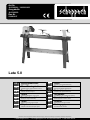 1
1
-
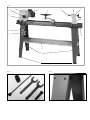 2
2
-
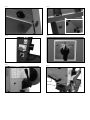 3
3
-
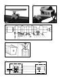 4
4
-
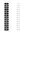 5
5
-
 6
6
-
 7
7
-
 8
8
-
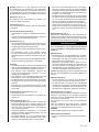 9
9
-
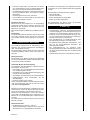 10
10
-
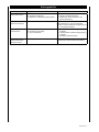 11
11
-
 12
12
-
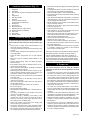 13
13
-
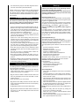 14
14
-
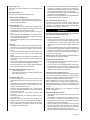 15
15
-
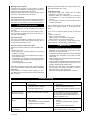 16
16
-
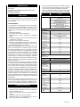 17
17
-
 18
18
-
 19
19
-
 20
20
-
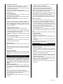 21
21
-
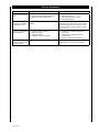 22
22
-
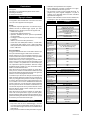 23
23
-
 24
24
-
 25
25
-
 26
26
-
 27
27
-
 28
28
-
 29
29
-
 30
30
-
 31
31
-
 32
32
-
 33
33
-
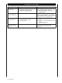 34
34
-
 35
35
-
 36
36
-
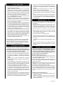 37
37
-
 38
38
-
 39
39
-
 40
40
-
 41
41
-
 42
42
-
 43
43
-
 44
44
-
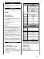 45
45
-
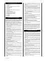 46
46
-
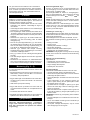 47
47
-
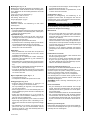 48
48
-
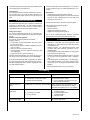 49
49
-
 50
50
-
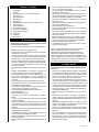 51
51
-
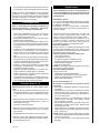 52
52
-
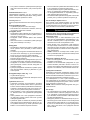 53
53
-
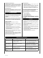 54
54
-
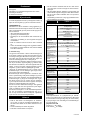 55
55
-
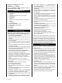 56
56
-
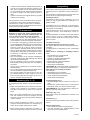 57
57
-
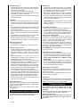 58
58
-
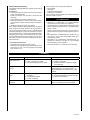 59
59
-
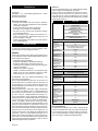 60
60
-
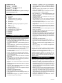 61
61
-
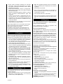 62
62
-
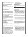 63
63
-
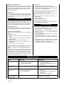 64
64
-
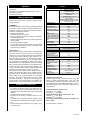 65
65
-
 66
66
-
 67
67
-
 68
68
-
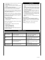 69
69
-
 70
70
-
 71
71
-
 72
72
-
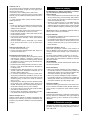 73
73
-
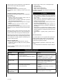 74
74
-
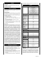 75
75
-
 76
76
-
 77
77
-
 78
78
-
 79
79
-
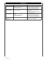 80
80
-
 81
81
-
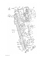 82
82
-
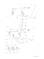 83
83
-
 84
84
-
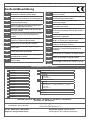 85
85
-
 86
86
-
 87
87
-
 88
88


på andra språk
- italiano: Scheppach Lata 5.0 Manuale utente
- slovenčina: Scheppach Lata 5.0 Používateľská príručka
- português: Scheppach Lata 5.0 Manual do usuário
- français: Scheppach Lata 5.0 Manuel utilisateur
- dansk: Scheppach Lata 5.0 Brugermanual
- Nederlands: Scheppach Lata 5.0 Handleiding


