ABB ACS880-01 Series Quick Installation Manual
- Typ
- Quick Installation Manual

English . . . . . . . . 3
English – USA . . 7
Dansk . . . . . . . . 13
Deutsch . . . . . . 17
Español. . . . . . .23
Suomi . . . . . . . . 29
Français . . . . . . 33
Italiano . . . . . . .39
Nederlands . . . .45
Polski . . . . . . . . 49
Português . . . . . 55
Русский . . . . . . 61
Svenska . . . . . . 67
Türkçe. . . . . . . .71
中文 . . . . . . . . .75
EN
USA
DA
DE
ES
FI
FR
IT
NL
PL
PT
RU
SV
TR
ZH
ABB industrial drives
Quick installation guide
ACS880-01 drives
Frames R1 to R3

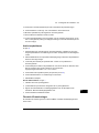
List of related manuals
You can find manuals and other product documents in PDF format on the Internet. See section
Document library on the Internet on the inside of the back cover. For manuals not available in the
Document library, contact your local ABB representative.
The QR code below opens an online listing of the manuals applicable to this product.
ACS880-01 manuals
Drive hardware manuals and guides Code (English)
ACS880-01 hardware manual 3AUA0000078093
ACS880-01 quick installation guide for frames R1 to R3 3AUA0000085966
ACS880-01 quick installation guide for frames R4 and R5 3AUA0000099663
ACS880-01 quick installation guide for frames R6 to R9 3AUA0000099689
ACS880-01 +P940 drives for cabinet installation
supplement
3AUA0000145446
ACS880-01 assembly drawings for cable entry boxes of
IP21 frames R5 to R9
3AUA0000119627
ACS-AP-x assistant control panels user’s manual 3AUA0000085685
Vibration dampers for ACS880-01 drives (frames R4 and
R5, option +C131) installation guide
3AXD50000010497
Vibration dampers for ACS880-01 drives (frames R6 to
R9, option +C131) installation guide
3AXD50000013389
ACS880-01 +C132 marine type-approved drives
supplement
3AXD50000010521
ACS880-01 +N7502 drives for SynRM motors (0.8 to 200
kW) supplement
3AXD50000029482
Drive firmware manuals and guides
ACS880 primary control program firmware manual 3AUA0000085967
Quick start-up guide for ACS880 drives with primary
control program
3AUA0000098062
Option manuals and quides
Manuals and quick guides for I/O extension modules,
fieldbus adapters, etc.
3AUA0000085966 Rev G
MUL
EFFECTIVE: 2017-05-15
2017 ABB Oy. All Rights Reserved.

EN – Quick installation guide 3
EN
DA
DE
ES
FI
FR
IT
NL
PT
RU
SV
TR
CN
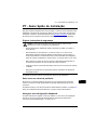
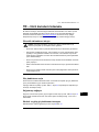
EN – Quick installation guide
This guide instructs briefly how to install the drive. For more detailed instructions,
engineering guide lines, technical data and complete safety instructions, see the
hardware manual (www.abb.com/drives
: Select Document Library and search for
document number 3AUA0000078093 [English]).
Follow the safety instructions
The floor material below the drive must be non-flammable.
Select the power cables
Size the power cables according to local regulations to carry the nominal current
given on the type designation label of your drive.
Typical power cable sizes are listed in table J on page 82. For the conditions of the
sizing, see the hardware manual.
Ensure the cooling
See table B on page 79 for the losses and the cooling air flow through the drive. The
allowed operating temperature range of the drive without derating is -15 to +40 °C.
Protect the drive and input power cable
See table B on page 79. Check that the operating time of the fuse is below 0.5
seconds.
WARNING! Ignoring the following instructions can cause physical injury or
death, or damage to the equipment:
• Only qualified electricians are allowed to install and maintain the drive.
• Never work on the drive, motor cable or motor when main power is applied.
After disconnecting the input power, always wait for 5 min to let the intermediate
circuit capacitors discharge before you start working on the drive, motor or
motor cable.
• Do not work on the control cables when power is applied to the drive or to the
external control circuits.
• Make sure that debris from borings and grindings does not enter the drive when
installing.
• Do not connect the drive to a voltage higher than what is marked on the type
designation label.
3AUA0000085966 Rev G

4 EN – Quick installation guide
EN
DA
DE
ES
FI
FR
IT
NL
PT
RU
SV
TR
CN
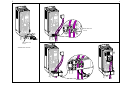
Install the drive on the wall
See figure A on page 79.
Check the insulation of the input and motor cables and the
motor
Check the insulation of the input cable according to local regulations before
connecting it to the drive.
Check the insulation of the motor cable and motor when the cable is disconnected
from the drive, see figure F on page 80. Measure the insulation resistance between
each phase conductor and the Protective Earth conductor using a measuring voltage
of 1000 V DC. The insulation resistance of an ABB motor must exceed 100 Mohm
(reference value at 25 °C or 77 °F). For the insulation resistance of other motors,
please consult the manufacturer’s instructions. Note: Moisture inside the motor
casing will reduce the insulation resistance. If moisture is suspected, dry the motor
and repeat the measurement.
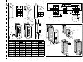
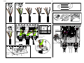
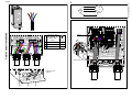
Connect the power cables
See figures C, D, E and G. Use symmetrical shielded cable for motor cabling.
1. Undo the mounting screws at the sides of the front cover.
2. Remove the cover by sliding it forward.
3. Attach the residual voltage warning sticker in the local language to the control
panel mounting platform.
4. Remove the rubber grommets from the lead-through plate for the cables to be
connected.
5. IP21 units
: Fasten the cable connectors (included in the delivery in a plastic bag)
to the cable lead-through plate holes.
6. Prepare the ends of the input power and motor cables as illustrated in the figure.
7. Ground the cable shields 360 degrees in the cable connectors (IP21 units) or
under the clamps (IP55 units).
8. Connect the twisted shield of the input cable to the PE terminal.
9. Connect the PE conductor of the input cable to the additional PE terminal.
10. Connect the twisted shield of the motor cable and resistor cable (if present) to the
grounding terminal.
11. Connect the phase conductors of the input, motor and resistor cables. Tighten the
screws.
12. Install the control cable grounding shelf in the cable entry box.

EN – Quick installation guide 5
EN
DA
DE
ES
FI
FR
IT
NL
PT
RU
SV
TR
CN
13. Secure the cables mechanically outside the drive.
14. Ground the motor cable shield at the motor end. For minimal interference, make a
360-degree grounding at the cable lead-through, or keep the pig tail short.
Connect the control cables
See figure H.
1. Cut adequate holes into the rubber grommets and slide the grommets onto the
cables. Slide the cables through the holes of the bottom plate and attach the
grommets to the holes.
2. Strip the cable ends and cut to suitable length (note the extra length of the
grounding conductors).
3. Ground the outer shields of all control cables 360 degrees at a grounding clamp in
the cable entry box.
4. Ground the pair-cable shields to the grounding clamp. Leave the other end of the
shields unconnected or ground them indirectly via a high-frequency capacitor with
a few nanofarads, eg, 3.3 nF / 630 V.
5. Connect the conductors to the appropriate terminals of the control board (see
page 6).
6. Wire the optional modules if included in the delivery.
7. Reinstall the front cover.
Note for fieldbus cabling. See figure I.
1. Install the additional grounding shelf.
2. Ground the outer shields of the cables 360 degrees at a grounding clamp.
3. Knock out holes in the cable entry box cover for the cables to be installed. Install
the cable entry box cover.
4. Plug the connector to the fieldbus module.
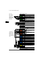
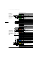
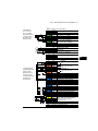
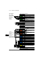
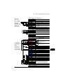
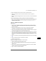
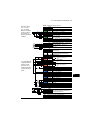
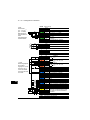
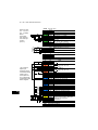
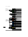
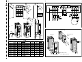
Default I/O connections
The default I/O connections of the Factory macro of the ACS880 primary control
program are shown below.

6 EN – Quick installation guide
EN
DA
DE
ES
FI
FR
IT
NL
PT
RU
SV
TR
CN
XPOW External power input
1 +24VI
24 V DC, 2 A
2 GND
XAI Reference voltage and analog inputs
1 +VREF 10 V DC, R
L
1…10 kohm
2 -VREF -10 V DC, R
L
1…10 kohm
3 AGND Ground
4 AI1+ Speed reference 0(2)…10 V, R
in
>
200 kohm
5 AI1-
6 AI2+ By default not in use. 0(4)…20 mA, R
in
=
100 ohm
7 AI2-
J1 J1 AI1 current/voltage selection jumper
J2 J2 AI2 current/voltage selection jumper
XAO Analog outputs
1 AO1 Motor speed rpm 0…20 mA, R
L
<
500 ohm
2 AGND
3 AO2
Motor current 0…20 mA, R
L
< 500 ohm
4 AGND
XD2D Drive-to-drive link
1 B
Drive-to-drive link
2 A
3 BGND
J3 J3 Drive-to-drive link termination switch
XRO1, XRO2, XRO3 Relay outputs
11 NC
Ready
250 V AC / 30 V DC
2 A
12 COM
13 NO
21 NC
Running
250 V AC / 30 V DC
2 A
22 COM
23 NO
31 NC
Faulted(-1)
250 V AC / 30 V DC
2 A
32 COM
33 NO
XD24 Digital interlock
1 DIIL Run enable
2 +24VD +24 V DC 200 mA
1)
3 DICOM Digital input ground
4 +24VD +24 V DC 200 mA
1)
5 DIOGND Digital input/output ground
J6 Ground selection switch
XDIO Digital input/outputs
1 DIO1 Output: Ready
2 DIO2 Output: Running
XDI Digital inputs
1 DI1 Stop (0) / Start (1)
2 DI2 Forward (0) / Reverse (1)
3 DI3 Reset
4 DI4 Acceleration & deceleration select
5 DI5 Constant speed 1 (1 = On)
6 DI6 By default not in use.
XSTO Safe torque off
1 OUT1
Safe torque off. Both circuits must be
closed for the drive to start.
2 SGND
3 IN1
4 IN2
X12 Safety functions module connection
X13 Control panel connection
X205 Memory unit connection
Wire sizes:
0.5 … 2.5 mm
2
(24…12 AWG)
Tightening
torques: 0.5 N·m
(5 lbf·in) for both
stranded and
solid wiring.
1)
Total load
capacity of these
outputs is 4.8 W
(200 mA / 24 V)
minus the power
taken by DIO1 and
DIO2.
Fault

EN – USA quick installation guide 7
DA
USA
DA
DE
ES
FI
FR
IT
NL
PT
RU
SV
TR
CN
EN – USA quick installation guide
This guide instructs briefly how to install the drive. For more detailed instructions,
engineering guide lines, technical data and complete safety instructions, see the
hardware manual (www.abb.com/drives
: Select Document Library and search for
document number 3AUA0000078093 [English]).
Follow the safety instructions
The floor material below the drive must be non-flammable.
Select the power cables
Select the power cables according to local regulations to carry the nominal current
given on the type designation label of your drive.
Typical power cable sizes are listed in table J on page 82. For the conditions of the
sizing, see the hardware manual.
Ensure the cooling
See table B on page 83 for the losses and the cooling air flow through the drive. The
allowed operating temperature range of the drive without derating is -5 to +104 °F.
Protect the drive and input power cable
See table B on page 83. Check that the operating time of the fuse is below 0.5
seconds.
WARNING! Ignoring the following instructions can cause physical injury or
death, or damage to the equipment:
• Only qualified electricians are allowed to install and maintain the drive.
• Never work on the drive, motor cable or motor when main power is applied.
After disconnecting the input power, always wait for 5 min to let the intermediate
circuit capacitors discharge before you start working on the drive, motor or
motor cable.
• Do not work on the control cables when power is applied to the drive or to the
external control circuits.
• Make sure that debris from borings and grindings does not enter the drive when
installing.
• Do not connect the drive to a voltage higher than what is marked on the type
desgnation label.

8 EN – USA quick installation guide
DA
USA
DA
DE
ES
FI
FR
IT
NL
PT
RU
SV
TR
CN
Install the drive on the wall
See figure A on page 83.
Check the insulation of the input and motor cables and the
motor
Check the insulation of the input cable according to local regulations before
connecting it to the drive.
Check the insulation of the motor cable and motor when the cable is disconnected
from the drive, see figure F on page 84. Measure the insulation resistance between
each phase conductor and the Protective Earth conductor using a measuring voltage
of 1000 V DC. The insulation resistance of an ABB motor must exceed 100 Mohm
(reference value at 25 °C or 77 °F). For the insulation resistance of other motors,
please consult the manufacturer’s instructions. Note: Moisture inside the motor
casing will reduce the insulation resistance. If moisture is suspected, dry the motor
and repeat the measurement.
Connect the power cables
See figures C, D and E on page 83 and 84.
1. Undo the two mounting screws at the sides of the front cover.
2. Remove the cover by sliding it forward.
3. Attach the residual voltage warning sticker in the local language to the control
panel mounting platform.
4. Remove the rubber grommets from the lead-through plate for the cables to be
connected.
5. Fasten the cable conduits to the cable lead-through plate holes. Strip the cable
ends. Slide the cables through the connectors.
6. Connect the grounding conductors to the grounding terminals.
7. Connect the phase conductors of the input and motor cables. Tighten the screws.
8. Units with option +D150:
Connect the brake resistor cable conductors to the R+
and R- terminals.
9. Install the control cable grounding shelf in the cable entry box.
10. Connect the motor cable at the motor end.
Connect the control cables
See figure G on page 84.

EN – USA quick installation guide 9
DA
USA
DA
DE
ES
FI
FR
IT
NL
PT
RU
SV
TR
CN
1. Fasten the cable conduits to the cable lead-through plate holes. Slide the cables
through the connectors.
2. Strip the cable ends and cut to suitable length (note the extra length of the
grounding conductors).
3. Ground the outer shields of all control cables 360 degrees at a grounding clamp in
the cable entry box.
4. Ground the pair-cable shields to the grounding clamp. Leave the other end of the
shields unconnected or ground them indirectly via a high-frequency capacitor with
a few nanofarads, eg, 3.3 nF / 630 V.
5. Connect the conductors to the appropriate terminals of the control board (see
page 10).
6. Wire the optional modules if included in the delivery. For fieldbus cabling, see
page 81.
7. Reinstall the front cover.
Default I/O connections
The default I/O connections of the Factory macro of the ACS880 primary control
program are shown below.

10 EN – USA quick installation guide
DA
USA
DA
DE
ES
FI
FR
IT
NL
PT
RU
SV
TR
CN
XPOW External power input
1 +24VI
24 V DC, 2 A
2 GND
XAI Reference voltage and analog inputs
1 +VREF 10 V DC, R
L
1…10 kohm
2 -VREF -10 V DC, R
L
1…10 kohm
3 AGND Ground
4 AI1+ Speed reference 0(2)…10 V, R
in
>
200 kohm
5 AI1-
6 AI2+ By default not in use. 0(4)…20 mA, R
in
=
100 ohm
7 AI2-
J1 J1 AI1 current/voltage selection jumper
J2 J2 AI2 current/voltage selection jumper
XAO Analog outputs
1 AO1 Motor speed rpm 0…20 mA, R
L
<
500 ohm
2 AGND
3 AO2
Motor current 0…20 mA, R
L
< 500 ohm
4 AGND
XD2D Drive-to-drive link
1 B
Drive-to-drive link
2 A
3 BGND
J3 J3 Drive-to-drive link termination switch
XRO1, XRO2, XRO3 Relay outputs
11 NC
Ready
250 V AC / 30 V DC
2 A
12 COM
13 NO
21 NC
Running
250 V AC / 30 V DC
2 A
22 COM
23 NO
31 NC
Faulted(-1)
250 V AC / 30 V DC
2 A
32 COM
33 NO
XD24 Digital interlock
1 DIIL Run enable
2 +24VD +24 V DC 200 mA
1)
3 DICOM Digital input ground
4 +24VD +24 V DC 200 mA
1)
5 DIOGND Digital input/output ground
J6 Ground selection switch
XDIO Digital input/outputs
1 DIO1 Output: Ready
2 DIO2 Output: Running
XDI Digital inputs
1 DI1 Stop (0) / Start (1)
2 DI2 Forward (0) / Reverse (1)
3 DI3 Reset
4 DI4 Acceleration & deceleration select
5 DI5 Constant speed 1 (1 = On)
6 DI6 By default not in use.
XSTO Safe torque off
1 OUT1
Safe torque off. Both circuits must be
closed for the drive to start.
2 SGND
3 IN1
4 IN2
X12 Safety functions module connection
X13 Control panel connection
X205 Memory unit connection
Wire sizes:
0.5 … 2.5 mm
2
(24…12 AWG)
Tightening
torques: 0.5 N·m
(5 lbf·in) for both
stranded and
solid wiring.
1)
Total load
capacity of these
outputs is 4.8 W
(200 mA / 24 V)
minus the power
taken by DIO1 and
DIO2.
Fault

EN – USA quick installation guide 11
DA
USA
DA
DE
ES
FI
FR
IT
NL
PT
RU
SV
TR
CN
UL checklist
• The drive must be installed in clean air according to enclosure classification.
Cooling air must be clean, free from corrosive materials and electrically
conductive dust. (IP55)- UL Type 12 enclosure. This enclosure provides
protection from airborne dust and light sprays or splashing water from all
directions.
• The maximum ambient air temperature is 40 °C (104 °F) at rated current. The
current is derated for 40 to 55 °C (104 to 131 °F).
• The drive is suitable for use in a circuit capable of delivering not more than
100,000 rms symmetrical amperes, 500 V maximum. The ampere rating is based
on tests done according to UL 508C.
• The cables located within the motor circuit must be rated for at least 75 °C
(167 °F) in UL-compliant installations.
• The input cable must be protected with fuses. Circuit breakers must not be used
without fuses in the USA. Suitable IEC (class aR) fuses and UL (class T) fuses
are listed in the hardware manual. For suitable circuit breakers, contact your local
ABB representative.
• For installation in the United States, branch circuit protection must be provided in
accordance with the National Electrical Code (NEC) and any applicable local
codes. To fulfill this requirement, use the UL classified fuses.
• For installation in Canada, branch circuit protection must be provided in
accordance with the Canadian Electrical Code and any applicable provincial
codes. To fulfill this requirement, use the UL classified fuses.
• The drive provides overload protection in accordance with the National Electrical
Code (NEC).

12 EN – USA quick installation guide
DA
USA
DA
DE
ES
FI
FR
IT
NL
PT
RU
SV
TR
CN

DA – Hurtig installationsvejledning 13
EN
DA
DE
ES
FI
FR
IT
NL
PT
RU
SV
TR
CN
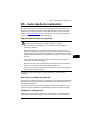
DA – Hurtig installationsvejledning
Denne guide er en kortfattet vejledning i, hvordan man installerer drevet. Hvis du vil
have mere detaljerede instruktioner, tekniske retningslinjer, tekniske data og
komplette sikkerhedsinstruktioner, kan du se hardwaremanualen
(www.abb.com/drives
: Vælg Document Library, og søg efter dokumentnummer
3AUA0000078093 [English].
Følg sikkerhedsinstruktionerne
Gulvmaterialet under drevet skal være ikke-brandbart.
Vælg effektkabler
Vælg en størrelse til kablerne i henhold til lokale forskrifter til at bære den nominelle
strøm, der er anført på mærket med typebetegnelsen på dit drev.
Typiske størrelser på strømkabler vises i tabel J på side 82. Du kan se betingelserne
for størrelsen i hardwaremanualen.
Sørg for kølingen
Se tabel B på side 79 for tabene og drevet gennemstrømning af kølende luft. Drevets
tilladte driftstemperaturområde uden reduktion er -15 til +40 °C.
ADVARSEL! Manglende overholdelse af disse instruktioner kan medføre
fysiske skader eller dødsfald eller skade på udstyret:
• Kun autoriserede elinstallatører må udføre installation og vedligeholdelse af
drevet.
• Undlad at arbejde med drevet, motorkablet eller motoren, når tilslutning til nettet
er foretaget. Vent 5 minutter, efter at netspændingen er frakoblet, så
mellemkredskondensatorerne kan aflades, inden arbejdet med drevet, motoren
eller motorkablet påbegyndes.
• Der må ikke arbejdes med signalkablerne, når netspændingen er tilsluttet
drevet eller de eksterne styrekredse.
• Undgå, at der trænger støv fra boringer og sliberester ind i drevet under
installation.
• Tilslut ikke drevet til en større spænding end den, der er angivet på
typebetegnelsesmærkatet.

14 DA – Hurtig installationsvejledning
EN
EN
DA
DE
ES
FI
FR
IT
NL
PT
RU
SV
TR
CN
Beskyt drevet og netkablet
Se tabel B på side 79. Ud fra sikringens tidsstrømkurve kontrolleres, om driftstiden for
sikringen er under 0,5 sekunder.
Installer drevet på væggen
Se figuren A på side 79.
Kontroller isoleringen på input- og motorkabler samt
motoren
Kontrollér isoleringen af indgangskablet i overensstemmelse med de nationale
forskrifter, inden det tilsluttes drevet.
Kontroller isoleringen af motorkabler og motor, når kablet er koblet fra drevet, se figur
F på side 80. Mål isolationsmodstanden mellem hver faseleder og
beskyttelsesjordlederen med en målespænding på 1000 V DC.
Isolationsmodstanden på en ABB-motor skal være større end 100 Mohm
(referenceværdi ved 25 °C eller 77 °F). Oplysninger om isolationsmodstanden på
andre motorer kan findes i producentens vejledninger. Bemærk! Fugt inden i
motorhuset vil reducere isolationsmodstanden. Hvis der er mistanke om fugt, skal
motoren tørres, og målingen gentages.
Tilslut netkablerne
Se figurerne C, D, E og F. Anvend et skærmet symmetrisk kabel til motorkabling.
1. Løsn monteringsskruerne i siderne af frontdækslet.
2. Fjern dækslet ved at skubbe det fremad.
3. Fastgør advarselsmærkatet om restspænding på det lokale sprog på
betjeningspanelets plade.
4. Fjern gummimufferne fra gennemføringspladen, så kablerne kan tilsluttes.
5. IP21-enheder:
Fastspænd kabelstikkene (inkluderet i leveringen i en plastikpose)
via hullerne i kablets gennemføringsplade.
6. Forbered enderne på nettilslutningen og mototkablerne som vis på følgende figur.
7. Jord kabelskærmene 360 grader i kabelstikkene (IP21-enheder) eller under
bøjlerne (IP55-enheder).
8. Forbind den snoede del af inputkabletskærmen med jordterminalen.
9. Forbind inputkablets PE-leder med den ekstra PE-terminal.
10. Forbind den snoede del af motorkabelskærmen med jordterminalen.
11. Forbind faselederne på indgangs- og motorkablerne. Stram skruerne.

DA – Hurtig installationsvejledning 15
EN
DA
DE
ES
FI
FR
IT
NL
PT
RU
SV
TR
CN
12. Installer styrekablets jordingshylder i kabelindgangens kasse.
13. Fastgør kablerne mekanisk udvendigt på drevet.
14. Tilslut motorkabelskærmen i motorenden. Opnå minimal interferens ved at lave
en 360 graders jording ved kabelgennemføringen eller holde den snoede
kobberskærm kort.
Tilslut styrekablerne
Se figuren H.
1. Klip passende huller i gummimufferne, og skub mufferne på kablerne. Før
kablerne gennem hullerne på bundpladen, og sæt mufferne fast i hullerne.
2. Afisoler kabelenderne, og skær dem af i en passende længde (bemærk
jordledernes ekstra længde).
3. Jord de ydre skærme på alle kabler 360 grader ved en jordingsklemme i
kabelindgangens kasse.
4. Jord skærmene på de parsnoede kabler til jordingsklemmen. Lad den anden
ende af skærmene være utilkoblet, eller slut dem indirekte til jord via en
højfrekvenskondensator på nogle få nanofarad (f.eks. 3,3 nF/630 V).
5. Forbind kablets ledere til de korrekte klemmer på styrekortet (se side 16).
6. Forbind de valgfrie moduler, hvis de indgår i leverancen.
7. Sæt frontdækslet på.
Bemærkning om feltbus-kabelføring. Se figur I.
1. Installer den yderligere forankringshylde.
2. Du skal forankre de yndre afskærmninger på 360 grader ved en jordklemme.
3. Bank huller ud i dækslet på kabelindgangsboksen, hvor kablerne skal monteres.
Monter dækslet på kabelindgangsboksen.
4. Slut stikket til feltbusmodulet.
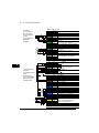
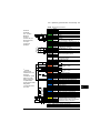
I/O-standardtilslutninger
I/O-standardtilslutninger til fabriksmakroen for det primære styreprogram for ACS880
vises herunder.

16 DA – Hurtig installationsvejledning
EN
EN
DA
DE
ES
FI
FR
IT
NL
PT
RU
SV
TR
CN
XPOW Ekstern indgangseffekt
1 +24VI
24 V DC, 2 A
2 GND
XAI Referencespænding og analoge indgange
1 +VREF 10 V DC, R
L
1…10 kohm
2 -VREF -10 V DC, R
L
1…10 kohm
3 AGND Jord
4 AI1+ Hastighedsreference 0(2)…10 V, R
i
>
200 kohm
5 AI1-
6 AI2+ Som standardindstilling ubenyttet.
0(4)…20 mA, R
i
= 100 ohm
7 AI2-
J1 J1 AI1-jumper til valg af strøm/spænding
J2 J2 AI2-jumper til valg af strøm/spænding
XAO Analoge udgange
1 AO1
Motorhastighed o/min 0…20 mA, R
L
<
500 ohm
2 AGND
3 AO2
motorstrøm 0…20 mA, R
L
< 500 ohm
4 AGND
XD2D Drev til drev-forbindelse
1 B
Drev til drev-forbindelse
2 A
3 BGND
J3 J3 Afbryder til drev til drev-link
XRO1, XRO2, XRO3 Relæudgange
11 NC
Startklar
250 V AC / 30 V DC
2 A
12 COM
13 NO
21 NC
Kører
250 V AC / 30 V DC
2 A
22 COM
23 NO
31 NC
Fejl(-1)
250 V AC / 30 V DC
2 A
32 COM
33 NO
XD24 Digital interlock
1 DIIL Start frigiv
2 +24VD +24 V DC 200 mA
1)
3 DICOM Jording af digital indgang
4 +24VD +24 V DC 200 mA
1)
5 DIOGND Jording af digital indgang/udgang
J6 Afbryder til valg af jord
XDIO Digitale indgange/udgange
1 DIO1 Output: Startklar
2 DIO2 Output: Kører
XDI Digitale indgange
1 DI1 Stop (0) / Start (1)
2 DI2 Forlæns (0) / Baglæns (1)
3 DI3 Reset
4 DI4 Acceleration & deceleration vælg
5 DI5 Konstant hastighed vælg
6 DI6 Som standardindstilling ubenyttet.
XSTO Safe torque off
1 OUT1
Safe torque off. Begge kredse skal være
lukket, for at drevet kan starte.
2 SGND
3 IN1
4 IN2
X12 Modulforbindelse med sikkerhedsfunktioner
X13 Tilslutning til betjeningspanel
X205 Tilslutning til hukommelsesenhed
Ledningsstørrelse:
0,5 … 2,5 mm
2
(24…12 AWG)
Fastspændings-
momenter: 0,5 N·m
(5 lbf·in) til både
trådledere og stive
ledere.
1)
Den totale
belastnings-
kapacitet for disse
udgange er 4,8 W
(200 mA / 24 V)
minus den strøm,
der går til DIO1 og
DIO2.
Fejl

DE – Kurzanleitung für die Installation 17
DE
DA
DE
DE
FI
FR
IT
NL
PT
RU
SV
TR
CN
DE – Kurzanleitung für die Installation
Diese Anleitung beschreibt in Kurzform die Installation des Frequenzumrichters. Eine
detaillierte Beschreibung der Installation, Hinweise für die Planung, die technischen
Daten und die kompletten Sicherheitsvorschriften enthält das Hardware-Handbuch
(www.abb.com/drives
: Wählen Sie Hier finden Sie alle Dokumente zum Download
und suchen Sie das Dokument mit der Nummer 3AUA0000078093 [Englisch]).
Die Sicherheitsanweisungen müssen beachtet werden
Der Boden/das Material unterhalb des Geräts darf nicht entflammbar sein.
Auswahl der Leistungskabel
Die Leistungskabel müssen nach den örtlichen Vorschriften für den auf dem
Typenschild des Frequenzumrichters angegebenen Nennstrom ausreichend
bemessen sein.
Typische Leistungskabelgrößen sind in Tabelle J auf Seite 82 aufgelistet. Die
Bedingungen für die Auswahl der Kabelgrößen enthält das Hardware-Handbuch.
Ausreichende Kühlung sicherstellen
Siehe Tabelle B auf Seite 79, welche Angaben zu den Verlustleistungen und dem
erforderlichen Kühlluftstrom durch den Frequenzumrichter enthält. Der zulässige
WARNUNG! Die Nichtbeachtung der folgenden Vorschriften kann zu
schweren Verletzungen oder tödlichen Unfällen führen:
• Installation und Wartung des Frequenzumrichters dürfen nur von qualifiziertem
Fachpersonal ausgeführt werden.
• Am Frequenzumrichter, dem Motorkabel oder dem Motor dürfen keinerlei
Arbeiten ausgeführt werden, solange die Netzspannung anliegt. Warten Sie
nach dem Abschalten der Spannungsversorgung stets 5 Minuten, bis die
Zwischenkreis-Kondensatoren entladen sind, bevor Sie mit der Arbeit am
Frequenzumrichter, dem Motor oder dem Motorkabel beginnen.
• Führen Sie keine Arbeiten an den Steuerkabeln durch, wenn Spannung am
Frequenzumrichter oder externen Steuerkreisen anliegt.
• Stellen Sie sicher, dass bei der Installation keine Bohrspäne und Staub in den
Frequenzumrichter eindringen.
• Der Frequenzumrichter darf nicht an höhere Spannungen angeschlossen
werden, als die, die auf dem Typenschild angegeben ist.

18 DE – Kurzanleitung für die Installation
DE
DA
DE
DE
FI
FR
IT
NL
PT
RU
SV
TR
CN
Umgebungstemperaturbereich für den Betrieb des Frequenzumrichters ohne
Leistungsminderung beträgt -15 bis +40 °C.
Schutz des Frequenzumrichters und der Einspeisekabel
Siehe Tabelle B auf Seite 79. Prüfen Sie, dass die Ansprechzeit der Sicherungen
weniger als 0,5 Sekunden beträgt.
Wandmontage des Frequenzumrichters
Siehe Abbildung A auf Seite 79.
Prüfung der Isolation der Einspeisekabel sowie des
Motorkabels und des Motors.
Prüfen Sie die Isolation der Einspeisekabel nach den örtlichen Vorschriften vor
Anschluss an den Frequenzumrichter.
Prüfen Sie die Isolation des Motorkabels und des Motors wenn das Motorkabel vom
Frequenzumrichter getrennt ist, sehen Sie Abbildung F auf Seite 80. Messen Sie die
Isolationswiderstände zwischen jeder Phase und dem Schutzleiter (PE) mit einer
Messspannung von 1000 V DC. Der Isolationswiderstand des ABB-Motors muss
mehr als 100 MOhm betragen (Referenzwert bei 25 °C bzw. 77 °F). Die
Isolationswiderstände anderer Motoren entnehmen Sie bitte der Anleitung des
Herstellers.
Hinweis: Feuchtigkeit im Motorgehäuse reduziert den Isolationswiderstand. Bei
Verdacht auf Feuchtigkeit den Motor trocknen und die Messung wiederholen.
Anschluss der Leistungskabel
Siehe Abbildungen C, E, H und F. Verwenden Sie ein symmetrisch geschirmtes
Motorkabel.
1. Lösen Sie die zwei Befestigungsschrauben auf den Seiten der Frontabdeckung.
2. Nehmen Sie die Abdeckung durch Vorziehen ab.
3. Bringen Sie den Restspannungs-Warnaufkleber in der erforderlichen lokalen
Sprache auf dem oberen Teil der Bedienpanel-Halterung an.
4. Nehmen Sie die Gummidichtungen für die anzuschließenden Kabel vom
Durchführungsblech ab.
5. IP21-Einheiten:
Befestigen Sie die Kabelverschraubungen (mitgeliefert, in einem
Kunststoffbeutel) an den Kabeldurchführungen des Kabelanschlussblechs.
6. Vorbereiten Sie die Enden der Einspeisekabel und Motorkabel, wie die Abbildung
zeigt.

DE – Kurzanleitung für die Installation 19
DE
DA
DE
DE
FI
FR
IT
NL
PT
RU
SV
TR
CN
7. Erden Sie die Kabelschirme in den Kabelverschraubungen (IP21-Einheiten) oder
unter den Kabelschellen (IP55-Einheiten) 360-Grad.
8. Schließen Sie den verdrillten Schirm des Eingangskabels an die Erdungsklemme
an
9. Schließen Sie den PE-Leiter des Eingangskabels an die zusätzliche PE-Klemme
an.
10. Schließen Sie den verdrillten Schirm des Motorkabels an die Erdungsklemme an.
11. Schließen Sie die Phasenleiter der Einspeise- und Motorkabel an. Ziehen Sie die
Schrauben der Anschlüsse fest.
12. Installieren Sie die Steuerkabel-Erdungsschellenschiene im
Kabelanschlusskasten.
13. Sichern Sie die Kabel mechanisch außerhalb des Frequenzumrichters.
14. Schließen Sie die Motorkabelschirme motorseitig an Erde/PE an. Stellen Sie zur
Minimierung von Hochfrequenzstörungen eine 360-Grad-Erdung an den
Kabeldurchführungen her oder halten Sie die verdrillten Schirme möglichst kurz.
Anschluss der Steuerkabel
Siehe Abbildung H.
1. Schneiden Sie eine passende Öffnung in die Gummidurchführungsdichtungen
und schieben Sie die Dichtungen auf die Kabel. Stecken Sie Die Kabel durch die
Öffnungen des unteren Abschlussblechs und drücken Sie die Dichtungen in die
Öffnungen.
2. Schneiden Sie die Kabel auf die passende Länge ab (die erforderliche Länge der
Erdleiter berücksichtigen) und abisolieren Sie die Leiterenden.
3. Stellen Sie eine 360-Grad-Erdung an einer Erdungsklemme für die äußeren
Schirme aller Steuerkabel im Kabelanschlusskasten her.
4. Schließen Sie die Schirme der zweiadrigen Steuerkabel an die Erdungsklemme
an. Schließen Sie das andere Ende der Schirme nicht an oder erden Sie es
indirekt über einen Hochfrequenz-Kondensator mit wenigen Nanofarad (z.B. 3,3
nF / 630 V).
5. Schließen Sie die Kabel an die entsprechenden Klemmen der Regelungseinheit
an (siehe Seite 21).
6. Schließen Sie die optionalen Module, falls mitgeliefert, an.
7. Montieren Sie die Frontabdeckung wieder.
Hinweis zur Feldbus-Verkabelung. Siehe Abbildung I.
1. Installieren Sie das zusätzliche Erdungs-/Abfangblech.

20 DE – Kurzanleitung für die Installation
DE
DA
DE
DE
FI
FR
IT
NL
PT
RU
SV
TR
CN
2. Erden Sie die äußeren Kabelschirme 360 Grad an einer Erdungsklemme.
3. Brechen Sie Einführungsöffnungen für die zu installierenden Kabel in die
Abdeckung des Kabeleinführungskastens. Montieren Sie die Abdeckung des
Kabeleinführungskastens wieder.
4. Stecken Sie den Stecker in das Feldbusadaptermodul.
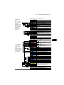
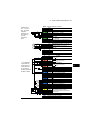
Standard E/A-Anschlüsse
Die Standard-E/A-Anschlüsse des Makros Werkseinstellung des ACS880 Haupt-
Regelungsprogramms sind unten dargestellt.
Sidan laddas...
Sidan laddas...
Sidan laddas...
Sidan laddas...
Sidan laddas...
Sidan laddas...
Sidan laddas...
Sidan laddas...
Sidan laddas...
Sidan laddas...
Sidan laddas...
Sidan laddas...
Sidan laddas...
Sidan laddas...
Sidan laddas...
Sidan laddas...
Sidan laddas...
Sidan laddas...
Sidan laddas...
Sidan laddas...
Sidan laddas...
Sidan laddas...
Sidan laddas...
Sidan laddas...
Sidan laddas...
Sidan laddas...
Sidan laddas...
Sidan laddas...
Sidan laddas...
Sidan laddas...
Sidan laddas...
Sidan laddas...
Sidan laddas...
Sidan laddas...
Sidan laddas...
Sidan laddas...
Sidan laddas...
Sidan laddas...
Sidan laddas...
Sidan laddas...
Sidan laddas...
Sidan laddas...
Sidan laddas...
Sidan laddas...
Sidan laddas...
Sidan laddas...
Sidan laddas...
Sidan laddas...
Sidan laddas...
Sidan laddas...
Sidan laddas...
Sidan laddas...
Sidan laddas...
Sidan laddas...
Sidan laddas...
Sidan laddas...
Sidan laddas...
Sidan laddas...
Sidan laddas...
Sidan laddas...
Sidan laddas...
Sidan laddas...
Sidan laddas...
Sidan laddas...
Sidan laddas...
Sidan laddas...
-
 1
1
-
 2
2
-
 3
3
-
 4
4
-
 5
5
-
 6
6
-
 7
7
-
 8
8
-
 9
9
-
 10
10
-
 11
11
-
 12
12
-
 13
13
-
 14
14
-
 15
15
-
 16
16
-
 17
17
-
 18
18
-
 19
19
-
 20
20
-
 21
21
-
 22
22
-
 23
23
-
 24
24
-
 25
25
-
 26
26
-
 27
27
-
 28
28
-
 29
29
-
 30
30
-
 31
31
-
 32
32
-
 33
33
-
 34
34
-
 35
35
-
 36
36
-
 37
37
-
 38
38
-
 39
39
-
 40
40
-
 41
41
-
 42
42
-
 43
43
-
 44
44
-
 45
45
-
 46
46
-
 47
47
-
 48
48
-
 49
49
-
 50
50
-
 51
51
-
 52
52
-
 53
53
-
 54
54
-
 55
55
-
 56
56
-
 57
57
-
 58
58
-
 59
59
-
 60
60
-
 61
61
-
 62
62
-
 63
63
-
 64
64
-
 65
65
-
 66
66
-
 67
67
-
 68
68
-
 69
69
-
 70
70
-
 71
71
-
 72
72
-
 73
73
-
 74
74
-
 75
75
-
 76
76
-
 77
77
-
 78
78
-
 79
79
-
 80
80
-
 81
81
-
 82
82
-
 83
83
-
 84
84
-
 85
85
-
 86
86


ABB ACS880-01 Series Quick Installation Manual
- Typ
- Quick Installation Manual
på andra språk
- italiano: ABB ACS880-01 Series
- español: ABB ACS880-01 Series
- Deutsch: ABB ACS880-01 Series
- polski: ABB ACS880-01 Series
- português: ABB ACS880-01 Series
- français: ABB ACS880-01 Series
- Türkçe: ABB ACS880-01 Series
- English: ABB ACS880-01 Series
- dansk: ABB ACS880-01 Series
- русский: ABB ACS880-01 Series
- suomi: ABB ACS880-01 Series
- Nederlands: ABB ACS880-01 Series
Relaterade papper
-
ABB ACS880-01-035A-7 Quick Installation Manual
-
-
-
-
ABB ACSM1-04 Series Quick Installation Manual
-
ABB ACS850-04 series Quick Installation Manual
-
-
-
-