Simplicity 405627X51A Användarmanual
- Kategori
- Gräsklippare
- Typ
- Användarmanual
Denna manual är också lämplig för

Instruction Book - Riding Mower Model 405627x51A
Manuel de l’utilisateur -
Tondeuse autoportée modèle 405627x51A
Betriebsanleitung - Aufsitzmäher Modell 405627x51A
Istruzioni per l’uso - Trattore tagliaerba Modello 405627x51A
Gebruikshandleiding - Zitmaaier model 405627x51A
Driftsvejledning - Plænetraktor Model 405627x51A
Bruksanvisning - Rider modell 405627x51A
Användarhandbok - Trädgårdtraktor modell 405627x51A
Käyttöohjeet - Ajettava ruohonleikkuri, malli 405627x51A
Manual de instrucciones - Cortacésped autoportado Modelo 405627x51A
Juhend - Traktorniiduki mudel 405627x51A
Åã÷åéñßäéï ïäçãéþí ÷ñÞóçò -
ÌïíôÝëï ÷ïñôïêïðôéêïý ãéá åðï÷ïýìåíï ÷åéñéóôÞ 405627x51A
Használati Útmutató - Önjáró fûnyíró gép 405627x51A modell
Instrukciju grāmata - Braucošs pļāvēja modelis 405627x51A
Instrukcija - Sėdimoji žoliapjovė modelis 405627x51A
Instrukcja - Kosiarka z siedziskiem model 405627x51A
Návod k použití - Traktorová sekaèka, model 405627x51A
F
D
I
NL
DK
N
S
SF
GB
E
EE
GR
H
LV
LT
PL
1740490 TP 199--4459--00--RD--R
CZ

2
1740490
1
1
2
3
4 (17x192)
6
7 (17x195)
5 (30x49)
2
1
2
3
4 (17x47)
5 (1001054)
1
2
3
7
6 (17x146)
4 (25x3)
3
5
1
3
4
2
6
8
6 (2x82)
7 (14x79)
4
3
1
2
4
5
7
5
1
2
6
1
2
3
4
5
6
7
7
1
8
2
6
1
2
3
4
5
9
4
5
4
6
1
2
3
7
10
11
12
1
10
11
6
5
4
12
1
2
13
3
1
2
14 15

3
1740490
2
1
6
5
7
5
9
7
4
5
8
13
16
3
2
1
17
1
2
5
18
432
1
19
4
2
1,3
1,2
20
7
1
2
6
3
4
1/4” (6mm)
7
3
21
1
2
3
3
4
4
5
6
7
8
9
22

4
1740490
12 3
4
5
6
7
9
23
8
10
MAX 90N
+
MAX 150N
+
11 12
13
14
1
2
3
4
5
67
8
9
10 11 12
13
14
15
24
1001054
2x82
14x79
17x47
20729
30x49
17x195
17x192
17x146
25x3
25

GB
5
1740490
CONTENTS
INTERNATIONAL PICTORIALS 5
LIMITED WARRANTY 6
OWNER’S INFORMATION 7
SAFE OPERATION PRACTICES 7
ASSEMBLY 8
OPERATION 9
MAINTENANCE CHART 11
MAINTENANCE 11
TROUBLE SHOOTING CHART 14
INTERNATIONAL PICTORIALS
IMPORTANT: The following pictorials are lo-
cated on your unit or on literature supplied
with the product. Before you operate the
unit, learn and understand the purpose for
each pictorial.
NOTE: Illustrations and pictorials begin
on page 2.
Safety Warning Pictorials (Figure 23)
1 WARNING
2 IMPORTANT: Read Owner’s Manual
Before Operating This Machine.
3 WARNING: Thrown Objects. Keep
Bystanders Away. Read User Instructions
Before Operating This Machine.
4 WARNING: Do Not Use This Machine On
Slopes Greater Than 10 Degrees.
5 DANGER: Keep People, Especially
Children, Away From Unit.
6 DANGER: No Step.
7 DANGER: Keep Feet And Hands Away
From Rotating Blade.
8 Declared airborne sound power level of 100
dB(A) is in accordance with Directive
2000/14/EC.
9 DANGER: Disconnect Spark Plug Wire
Before Servicing Unit.
10 WARNING: Hot Surface.
11 WARNING: Use Caution When Connecting
Or Disconnecting Accessories.
12 WARNING: Crushed Fingers.
13 IMPORTANT: Follow Instructions In
Owner’s Manual To Level The Deck.
14 WARNING: Stay Clear Of Mower Blade As
Long As Engine Is Running.
Control And Operating Pictorials
(Figure 24)
1 Engine Start
2 Lights
3 Engine Run
4 Engine Stop
5 Engine Run
6 Brake
7 Parking Brake
8 Clutch
9 Slow
10 Fast
11 Choke
12 Oil
13 Blade Rotation Control
14 Raise
15 Fuel
Declared vibration emission values in accordance with Directive 98/37/EC.
Vibration Emission according to BS EN 1032: Seat 2
m/s
2
,
Right Running Board 2,9 m/s
2
, Left Running Board 3,3 m/s
2
Vibration Emission according to BS EN 1033: Steering Wheel 3,5 m/s
2
Values determined with operator in operating position when the machine was
operated stationary on a concrete surface at 2850 min--1.
MODEL NO.: 405627x51A
SERIAL NO.:
2850 min-1
165 kg
SKU No.:
YYYY MM DD:
2006.12.13
www.briggsandstratton.com
Declared airborne sound power level of 100 dB(A) is in accordance with Directive
2000/14/EC.
Sound Pressure Level at operator position 83 dB.
Values determined at ear according to the specifications of EN 836/A2:2001.
Net kW 6.39
Assembled in Lawrenceburg, TN 38464; USA
by Swisher, Inc. for Briggs & Stratton Corporation

GB
6
1740490
BRIGGS & STRATTON CORPORATION OWNER WARRANTY POLICY
Effective January 1, 2006 replaces all undated Warranties and all Warranties dated before January 1, 2006
Briggs & Stratton Corporation will repair or replace, free of charge, any part(s) of the product that is defective in material or workmanship or both.
Transportation charges on product submitted for repair or replacement under this warranty must be borne by purchaser. This warranty is effective
for the time periods and subject to the conditions stated below. For warranty service, find the nearest Authorized Service Dealer in your area. For
warranty service, find the nearest Authorized Service Dealer in our dealer locator map at www.murray.com.
THERE IS NO OTHER EXPRESS WARRANTY. IMPLIED WARRANTIES, INCLUDING THOSE OF MERCHANTABILITY AND FITNESS FOR A
PARTICULAR PURPOSE, ARE LIMITED TO ONE YEAR FROM PURCHASE, OR TO THE EXTENT PERMITTED BY LAW ANY AND ALL
IMPLIED WARRANTIES ARE EXCLUDED. LIABILITY FOR INCIDENTAL OR CONSEQUENTIAL DAMAGES ARE EXCLUDED TO THE
EXTENT EXCLUSION IS PERMITTED BY LAW. Some states or countries do not allow limitations on how long an implied warranty lasts, and
some states or countries do not allow the exclusion or limitation of incidental or consequential damages, so the above limitation and exclusion
may not apply to you. This warranty gives you specific legal rights and you may also have other rights which vary from state to state or country to
country.
LIMITED WARRANTY
WARRANTY TERMS
Consumer Commercial Condition of
Brand / Unit Use Use Warranty Term
Riders / Tractors 2 years 90 days..................... ...........
The warranty period begins on the date of purchase by the first retail consumer or commercial end user, and continues for the period of
time stated in the table above. “Consumer use” means personal residential household use by a retail consumer. “Commercial use” means
all other uses, including use for commercial, income producing or rental purposes. Once product has experienced commercial use, it shall
thereafter be considered as commercial use for purposes of this warranty.
No warranty registration is necessary to obtain warranty on Murray branded products. Save your proof of purchase receipt. If you do not
provide proof of the initial purchase date at the time warranty service is requested, the manufacturing date of the product will be used to
determine the warranty.
ABOUT YOUR WARRANTY
We welcome warranty repair and apologize to you for being inconvenienced. Any Authorized Service Dealer may perform warranty
repairs. Most warranty repairs are handled routinely, but sometimes requests for warranty service may not be appropriate. For example,
warranty service would not apply to the product if damage occurred because of misuse, lack of routine maintenance, shipping, handling,
warehousing or improper installation. Similarly, the warranty is void if the serial number on the product has been removed or the product
has been altered or modified.
This warranty covers product related defective material and/or workmanship only. To avoid misunderstanding which might occur be-
tween the customer and the Dealer, listed below are some of the causes of product failure that the warranty does not cover.
• Normal Wear: Small Engine Powered Equipment, like all mechanical devices, needs periodic parts and service to perform well. Warranty does not
cover repair when normal use has exhausted the life of the product or part.
• Installation: This warranty does not apply to product that has been subjected to improper or unauthorized installation, alteration or modification. Nor
installations that prevent starting, cause unsatisfactory engine performance.
• Improper Maintenance: The life of this product depends upon the conditions under which it operates, and the care it receives. Recommended
maintenance and adjustment intervals are stated in the Operator’s Manual. Often product, such as tillers, edgers, rotary mowers, are used in dusty
or dirty conditions, which can cause what appears to be premature wear. Such wear, when caused by dirt, dust, or other abrasive material entering
the product because of improper maintenance is not covered by warranty. The warranty will not cover repairs due to problems caused by replace-
ment parts that are not original manufactured part(s).
• Incorrect and/or insufficient fuel or lubrication: This warranty does not cover damage caused by the use of stale fuel, or altered gasolines. Dam-
age to engine or engine components ie, combustion chamber, valves, valve seats, valve guides, burned starter motor windings caused by use of
alternate fuels such as liquified petroleum, natural gas, are not covered unless engine is certified for this operation. Parts which are scored or bro-
ken because product was operated with insufficient, contaminated or incorrect grade of lubricating oil as well as product components damaged due
to lack of lubrication are not covered.
• Operational Misuse: Proper operation of the product is stated in the Operator’s Manual. Product damaged by overspeeding, overheating, or opera-
tion in a confined area without sufficient ventilation. Product broken by excessive vibration caused by a loose engine mounting, loose or unbalanced
blades, impellers, overspeeding, or bent crankshaft due to striking of solid object. Damage or malfunctions resulting from accidents, abuse, or im-
proper servicing or freezing or chemical deterioration, as well as operating in excess of recommended capacities as outlined in the Operator’s
Manual are not covered.
• Routine tune-up, wear items or adjustments: This warranty excludes wear items such as oil, belts, blades, o-rings, filters, etc.
• Other exclusions: Repair or adjustments for part(s) that are not manufactured by Briggs & Stratton Corporation, are not covered, see warranty for
respective manufacturers. This warranty excludes failures due to acts of God and other force majeure events beyond the manufacturers con-
trol. Also excluded are used, reconditioned, and demonstration products.
Warranty service is available only through Authorized Service Dealers. Locate your nearest dealer in our locator map at www.murray.com.

GB
7
1740490
OWNER’S INFORMATION
Know your product: If you understand the unit
and how the unit operates, you will get the best
performance. As you read this manual, compare
the illustrations to the unit. Learn the location
and the function of the controls. To help prevent
an accident, follow the operating instructions
and the safety rules. Keep this manual for future
reference.
WARNING: Look for this symbol to indicate
important safety precautions. This symbol
indicates: “Attention! Become Alert! Your
Safety Is At Risk.”
Responsibility Of The Owner
WARNING: This cutting machine is
capable of amputating hands and
feet and throwing objects. Failure
to observe the following safety instructions
could result in serious injury or death to
the operator or bystanders.
The responsibility of the owner is to
follow the instructions below.
SAFE OPERATION PRACTICES
For Ride--On (Riding)
Rotary Mower Machines
Training
1. Read the instructions carefully. Be familiar
with the controls and the proper use of the
equipment.
2. Never allow children or people unfamiliar
with these instructions to use the mower.
Local regulations may restrict the age of
the operator.
3. Never mow while people, especially
children, or pets are nearby.
4. Keep in mind that the operator or user is
responsible for accidents or hazards occur-
ring to other people or their property.
5. Do not carry passengers.
6. All drivers should seek and obtain pro-
fessional and practical instruction. Such
instruction should emphasize:
a. the need for care and concentration
when working with ride--on machines;
b. control of a ride--on machine sliding
on a slope will not be regained by the
application of the brake. The main
reasons for loss of control are:
• insufficient wheel grip;
• being driven too fast;
• inadequate braking
• the type of machine is unsuitable
for its task;
• lack of awareness of the effect of
ground conditions, especially
slopes;
• incorrect hitching and load dis-
tribution.
Preparation
1. While mowing, always wear substantial
footwear and long trousers. Do not operate
the equipment when barefoot or wearing
open sandals.
2. Thoroughly inspect the area where the
equipment is to be used and remove all ob-
jects which may be thrown by the machine.
3. WARNING -- Petrol is highly flammable.
a. Store fuel in containers specifically de-
signed for this purpose.
b. Refuel outdoors only and do not
smoke while refuelling.
c. Add fuel before starting the engine.
Never remove the cap of the fuel tank
or add petrol while the engine is run-
ning or when the engine is hot.
d. If petrol is spilled, do not attempt to
start the engine but move the machine
away from the area of spillage and
avoid creating any source of ignition
until petrol vapours have dissipated.
e. Replace all fuel tanks and container
caps securely.
4. Replace faulty silencers.
5. Before using, always visually inspect to see
that the blades, blade bolts and cutter as-
sembly are not worn or damaged. Replace
worn or damaged blades and bolts in sets
to preserve balance.
6. On multi--blade machines, take care as ro-
tating one blade can cause other blades to
rotate.
Operation
1. Do not operate the engine in a confined
space where dangerous carbon monoxide
fumes can collect.
2. Mow only in daylight or in good artificial
light.
3. Before attempting to start the engine, dis-
engage all blade attachment clutches and
shift into neutral.
4. Do not use on slopes of more than 10 de-
grees.
5. Remember there is no such thing as a
“safe” slope. Travel on grass slopes re-
quires particular care. To guard against
overturning:
a. do not stop or start suddenly when
going up or downhill;
b. engage clutch slowly, always keep
machine in gear, especially when tra-
velling downhill;
c. machine speeds should be kept low
on slopes and during tight turns;
d. stay alert for humps and hollows and
other hidden hazards;
e. never mow across the face of the
slope, unless the mower is designed
for this purpose.
6. Use care when pulling loads or using heavy
equipment.
a. Use only approved drawbar hitch
points.
b. Limit loads to those you can safely
control.
c. Do not turn sharply. Use care when
reversing.
d. Use counterweight(s) or wheel
weights when suggested in the In-
struction Book.
7. Watch out for traffic when crossing or near
roadways.
8. Stop the blades rotating before crossing
surfaces other than grass.
9. When using any attachments, never direct
discharge of material toward bystanders
nor allow anyone near the machine while in
operation.
10. Never operate the mower with defective
guards or shields, or without safety protec-
tive devices in place.
11. Do not change the engine governor set-
tings or overspeed the engine. Operating
an engine at excessive speed may in-
crease the hazard of personal injury.
12. Before leaving the operator’s position
a. disengage the power take--off and
lower the attachments;
b. change into neutral and set the park-
ing brake;
c. stop the engine and remove the key.
13. Disengage drive to attachments, stop the
engine, and disconnect the spark plug
wire(s) or remove the ignition key
a. before cleaning blockages or unclog-
ging chute;
b. before checking, cleaning or working
on the mower;
c. after striking a foreign object. Inspect
the mower for damage and make re-
pairs before restarting and operating
the equipment;
d. if the machine starts to vibrate abnor-
mally (check immediately).
14. Disengage drive to attachments when
transporting or not in use.
15. Stop the engine and disengage drive to at-
tachment
a. before refuelling;
b. before removing the grass catcher;
c. before making height adjustment un-
less adjustment can be made from the
operator’s position.
16. Reduce the throttle setting during engine
run--out and, if the engine is provided with a
shut--off valve, turn the fuel off at the con-
clusion of mowing.
17. Before and when backing, look behind and
down for small children.
18. Use extra care when approaching blind
corners, shrubs, trees or other objects that
may obscure vision.
Maintenance and Storage
1. On multi--blade machines, take care as ro-
tating one blade can cause other blades to
rotate.
2. When machine is to be parked, stored or
left unattended, lower the cutting means
unless a positive mechanical lock is used.
3. Keep all nuts, bolts, and screws tight to be
sure the equipment is in safe working
condition.
4. Never store the equipment with petrol in the
tank inside a building where fumes may
reach an open flame or spark.
5. Allow the engine to cool before storing in
any enclosure.
6. To reduce the fire hazard, keep the engine,
silencer, battery compartment and petrol
storage area free of grass, leaves, or ex-
cessive grease.
7. Check the grass catcher frequently for
wear or deterioration.
8. Replace worn or damaged parts for safety.
9. If the fuel tank has to be drained, this
should be done outdoors.

GB
8
1740490
ASSEMBLY
All fasteners are in the parts bag. Do not discard
any parts or material until the unit is assembled.
WARNING: Before doing any as-
sembly or maintenance to the
mower, remove the wire from the
spark plug.
NOTE: In this instruction book, left and right
describe the location of a part with the oper-
ator on the seat.
NOTE: Illustrations and pictorials begin on
page 2.
NOTE: To assemble the following loose
parts, use the fasteners shown at full size in
Figure 25.
How To Install The Front Wheels
(Figure 1)
Use a knife and cut the four sides of the con-
tainer. Install the front wheels (1) in the con-
tainer.
NOTE: Use a piece of wood about 4 feet (1.25
meters) long to raise the front of the tractor.
If a piece of wood cannot be found, get
another person to help lift the tractor. Be
careful, do not let the tractor fall.
1. Raise the front of the tractor. Set a support
(block of wood) under the tractor.
2. Make sure the valve stem (2) is to the out-
side of the tractor. Slide the front wheel (1)
on the spindle (3).
3. Fasten each front wheel (1) with washer (4)
and cotter pin (5). Bend the ends of the
cotter pin (5) appart to keep the front wheel
(1) on the spindle (3).
4. After the front wheels (1) are installed, lift
the tractor from the support. Roll the tractor
off of the container.
5. If your tractor has hub caps (6), install the
hub caps (6). Make sure the washers (4)
hold the hub caps (6) in place.
How To Install The Seat (Figure 2)
1. Carefully remove the plastic bag from the
seat (1).
2. Align the holes in the seat hinge (2) to the
holes in the seat (1). Fasten the seat (1) to
the seat hinge (2) with the fasteners (4) and
(5).
3. Check the operating position of the seat (1).
If the seat (1) needs to be adjusted, loosen
the two wing bolts (5). Slide the seat (1) for-
ward or backward along the seat adjusting
holes (3). Tighten the wing bolts (5).
How To Assemble The Steering Wheel
(Figure 3)
1. Make sure the front wheels point forward.
2. Slide the cover (3) over the steering post
(2). Make sure the collar of the cover (3) is
on top.
3. Slide the steering wheel (1) onto the steer-
ing post (2).
4. Attach the steering wheel (1) to the steer-
ing post (2) with screw (4) and washer (6).
5. Some models have an optional insert (7) in
the parts bag. Attach the insert (7) to the
centre of the steering wheel (1).
Maintenance Free Battery (Figure 4)
IMPORTANT: Before you attach the battery
cables to the battery, check the battery date.
The battery date tells if the battery must be
charged.
1. Check the top and the side of the battery (1)
for the location of the battery date.
2. If the battery (1) is put into service before
the , the battery cables can be attached with-
out charging the battery (1). See “How To
Install The Battery Cables”.
3. If the battery (1) is put into service after the ,
the battery (1) must be charged. See “How
To Charge The Maintenance Free Battery”.
How To Charge The Battery (Figure 4)
WARNING: When you charge the
battery, do not smoke. Keep the bat-
tery away from any sparks. The
fumes from the battery acid can cause an
explosion.
1. Remove the battery (1) and battery tray (3).
2. Remove the protective cap from the battery
terminal.
3. Use a 12 volt battery charger to charge the
battery (1). Charge at a rate of 6 amperes
for one hour. If you do not have a battery
charger, have an authorized service centre
charge the battery.
4. Install the battery (1) and battery tray (3).
Make sure the positive (+) terminal (4) is on
the left side.
How To Install The Battery Cables
(Figure 4)
WARNING: To prevent sparks, fasten
the red cable to the positive (+) ter-
minal before you connect the black
cable.
1. Remove the protective cap from the battery
terminal.
2. Slide the terminal cover (2) onto the red
cable (5). Fasten the red cable (5) to the
positive (+) terminal (4) with the fasteners
(6) and (7).
3. Fasten the black cable 8 to the negative (--)
terminal with the fasteners (6) and (7).
Check The Tyres
Check the air pressure in the tyres. Tyres with
too much air pressure will cause the unit to ride
rough. Also, the wrong air pressure will keep the
mower housing from cutting level. The correct
air pressure is: Front Tyres 0,97 BAR (14 PSI),
Rear Tyres 0,69 BAR (10 PSI). The tyres were
over inflated for shipment.
Check The Level Of The Mower
Housing
Make sure the level of cut is still correct. After
you mow a short distance, look at the area that
was cut. If the mower housing does not cut level,
see the instructions on “How To Level The
Mower Housing” in the Maintenance section of
this instruction book.
How To Prepare The Engine
NOTE: The engine was shipped from the fac-
tory filled with oil. Check the level of the oil.
Add oil as needed.
See the engine manufacturer’s instructions for
the type of petrol and oil to use. Before you use
the unit, read the information on safety, oper-
ation, maintenance, and storage.
WARNING: Follow the engine manu-
facturer’s instructions for the type o
f
petrol and oil to use. Always use a
safety petrol container. Do not smoke when
adding petrol to the engine. When inside an
enclosure, do not fill with petrol. Before you
add petrol, stop the engine. Let the engine
cool for several minutes.
Important! Before You Start Mowing
U Check the engine oil.
U Fill the fuel tank with petrol.
U Check the air pressure of the tyres.
U Check the level of the mower hous-
ing.
U Attach the battery cables.

GB
9
1740490
OPERATION
NOTE: Illustrations and pictorials begin on
page 2.
Location Of Controls
(Figure 5, Figure 20 )
Blade Rotation Control (1): Use the blade rota-
tion control to start and stop the rotation of the
blade.
Brake Pedal (2): Use the brake pedal to quickly
stop.
Headlight Switch (3): The headlight switch is
the first part of the ignition switch. To use the
lights with the engine running, turn the key to the
position for the lights.
Ignition Switch (3): Use the ignition switch to
start and stop the engine.
Speed Control Pedal (4): Use the speed con-
trol pedal to change the speed and the direction
of the unit.
Lift Lever (5): Use the lift lever to change the
height of cut.
Parking Brake Lever (6): Use the parking brake
lever to engage the brake when you leave the
unit.
Throttle Control Lever (7): Use the throttle
control lever to increase or decrease the speed
of the engine.
(Figure 20) Automatic Drive disconnect (1):
use the automatic drive disconnect, located
under the seat, to disengage the transmission.
Attachments
This unit can use many different attachments.
This unit can pull attachments like a lawn
sweeper, a lawn aerator, or a hopper spreader.
This unit can not use attachments that engage
the ground like a plough, a disk harrow, or a
cultivator.
For trailer and pull--behind attachments, the
maximum weight is 113 kg (250 lbs.).
How To Use The Throttle Control
(Figure 5)
Use the throttle control (7) to increase or de-
crease the speed of the engine.
1. The FAST position is marked with a detent.
For normal operation and when using a
grass bagger, move the throttle control to the
FAST position. For maximum charging of the
battery and for a cooler running engine, oper-
ate the engine in the FAST position.
2. The engine governor is set at the factory for
maximum performance. Do not adjust the
governor to increase the speed of the en-
gine.
How To Use The Blade Rotation Control
(Figure 5)
Use the blade rotation control (1) to engage
the blade(s).
1. Before you start the engine, make sure the
blade rotation control (1) is in the DISEN-
GAGE position.
2. Move the blade rotation control (1) to the
ENGAGE position to rotate the blade(s).
NOTE: If the engine stops when you en-
gage the blade(s), the seat switch is not
activated. Make sure you sit in the middle
of the seat.
3. Move the blade rotation control (1) to the
DISENGAGE position to stop the blade(s).
Before you leave the operator’s position,
make sure the blade(s) has stopped rotating.
4. Before you ride the unit across a sidewalk or
a road, move the blade rotation control (1)
to the DISENGAGE position.
WARNING: Always keep your
hands and feet away from the
blade, deflector opening, and the
mower housing when the engine runs.
How To Use The Speed Control Pedal
(Figure 5)
The drive system uses a Hydrostatic Automatic
Drive transmission. The Hydrostatic trans-
mission is very easy to operate. This type of
drive system does not require a shift lever or a
clutch pedal.
The speed and direction of travel is controlled by
a single speed control pedal (4) operated with
your right foot. Do not use the left brake pedal in
normal operation. Only use the left brake pedal
to quickly stop in an emergency.
How To Drive Forward
1. (Figure 20) The automatic drive discon-
nect (1) must be in the DRIVE position (2).
2. Slowly release your left foot from the brake
pedal.
3. Move the throttle control to the FAST posi-
tion.
4. (Figure 19) Slowly push the speed control
pedal (1) forward (4) to the desired speed.
5. To increase forward speed, slowly move the
speed control pedal (1) forward. To reduce
forward speed, slowly release the speed
control pedal (1) until the unit slows to the
desired speed.
How To Drive In Reverse
1. Look to the rear.
2. Slowly push the speed control pedal (1) to
the REVERSE position (2).
How To Change Directions
CAUTION: To change directions, do not use
the left brake pedal. Use only the speed con-
trol pedal.
1. Slowly remove your foot from the speed
control pedal (1).Thespeed control pedal
(1) will automatically return to the NEUTRAL
position (3).
2. When the unit stops, slowly move the speed
control pedal (1) to the desired direction.
How To Disconnect The Transmission
(Figure 20)
To push the unit, use the automatic drive dis-
connect (1) to release the transmission. The
automatic drive disconnect (1) is under the
seat.
1. The engine must be off.
2. Raise the seat. The automatic drive dis-
connect (1) is under the seat.
3. Move and latch the automatic drive discon-
nect (1) in the PUSH position (3). The
transmission is now released and the unit
can be pushed.
NOTE: In cold weather, the heavy viscos-
ity oil in the transmission will make the
unit difficult to push.
4. To engage the transmission, unlatch the au-
tomatic drive disconnect (1). The trans-
mission is now connected and ready to
operate.
How To Use The Parking Brake
(Figure 5)
1. Completely push the brake pedal (2) for-
ward.
2. Lift the parking brake lever (6).
3. Remove your foot from the brake pedal (2)
and then release the parking brake lever
(6). Make sure the parking brake will hold the
unit.
4. To release the parking brake (6), completely
push the brake pedal (2) forward. The park-
ing brake will automatically release.
WARNING: Before you leave the
operator’s position, set the parking
brake. Move the blade rotation con-
trol to the DISENGAGE position. Stop the
engine and remove the ignition key.
How To Change The Cutting Height
(Figure 5)
To change the cutting height, raise or lower the
lift lever (5) as follows.
1. Move the lift lever (5) forward to lower the
mower housing and back to raise the mower
housing.
2. When you ride on a sidewalk or road, move
the lift lever (5) to the highest position and
move the blade rotation control to the DIS-
ENGAGE position.
How To Stop The Unit (Figure 5)
1. Slowly remove your foot from the speed
control pedal (4). The speed control pedal
(1) will automatically return to the NEUTRAL
position and the unit will stop.
2. Move the blade rotation control (1) to the
DISENGAGE position.
3. Set the parking brake (6).
WARNING: Make sure the parking
brake will hold the unit.
4. Move the throttle control (7) to the SLOW
position.
5. To stop the engine, turn the ignition key (3)
to the OFF position. Remove the key.
How To Transport The Unit
To transport the unit, follow the steps below.
1. Move the blade rotation control to the DIS-
ENGAGE position.
2. Raise the lift lever to the highest position.

GB
10
1740490
3. Move the throttle control to a position be-
tween SLOW and FAST.
4. Slowly push the speed control pedal forward
to the desired speed.
How To Operate With The Mower
Housing
IMPORTANT: When you operate with the
mower housing, always operate with the
throttle control in the FAST position.
1. Start the engine.
2. Move the lift lever to a height of cut position.
In high or thick grass, cut the grass in the
highest position first and then lower the
mower housing to a lower position.
3. Move the throttle control to the SLOW posi-
tion.
4. Slowly move the blade rotation control to the
ENGAGE position.
5. Move the throttle control to the FAST posi-
tion.
6. Slowly push the speed control pedal to the
desired speed.
NOTE: When you mow in heavy grass or
mow with a bagger, use a slow forward
speed.
7. Make sure the level of cut is still correct.
After you mow a short distance, look at the
area that was cut. If the mower housing does
not cut level, see the instructions on “How To
Level The Mower Housing” in the Mainten-
ance section.
WARNING: For better control of the
unit, select a safe speed.
How To Operate On Hills
WARNING: Do not ride up or down
slopes that are too steep to back
straight up. Never ride the unit
across a slope.
1. Control the speed only with the speed control
pedal. Do not use the brake pedal on a hill.
2. To help prevent an accident, slowly move the
speed control pedal. Avoid sudden turns or
changes in speed.
3. To reduce forward speed when going down a
hill, slowly release the speed control pedal
until the unit slows to the desired speed.
HowToStopOnaHill
1. Avoid stopping on a hill. If you must quickly
stop in an emergency, remove your right foot
from the speed control pedal and quickly de-
press the left brake pedal.
2. Set the parking brake.
3. Before you dismount from the seat, move the
throttle control to the SLOW position, move
the blade rotation control to the DISEN-
GAGED position, turn off the engine and set
the parking brake.
How To Start Operation On A Hill
1. Start the engine
2. Move the blade rotation control to the EN-
GAGED position.
3. Move the throttle control to the FAST posi-
tion.
4. Depress the brake pedal and release the
parking brake. As you release the parking
brake, push the speed control pedal to the
desired speed.
Slowly push the speed control
pedal as you release the parking
brake. The parking brake must be
disengaged before the speed control pedal
is able to engage the transmission.
Before Starting The Engine
Check the oil
NOTE: The engine was shipped from the fac-
tory filled with oil. Check the level of the oil.
Add oil as needed. See the engine manufac-
turer’s instructions for the type of petrol and
oil to use.
1. Make sure the unit is level.
NOTE: Do not check the level of the oil
while the engine runs.
2. Check the oil. Follow the procedure in the
engine manufacturer’s instructions.
3. If necessary, add oil until the oil reaches the
FULL mark on the dipstick. The quantity of oil
needed from ADD to FULL is shown on the
dipstick. Do not add too much oil.
Add Petrol
WARNING: Always use a safety
petrol container. Do not smoke
when adding petrol to the fuel tank.
Do not add petrol when you are inside an
enclosure. Before you add petrol, stop the
engine and let the engine cool for several
minutes.
(Figure 6) Fill the fuel tank (1) to the FULL (2)
position with regular unleaded petrol. Do not use
premium unleaded petrol. Make sure the petrol
is fresh and clean. Leaded petrol will increase
deposits and shorten the life of the valves.
How To Start The Engine
WARNING: The electrical system
has an operator presence system
that includes a sensor switch for
the seat. These components tell the
electrical system if the operator is sitting
on the seat. This system will stop the
engine when the operator leaves the seat.
For your protection, always make sure this
system operates correctly.
NOTE: The engine will not start unless you
depress the clutch/brake pedal and move the
blade rotation control to the DISENGAGE
position.
1. Push the brake pedal completely forward.
Keep your foot on the pedal.
2. Make sure the blade rotation control is in the
DISENGAGE position.
3. Move the throttle control completely forward
to the CHOKE or FAST position. Some mo-
dels have a separate choke knob. Pull the
choke knob to the full CHOKE position.
4. Turn the ignition key to the START position.
NOTE: If the engine does not start after
four or five tries, move the throttle control
to the FAST position. Again try to start the
engine. If the engine will not start, see the
TROUBLE SHOOTING CHART.
5. Slowly move the throttle control to the SLOW
position.
6. To start a hot engine, move the throttle con-
trol to a position between FAST and SLOW.
Mowing And Bagging Tips
1. For a lawn to look better, check the cutting
level of the mower housing. See “How To
Level The Mower Housing” in the Mainten-
ance section.
2. For the mower housing to cut level, make
sure the tyres have the correct amount of air
pressure.
3. Every time you use the unit, check the blade.
If the blade is bent or damaged, immediately
replace the blade. Also, make sure the nut
for the blade is tight.
4. Keep the blade(s) sharpened. Worn blades
will cause the ends of the grass to turn
brown.
5. Do not cut or bag grass that is wet. Wet
grass will not discharge correctly. Let the
grass dry before cutting.
6. Use the left side of the mower housing to trim
near an object.
7. Discharge the cut grass onto the mowed
area. The result is a more even discharge of
cut grass.
8. When you mow large areas, start by turning
to the right so that the cut grass will dis-
charge away from shrubs, fences, driveways,
etc. After one or two rounds, mow in the op-
posite direction making left turns until fin-
ished.
9. If the grass is very high, cut two times to de-
crease the load on the engine. First cut with
the mower housing in the highest position
and then lower the mower housing for the
second cut.
10.For better engine performance and an even
discharge of the cut grass, always operate
the engine with the throttle in FAST position.
11. When you use a bagger, operate the engine
with the throttle in FAST position and the
speed control pedal pushed 1/3 to 1/2 for-
ward..
12.After each use, clean the bottom and top of
the mower housing for better performance.
Also, a clean mower housing will help pre-
vent a fire.

GB
11
1740490
MAINTENANCE CHART
FREQUENCY MAINTENANCE REQUIRED COMMENTS
Daily or before each use Maintenance engine. Refer to the Engine Owner’s Manual.
Examine blade(s).
Check for cracks, wear, and excessive damage.
Remove debris from unit and mowing area.
Examine all rotating and sliding parts.
Check tire inflation. Refer to the Maintenance section.
Verify that the mower housing is level. Refer to the Maintenance section.
Examine V--belts. Check for cracks, wear, and excessive damage.
Check brake operation. Refer to the Operation and Maintenance
sections.
After completion of first 5 hours Change oil. Refer to the Engine Owner’s Manual.
After 25 hours Maintenance engine. Refer to the Engine Owner’s Manual.
Remove, examine, sharpen, and balance
blade(s).
Refer to Maintenance section.
Check adjustments:
a. Blade Rotation Control
b. Brake
c. Clutch
d. Steering
Refer to Maintenance section.
Lubricate chassis and mower housing. Refer to Where to Lubricate instructions.
Check the muffler:
a. Torque
b. For wear or burn out
c. Condition of spark arrestor, (if applicable).
Refer to Maintenance section.
Before storage of 30 days or more Prepare engine for storage. Refer to the Engine Owner’s Manual.
Drain fuel system. Refer to warnings in the Owner’s Manual.
Add fuel stabilizer. Refer to the Engine Owner’s Manual.
Prepare battery for storage:
a. Remove from unit.
b. Fully charge.
c. Move to cool dry place.
MAINTENANCE
NOTE: Illustrations and pictorials begin on
page 2.
General Recommendations
1. The owner’s responsibility is to maintain this
product. This will extend the life of the prod-
uct and is also necessary to maintain war-
ranty coverage.
2. Check the spark plug, drive brake, lubricate
the unit, and clean the air filter once a year.
3. Check the fasteners. Make sure all fasteners
are tight.
4. Follow the Maintenance section to keep the
unit in good operating condition.
WARNING: Before you make an in-
spection, adjustment, or repair to
the unit, disconnect the wire to the
spark plug. Remove the wire from the
spark plug to prevent the engine from
starting by accident.
NOTE: Torque is measured in foot pounds
(metric Nm). This measurement describes
how tight a nut or bolt must be. The torque is
measured with a torque wrench.
Inspect Blade (Figure 7)
WARNING: Before you inspect or
remove the blade, disconnect the
wire to the spark plug. If the blade
hits an object, stop the engine. Check the
unit for damage. The blade has sharp
edges. When you hold the blade, use
gloves or cloth material to protect your
hands.
If you keep the blade (1) sharp and inspect the
blade for damage, the blade will cut better and
be more safe to operate. Frequently check the
blade for excessive wear, cracks, or other dam-
age. Frequently check the nut (3) that holds the
blade (1). Keep the nut (3) tight. If the blade hits
an object, stop the engine. Disconnect the wire
to the spark plug. See if the blade is bent or
damaged. Check the blade adapter (5) for dam-
age. Before you operate the unit, replace dam-
aged parts with original equipment parts. See
the authorized service centre in your area. Every
three years, have an authorized service person
inspect the blade or replace the old blade with
an original equipment part.
How To Remove And Install The Blade
(Figure 7)
1. Remove the mower housing. See the instruc-
tions on “How To Remove The Mower Hous-
ing”.
2. Use a piece of wood to keep the blade from
rotating.
3. Remove the nut (3) that holds the blade (1).
4. Check the blade (1) and the blade adapter
(5) according to the instructions for “Inspect
Blade”. Replace a badly worn or damaged
blade with an original equipment blade. See
an authorized service centre in your area.
5. Clean the top and bottom of the mower hous-
ing. Remove all the grass and debris.
6. Mount the blade (1) and blade adapter (5)
on the mandrel (6).
7. Mount the blade (1) so that the hi--lift edges
(7) are up. If the blade is upside down, the
blade will not cut correctly and can cause an
accident.
8. Fasten the blade (1) with the original
washers and nut (3). Make sure the outside
rim of the Belleville washer (2) is against
the blade (1).

GB
12
1740490
WARNING: Always keep the nut (3)
tight that holds the blade (1). A
loose nut or blade can cause an
accident.
9. Tighten the nut (3) that holds the blade (1) to
a torque of 30 foot pounds (41,5 Nm).
10.Install the mower housing. See “How To Re-
move The Mower Housing”.
How To Adjust The Blade Rotation
Control
WARNING: To prevent an injury, the
blade rotation control must operate
correctly.
In normal usage, the blade rotation control will
not require an adjustment. However, if the cut-
ting performance decreases or the quality of cut
is poor, make the following changes.
1. When you mow, make sure the throttle con-
trol in in the FAST position.
2. (Figure 8) Move the blade rotation control to
the DISENGAGE position (1).
3. Stop the engine. Disconnect the wire from
the spark plug.
4. Check the blade(s). Keep a sharp edge on
the blade(s). A blade that is not sharp will
cause the tips of the grass to become brown.
5. (Figure 9) Disconnect the blade drive
spring (2) from the blade control rod (1).
Move the blade drive spring (2) to the
middle hole (4). This will increase the ten-
sion on the mower drive belt.
6. Attach the wire to the spark plug. Mow for a
short distance and again check the quality of
cut. If necessary, move the blade drive
spring (2) to the bottom hole (5)
7. Again check the quality of cut. If the quality of
cut has not improved, replace the mower
drive belt. See “How To Replace The Mower
Drive Belt”. If the replacing the belt does not
correct the problem, take the unit to an auth-
orized service centre.
8. Move the blade rotation control to the DIS-
ENGAGE position. Stop the engine.
9. (Figure 10) Check the operation of the blade
brake. Rotate the pulleys with your hand.
Make sure the brake pads (1) are pressed
tightly against the pulleys
WARNING: If the brake pads (1) do
not press tightly against the
pulleys, take the unit to an author-
ized service centre.
10.(Figure 8) Move the blade rotation control to
the ENGAGE position (2).
11. (Figure 10) Check the pads for the blade
brake (7). If the pads are excessively worn
or damaged, replace the brake pad assem-
blies. Correct replacement parts and assist-
ance are available from an authorized
service centre.
12.Attach the wire to the spark plug. Mow for a
short distance and again check the operation
of the blade rotation control.
13.When you move the blade rotation control to
the DISENGAGE position, all movement will
stop within five seconds. If there is move-
ment of the belt or the blades continue to ro-
tate, engage and disengage the blade
rotation control five times to remove any ex-
cess rubber from a new mower drive belt. If
you need assistance, take the unit to an
authorized service centre.
14.(Figure 9) If you replace the mower drive
belt, move the blade drive spring (2) to the
top hole (3).
How To Check And Adjust The Motion
Drive Belt (Figure 18 and Figure 21)
If the motion drive belt is loose, the belt will slip
when; going up a hill, pulling a heavy load, or the
unit will not move forward.
IMPORTANT: Always operate with the engine
speed in the FAST position. If the engine
speed is in a slow or moderate position, the
engine and transmission can become too hot
and cause problems that are similar to a
loose motion drive belt.
WARNING: Before you make an in-
spection, adjustment, or repair to
the unit, disconnect the wire to the
spark plug. Remove the wire from the
spark plug to prevent the engine from
starting by accident.
1. (Figure 21) Check the routing of the motion
drive belt (6). Make sure the motion drive
belt (6) is installed correctly and is inside all
the belt guides (7).
2. (Figure 18) Disconnect the clutch link (1)
from the idler arm (2).
3. (Figure 21) Align the hole in the brake lever
(3) with the hole in the frame. Hold the brake
lever (3) in place with a 1/4 inch (6 mm) pin
or bolt (4).
4. (Figure 18) Rotate the clutch link (1) until
the mounting hole (5) in the clutch link (1)
is aligned with the mounting hole (5) in the
idler arm (2).
5. Connect the clutch link (1) to the idler arm
(2).
6. (Figure 21) Remove the 1/4inch(6mm)
pin or bolt (4).
7. If the belt still slips after the belt has been
adjusted, then the motion drive belt is worn
or damaged and must be replaced. See
“How To Replace The Motion Drive Belt”.
How To Check And Adjust The Drive
Brake (Figure 12 and 20)
(Figure 20) Set the parking brake. Move the au-
tomatic drive disconnect (1) to the PUSH
position (3). Push the unit. If the rear wheels
rotate, adjust or replace the brake pads.
Adjust the drive brake (4) as follows:
1. (Figure 12) The location of the drive brake
(4) is on the right side of the gearbox (5).
2. (Figure 20) Make sure the parking brake is
set and the automatic drive disconnect (1)
is in the PUSH position (3).
3. (Figure 12) Turn the hex nut (6) inaclock-
wise direction until the rear wheels do not
turn when the unit is pushed forward.
4. Release the parking brake and push the unit.
If the unit does not roll, turn the hex nut (6)
in a counter--clockwise direction until the unit
rolls.
5. Set the parking brake. Push the unit. If the
rear wheels do not turn, the drive brake (4)
is correctly adjusted. Release the parking
brake.
WARNING: If you cannot correctly
adjust the drive brake, replace the
brake pads. Correct replacement
parts and assistance are available from an
authorized service centre.
How To Remove The Battery (Figure 4)
To charge or clean the battery (1), remove the
battery (1) from the unit as follows.
WARNING: To prevent sparks, dis-
connect the black battery cable (8)
from the negative (--) terminal be-
fore you disconnect the red cable (5).
WARNING: The battery contains
sulphuric acid which is harmful to
the skin, eyes and clothing. If the
acid gets on the body or clothing, wash
with water.
1. Disconnect the black cable (8) from the
negative (--) terminal.
2. Disconnect the red cable (5) from the posi-
tive (+) terminal (4).
3. Lift the battery tray (3) and the battery (1)
out of the unit.
How To Charge The Battery (Figure 4)
WARNING: When you charge the
battery, do not smoke. Keep the
battery away from any sparks. The
fumes from the battery acid can cause an
explosion.
1. Before you charge the battery (1), remove
the battery (1).
2. To charge the battery (1),usea12voltbat-
tery charger. Charge at a rate of 6 amperes
for 1 hour.
3. Install the battery (1).
WARNING: To prevent sparks,
fasten the red cable to the positive
(+) terminal before you connect the
black cable.
4. Fasten the red cable (5) to the positive (+)
terminal (4) with the fasteners as shown.
5. Fasten the black cable (8) to the negative
(--) terminal with the fasteners as shown.
How To Level The Mower Housing
(Figure 13 and Figure 14)
If the mower housing is level, the blade will cut
easier and the lawn will look better.
WARNING: Before you make an in-
spection, adjustment, or repair to
the unit, disconnect the wire to the
spark plug. Remove the spark plug wire to
prevent the engine from starting by acci-
dent
1. Make sure the unit is on a hard flat surface.
2. Check the air pressure in the tyres. If the air
pressure is incorrect, the mower housing will
not cut level. Make sure the tyres are inflated
to: Front Tyres 0,97 BAR (14 PSI), Rear
Tyres 0,69 BAR (10 PSI).
3. (Figure 13) Move the lift lever (1) to the
lowest cut position (2).

GB
13
1740490
WARNING: The lifter lever (3) is
spring loaded. Make sure the lift
lever (3) is locked in the lowest cut
position (2).
4. (Figure 14) Loosen the left and right ad-
juster knobs (1). Push down on each side of
the mower housing. Make sure both sides of
the mower housing are setting on a flat sur-
face. Also, make sure the lift links are loose
and can easily move up or down.
5. Push down on the lift links (2) and tighten
the left and right adjuster knobs (1).Make
sure the adjuster knobs (1) are tight. If
necessary, use a wrench to tighten the ad-
juster knobs (1).
6. (Figure 13) Raise the lift lever (1).
7. Mow for a short distance. If the height of cut
is not level, repeat the above steps.
Where To Lubricate (Figure 15)
Lubricate the areas shown
with engine oil.
Apply grease with a brush to
the areas shown.
Models with grease fittings:
Lubricate with grease gun.
NOTE: Apply grease to the steering gear as-
sembly.
CAUTION: If the unit is operated in dry areas
that have sand, use a dry graphite spray to
lubricate the unit.
Check The Tyres
Check the air pressure in the tyres. Tyres with
too much air pressure will cause the unit to ride
rough. Also, the wrong air pressure will keep the
mower housing from cutting level. The correct
air pressure is: Front Tyres 0,97 BAR (14 PSI),
Rear Tyres 0,69 BAR (10 PSI).
How To Replace The Motion Drive Belt
1. Remove the mower housing. See the instruc-
tions on “How To Remove The Mower Hous-
ing”.
2. (Figure 16) Remove the mid--idler pulley
(4).
3. Disconnect the idler spring (7).
4. Remove the idler pulley (8) and spacer (9).
5. Remove the V--ilder pulley (5) and spacer
(13).
6. Remove the motion drive belt (1) from the
drive pulley (6).
7. (Figure 17) To remove the motion drive belt
(1) from the stack pulley (2), pull the front
end of the belt under the stack pulley (2)
and then back between the stack pulley and
the steering plate (3).
8. (Figure 11) Remove the access panel (10).
9. Remove the two screws (11) that attach the
steering shaft assembly (12).Raisethe
steering wheel and steering shaft assembly
(12). Pull the motion drive belt (1) under the
steering shaft assembly (12).
10.Remove the motion drive belt (1). A correct
replacement part or assistance is available
from an Authorized Service Center in your
area.
11. To install the motion drive belt, reverse the
above steps.
12.(Figure 16) Check the routing of the motion
drive belt (1). Make sure the motion drive
belt is installed correctly on the idler pulleys.
13.Before you use the unit, check the adjust-
ment of the clutch. See the instructions “How
To Check And Adjust The Clutch”.
14.Install the mower housing. See the instruc-
tions “How To Install The Mower Housing”.
How To Replace The Mower Drive Belt
(Figure 10)
1. Remove the mower housing. See the instruc-
tions on “How To Remove The Mower Hous-
ing”.
2. Pull the belt retainer (1) away from the idler
pulley (2) and remove the mower drive belt
(3).
3. Pull the belt retainer (4) away from the right
mandrel pulley (5) and remove the mower
drive belt (3).
4. Pull the belt retainer (4) away from the left
mandrel pulley (6) and remove the mower
drive belt (3). A correct replacement part or
assistance is available from an Authorized
Service Centre in your area.
5. To install the mower drive belt, reverse the
above steps.
How To Remove The Mower Housing
(Figure 22)
1. Move the blade rotation control (1) to the
DISENGAGE position.
2. Move the lift lever (2) to the level adjust-
ment position.
The lift lever is spring loaded. Make
sure the lift lever is locked in the
LEVEL ADJUSTMENT position.
3. Remove the hair pins and the washers from
the adjuster arms (3). See illustrations “C”
and “D”.
4. Remove the hair pins and washers from the
suspension links (4). See illustrations “A”
and “B”.
5. Disconnect the extension spring (5) from
the blade control rod (6). See illustration
“E”.
6. Disconnect the front hanger (9) from the
axle support. See illustration “F”.
7. Remove the mower drive belt (7) from the
stack pulley (8).
8. Pull the mower housing away from the right
side of the unit.
9. To install the mower housing, reverse the
above steps.
How To Replace The Fuse
If the fuse is blown, the engine will not start.
Remove the fuse and replace with a 15 amp.
automotive fuse.
Storage (over 30 days)
At the end of each year, prepare the unit for stor-
age as follows.
1. Drain the fuel from the carburettor and the
fuel tank. Change the engine oil. See the en-
gine manufacturer’s instructions.
2. Clean the entyre unit.
3. Charge the battery.
How To Order Replacement Parts
The replacement parts are shown either on the
back pages of this Instruction Book or in a sep-
arate Parts List Book.
Use only manufacturer’s authorized or approved
replacement parts. Do not use attachments or
accessories not specifically recommended for
this unit. In order to obtain proper replacement
parts you must supply the model number of your
mower (see nameplate).
Replacement parts, except for the engine, trans-
mission, transaxle or differential, are available
from the store where the mower was purchased
or a service shop recommended by the store.
Warranty service is available only through Autho-
rized Service Dealers. Locate your nearest dealer
in our locator map at www.murray.com.
Replacement parts for the engine, transaxle, or
transmission, are available from the manufac-
turer’s authorized service centre found in the
commercial pages of the telephone directory.
Also, see the individual engine or transmission
warranties to order replacement parts.
When ordering the following information is re-
quired:
(1) The Model Number
(2) Serial Number
(3) Part Number
(4) Quantity

GB
14
1740490
TROUBLE SHOOTING CHART
PROBLEM: The engine will not start.
1. Follow the steps, “How To Start The Engine”
in this book.
2. Electric--Start Models: Clean the battery ter-
minals. Tighten the cables.
3. Check for a loose wire. Tighten the limit
switches. (See the wiring diagram.)
4. Drain the fuel tank. Clean the fuel line. Re-
place the fuel filter.
5. Remove the spark plug(s). Move the throttle
to the SLOW position. Turn the ignition key to
the ON position. Try to start the engine sev-
eral times. Install the spark plug.
6. Replace the spark plug.
7. Adjust the carburettor.
PROBLEM: The engine will not turn
over.
1. Follow the steps, “How To Start The Engine”
in this book.
2. Electric--Start Models: Charge the battery.
3. Replace the fuse.
4. Check the wiring harness for damage or a
loose connection. Repair the damaged wire.
5. Electric--Start Models: replace the solenoid.
Recoil--Start Models: replace the module.
PROBLEM: The engine is difficult to
start.
1. Adjust the carburettor.
2. Replace the spark plug.
3. Replace the fuel filter.
PROBLEM: The engine does not run
smooth or has a loss of power.
1. Check the oil.
2. Clean the air filter.
3. Clean the air screen.
4. Replace the spark plug.
5. The engine is working too hard. Use a lower
gear.
6. Adjust the carburettor.
7. Replace the fuel filter.
PROBLEM: The engine does not run
smooth at fast speed.
1. Replace the spark plug.
2. Adjust the throttle control.
3. Clean the air filter.
4. Replace the fuel filter.
PROBLEM: The engine stops when the
blades are engaged.
1. Check the wiring harness for damage or a
loose connection. Repair the damaged wire.
2. Grass bag must be installed (applies only to
model with rear discharge grass bag).
PROBLEM: On slopes, the engine
stops.
1. Mow up and down slopes. Never mow
across a slope.
PROBLEM: The engine will not idle.
1. Replace the spark plug.
2. Clean the air filter.
3. Adjust the carburettor.
4. Adjust the throttle control.
5. Drain the fuel tank. Clean the fuel line. Re-
place the fuel filter.
PROBLEM: A hot engine causes a de-
crease in power.
1. Clean the air screen.
2. Check the oil.
3. Adjust the carburettor.
4. Replace the fuel filter.
PROBLEM: Excessive vibration.
1. Replace the blade.
2. Check for loose engine bolts.
3. Decrease the air pressure in the tyres.
4. Adjust the carburettor.
5. Check for a damaged belt or damaged
pulley. Replace the damaged parts.
PROBLEM: The grass does not dis-
charge correctly.
1. Stop the engine. Clean the mower housing.
2. Raise the height of cut.
3. Replace or sharpen the blade(s).
4. Move the shift lever to a slower speed.
5. Move the throttle control to the FAST posi-
tion.
6. Replace the spring for the blade idler.
7. Clean the extension tube and the connector
tube (applies only to model with rear dis-
charge grass bag).
PROBLEM: The mower housing does
not cut level.
1. Check the air pressure in the tyres.
2. Adjust the level of the mower housing.
3. Check the front axle. If the front axle does
not freely pivot, loosen the axle bolt(s).
PROBLEM: The mower blades will not
rotate.
1. Check the mower drive belt. Make sure the
belt is installed correctly.
2. Replace the mower drive belt.
PROBLEM: The unit will not move when
the brake is released and the speed
control pedal is depressed.
1. Check the motion drive belt. Make sure the
belt is installed correctly.
2. Adjust the clutch.
3. Replace the motion drive belt.
4. Release the Automatic Drive Disconnect
under the seat.
PROBLEM: The unit moves slower or
stops when the speed control pedal is
depressed.
1. Adjust the clutch.
2. Replace the motion drive belt.
PROBLEM: When the brake pedal is re-
leased, belt noise can be heard.
1. Temporary belt noise does not change the
operation of the unit. If belt noise is continu-
ous, check the routing of the belt. Make sure
the belt is inside all belt guides.
2. If the noise is continuous, adjust the clutch.
PROBLEM: The rear wheels spin over
uneven terrain.
1. Check the front axle. If the front axle does
not freely pivot, loosen the axle bolt(s).

F
15
1740490
TABLE DES MATIERES
PICTOGRAMMES INTERNATIONAUX 15
GARANTIE LIMITÉE 16
INFORMATIONS GENERALES 17
POUR UNE UTILISATION EN TOUTE SECURITE 17
MONTAGE 18
FONCTIONNEMENT 19
TABLEAU D’ENTRETIEN 21
ENTRETIEN 21
TABLE DE DEPANNAGES 25
PICTOGRAMMES INTERNATIONAUX
REMARQUE IMPORTANTE: les pictogram-
mes suivants sont situés sur votre appareil
ou dans la documentation ci-jointe. Avant de
vous servir de la tondeuse, apprenez à re-
connaître chaque pictogramme.
REMARQUE: les illustrations et
pictogrammes commencent en page 2.
Pictogrammes d’avertissement (Figure 23)
1 Avertissement
2 REMARQUE IMPORTANTE : lire le manuel
de l’utilisateur avant de mettre la tondeuse
en marche.
3 AVERTISSEMENT : projection d’objets. Gar-
dez vos distances. Lire le manuel de l’utilisa-
teur avant de mettre la tondeuse en marche.
4 AVERTISSEMENT : ne pas utiliser la ton-
deuse sur des pentes de plus de 10 degrés.
5 DANGER: rester à l’écart, surtout les en-
fants, de l’appareil.
6 DANGER: ne pas poser le pied.
7 DANGER: gardez vos pieds et mains à dis-
tance de la lame rotative.
8 Niveaux de puissance sonore de 100
dB(A) déclarés conformes à ceux définis
par la directive européenne 2000/14/CE.
9 DANGER: débrancher le câble de la bougie
avant toute inspection de l’appareil.
10 AVERTISSEMENT : surface brûlante.
11 AVERTISSEMENT : prêter attention lors du
branchement et débranchement des acces-
soires.
12 AVERTISSEMENT : prendre garde à ne
pas s’écraser les doigts.
13 IMPORTANT : pour régler le niveau du car-
ter du bloc de coupe, suivre attentivement
les instructions indiquées dans le Guide de
l’utilisateur.
14 AVERTISSEMENT : ne pas s’approcher de
la lame tant que le moteur tourne.
Pictogrammes de commande et de
fonctionnement (Figure 24)
1 Démarrage du moteur
2 Phares
3 Moteur en marche
4 Arrêt du moteur
5 Moteur en marche
6 Frein
7 Frein de stationnement
8 Embrayage
9 Ralenti
10 Rapide
11 Starter
12 Huile
13 Commande de rotation de la lame
14 Soulever
15 Essence
MODEL NO.: 405627x51A
SERIAL NO.:
2850 min-1
165 kg
SKU No.:
YYYY MM DD:
2006.12.13
www.briggsandstratton.com
Niveaux de puissance sonore de 100 dB(A) déclarés conformes à ceux définis
par la directive européenne 2000/14/CE.
Niveau de pression acoustique à la station de l’utilisateur 83
dB.
Résultats à l’oreille obtenus en application de la norme EN 836/A2:2001.
Net kW 6.39
Niveaux de vibration déclarés conformes à ceux définis par la directive
européenne 98/37/CE.
Niveaux de vibration relevés conformément à la norme BS EN 1032 :
Siège 2
m/s
2
, Marchepied droit 2,9 m/s
2
, Marchepied gauche 3,3 m/s
2
Niveaux de vibration relevés conformément à la norme BS EN 1033:
Volant 3,5
m/s
2
Valeurs déterminées en station immobile sur une surface cimentée à un régime de
2850 t.p.m..
Assembled in Lawrenceburg, TN 38464; USA
by Swisher, Inc. for Briggs & Stratton Corporation

F
16
1740490
POLICE DE GARANTIE DU PROPRIÉTAIRE D’UN ÉQUIPEMENT DE BRIGGS & STRATTON CORPORATION
Date d’effet au 1er janvier 2006, annule et remplace toutes les garanties précédentes et les garanties antérieures au 1er janvier 2006
Briggs & Stratton Corporation remplacera ou réparera gratuitement la ou les pièces du produit présentant un défaut de matière ou de
construction ou les deux. Tous les frais de transport du produit destiné à être remplacé ou réparé au titre de la présente garantie restent à charge
de l’acheteur. Cette garantie est applicable pendant la période et aux conditions prévues dans le présent document. Pour toute intervention sous
garantie, recherchez le Réparateur Agréé le plus proche de chez vous grâce à la liste fournie sur notre site Internet www.murray.com.
IL N’EXISTE AUCUNE AUTRE GARANTIE EXPRESSE. LES GARANTIES, Y COMPRIS CELLES DE LA VALEUR MARCHANDE ET
D’ADAPTATION À UN OBJECTIF PARTICULIER, SONT LIMITÉES À UN AN À PARTIR DE LA DATE D’ACHAT OU À LA PÉRIODE LÉGALE
ADMISE. TOUTE GARANTIE AUTRE EST EXCLUE. NOTRE RESPONSABILITÉ AU TITRE DE TOUTES LES GARANTIES CONCERNANT
DES DÉGÂTS ACCIDENTELS OU PROVOQUÉS PAR L’ÉQUIPEMENT EST EXCLUE DANS LA LIMITE DES EXCLUSIONS AUTORISÉES
PAR LA LOI. Certains pays ou États n’autorisent pas la limitation de la durée de la garantie implicite et certains pays ou États n’autorisent pas
l’exclusion ou la limitation des dégâts provoqués par accident ou consécutifs, ce qui fait que la limitation et l’exclusion ci-dessus peuvent ne pas
s’appliquer à vous. Cette garantie vous donne des droits légaux et vous pouvez bénéficier d’autres droits qui peuvent varier d’un pays à l’autre ou
d’un État à l’autre.
GARANTIE LIMITÉE
CONDITIONS DE LA GARANTIE
Usage Usage Condition
Marque/Unité privé professionnel particulière
Tracteurs / tondeuses autoportées 2 ans 90 jours.......... ...............
La période de garantie débute à la date d’achat par le premier acheteur de détail ou par le premier utilisateur commercial final, et couvre la durée stipulée
dans le tableau ci-dessus. Par « usage privé », on entend une utilisation personnelle résidentielle par l’acheteur de détail. Par « usage professionnel », on
entend toute autre utilisation, y compris à des fins commerciales, donnant lieu à rémunération ou location. Dès la première exploitation du produit en usage
professionnel, il est réputé être définitivement à usage professionnel au titre de la présente garantie.
Il n’est pas nécessaire d’enregistrer les produits de marque Murray pour bénéficier de la garantie. Conservez le ticket de caisse comme preuve d’achat. Si
vous ne pouvez pas fournir la preuve de la date d’achat initiale au moment de la demande de garantie, la date de fabrication du produit servira à déterminer
la période de garantie.
AU SUJET DE LA GARANTIE
Nous acceptons les réparations sous garantie et nous excusons des dérangements occasionnés. Tout Réparateur Agréé peut effectuer des réparations
sous garantie, dont la plupart sont effectuées normalement, mais certaines peuvent ne pas être acceptables. Par exemple, une réparation sous garantie
ne s’applique pas si le produit a été endommagé suite à une mauvaise utilisation, l’absence d’entretien normal, une expédition, une manutention, un
stockage ou une installation défectueuse. De même, la garantie est nulle si le numéro de série a été enlevé ou si le produit a été altéré ou modifié.
Cette garantie ne couvre que les défauts de matière ou de construction liés au produit. Afin d’éviter tout malentendu entre le client et le Réparateur
Agréé, sont énumérées ci-après certaines des causes de défaillance des produits qui ne sont pas couvertes par la garantie.
• Usure normale : les appareils équipés de petits moteurs, comme tous les appareils mécaniques, nécessitent un entretien régulier et le remplace-
ment des pièces d’usure pour fonctionner correctement. Cette garantie ne couvre pas la réparation de pièces ou de produits dont l’usure provient
d’un usage normal.
• Installation : cette garantie ne s’applique pas à un produit ayant fait l’objet d’une installation, altération ou modification inappropriée ou interdite ni
aux installations qui empêchent le démarrage et entraînent de mauvaises performances du moteur.
• Entretien inadéquat : la durée de vie de ce produit dépend des conditions dans lesquelles il est utilisé et de l’entretien qu’il reçoit. Les intervalles
d’entretien et de réglage recommandés sont indiqués dans le manuel d’utilisation. Les produits tels que motoculteurs, dresse-bordures ou tondeu-
ses rotatives, sont utilisés dans un environnement poussiéreux ou sale, pouvant être la cause d’une usure qui peut sembler prématurée. Une telle
usure, lorsqu’elle est consécutive à l’entrée de poussière, sable ou autre produit abrasif en raison d’un mauvais entretien, n’est pas couverte par la
garantie. De même, la garantie ne couvre pas les réparations dues à des problèmes découlant du remplacement de pièces par des pièces non
d’origine.
• Insuffisance ou erreur de carburant ou de lubrifiant : cette garantie ne couvre pas les dommages provoqués par l’utilisation de carburants éven-
tés ou d’essences modifiées. Les dommages subis par le moteur ou ses composants, à savoir chambre de combustion, soupapes, sièges de sou-
pape, guides de soupape ou bobinage du démarreur grillé, suite à l’emploi de carburants de substitution tels que pétrole liquéfié ou gaz naturel, ne
sont pas couverts à moins que le moteur ne soit certifié pour cet usage. Les pièces qui seraient rayées ou cassées du fait d’un manque d’huile ou
d’une huile polluée ou dont le degré de viscosité est inadéquat, ainsi que les composants endommagés en raison d’un manque de lubrification ne
sont pas couverts.
• Utilisation inadéquate : le fonctionnement approprié du produit est stipulé dans le manuel d’utilisation. Ne sont pas couverts les cas suivants. Pro-
duit endommagé suite à un sur-régime, une surchauffe ou une utilisation dans un espace confiné où la ventilation est insuffisante. Bris du produit dû
à des vibrations excessives résultant d’un serrage insuffisant des boulons de fixation du moteur, d’une lame ou turbine desserrée ou mal équilibrée,
d’un sur-régime ou d’un vilebrequin faussé suite à un choc sur un corps dur. Dommages ou dysfonctionnements résultant d’accidents, utilisation
abusive, mauvais entretien, gel, détérioration chimique ainsi qu’usage en dehors des capacités recommandées stipulées dans le manuel d’utilisa-
tion.
• Mise au point normale, éléments d’usure ou réglages : cette garantie exclut les éléments d’usure tels que notamment huile, courroies, lames,
joints toriques, filtres.
• Autres exclusions : réparations ou réglages concernant des pièces non fabriquées par Briggs & Stratton Corporation, se reporter à la garantie
pour les fabricants respectifs. Cette garantie exclut les défaillances dues à des catastrophes naturelles et autres cas de force majeure hors
du contrôle des fabricants. Sont également exclus les produits usagés, reconditionnés et de démonstration.
La garantie ne peut être appliquée que par les Réparateurs Agréés, dont la liste se trouve sur www.murray.com.

F
17
1740490
INFORMATIONS GENERALES
Maîtrisez le produit : si vous connaissez le
produit et comprenez comment celui-ci fonction-
ne, vous en obtiendrez les meilleurs résultats.
Au fur et à mesure que vous lisez le manuel,
consultez les illustrations ci-jointes. Sachez re-
connaître l’emplacement et la fonction de cha-
que commande. Afin de prévenir tout accident,
suivez les instructions d’utilisation ainsi que les
règles de sécurité. Conservez ce manuel car il
peut vous être utile dans le futur.
AVERTISSEMENT : ce symbole vous indi-
quera les mesures de sécurité à prendre.
Le message de ce symbole est le suivant :
“Attention! Soyez prudent! Votre sécurité
est en jeu.”
Responsabilité de l’utilisateur
AVERTISSEMENT : il se peut que
cette tondeuse éjecte des objets
sur son passage. Sachez aussi que
cette machine pourrait vous amputer les
mains et les pieds. Si vous n’observez pas
les mesures de sécurité suivantes, vous
encourez le risque de vous blesser (ainsi
que les gens à proximité) sérieusement,
voire mortellement.
Un utilisateur responsable doit suivre
les instructions ci-dessous.
POUR UNE UTILISATION EN
TOUTE SECURITE
Modèles de tondeusesà lames rotatives
Conseils préliminaires
1. Lisez les instructions très attentivement.
Familiarisez-vous avec les commandes et
l’utilisation appropriée de l’équipement.
2. Ne jamais laisser des enfants ou des per-
sonnes non familiarisées avec le produit utili-
ser la tondeuse. Des régulations
gouvernementales peuvent établir un âge
minimum.
3. Ne jamais tondre lorsque des personnes,
surtout des enfants, ou des animaux sont à
proximité.
4. Garder à l’esprit que l’opérateur ou l’utilisa-
teur est tenu responsable des risques ou
accidents arrivés aux autres personnes ou
à leurs biens.
5. Ne pas prendre de passagers.
6. Tous les conducteurs devraient recevoir
des conseils théoriques et pratiques. Ces
conseils sont :
a. la nécessité d’être soigneux et attentif
lors de la tonte sur tondeuse autoportée
b. la reprise de contrôle de la tondeuse
en pente est impossible par les freins.
La perte de contrôle s’explique de la
manière suivante :
• prise de la roue insuffisante;
• conduite trop rapide;
• freinage inadéquat
• le type de machine ne convenant
pas à la tâche;
• manque d’attention sur les
conséquences de tontes en pen-
te, en particulier;
• mauvais accrochage ou répartition
inégale de l’herbe dans le sac.
Préparation
1. Lors de la tonte, portez toujours des chaus-
sures qui vous apportent une protection
complète et des pantalons. Ne jamais tondre
pieds nus ou avec des sandales ouvertes.
2. Inspectez la zone à tondre et enlevez tous
les objets que la machine pourrait éjecter
sur son passage.
3. AVERTISSEMENT -- L’essence est haute-
ment inflammable.
a. Réserver du carburant dans des jerri-
canes prévues à cet effet.
b. Remplir de carburant uniquement à
l’air libre et ne pas fumer.
c. Ajouter du carburant avant de démar-
rer votre tondeuse autoportée. Ne ja-
mais enlever la protection du réservoir
ni même ajouter de carburant lorsque
le moteur est en marche ou chaud.
d. Si une fuite d’essence se produit, ne
pas tenter de démarrer la machine et
l’éloigner de la zone de fuite en ques-
tion : attendez que les vapeurs d’es-
sence se soient dissipées avant
d’utiliser la tondeuse.
e. Replacer correctement les bouchons
du réservoir et de la jerricane.
4. Changer les amortisseurs de bruit défec-
tueux.
5. Avant toute utilisation, s’assurer que les
lames, boulons de lames et positionnement
des lames ne soient pas usés ou endom-
magés. Remplacer les lames et boulons
usés ou endommagés en même temps afin
de respecter l’équilibre.
6. En ce qui concerne les tondeuses multi la-
mes, prendre garde lors de la rotation
d’une lame car celle-ci peut entraîner la ro-
tation des autres.
Utilisation
1. Ne pas utiliser mettre le moteur en route
dans un espace confiné où de dangereu-
ses vapeurs de monoxyde de carbone peu-
vent s’accumuler.
2. Tondre seulement durant la journée ou bien
sous un éclairage artificiel puissant.
3. Avant de démarrer la tondeuse autoportée,
désengager toutes les manettes de com-
mande de lames et se mettre au point mort.
4. Ne pas tondre sur une pente de plus de 10
degrés.
5. Garder à l’esprit que toute pente peut être
dangereuse. Le déplacement demande
une attention redoublée. Afin de prévenir
toute chute :
a. ne pas s’arrêter ou démarrer soudai-
nement lorsqu’on se trouve en pente
ascendante ou descendante;
b. enclencher l’embrayage lentement, en
veillant à ce que les vitesses de la ton-
deuse soient toujours engagées, sur-
tout lors des déplacements en
descente;
c. la vitesse devrait être réduite dans les
pentes et dans les virages serrés;
d. prêter attention aux bosses, aux creux
et autres dangers occultés;
e. ne jamais tondre en diagonal de la
pente, sauf si la tondeuse est conçue
à cet effet.
6. Soyez attentif lorsque vous tirez du maté-
riel ou tout autre équipement lourd.
a. Utiliser seulement des barres de trac-
tion approuvées.
b. Limitez les chargements à ceux que
vous pouvez contrôler sans aucun
risque.
c. Ne pas faire de virages secs. Tourner
avec précaution.
d. Utiliser des contrepoids ou des lests
de roues comme suggéré dans le ma-
nuel de l’utilisateur.
7. Prenez garde au trafic lorsque vous devez
traverser la chaussée ou lorsque vous en
êtes prêt.
8. Arrêtez la rotation des lames avant de tra-
verser une zone non recouverte de pelouse.
9. Lors de l’utilisation d’attaches, ne jamais
diriger la décharge de matériel vers les per-
sonnes à proximité et n’autoriser personne
à s’approcher de la tondeuse en marche.
10. Ne jamais faire marcher la tondeuse avec
des éléments de protection défectueux, ou
sans aucun dispositif de sécurité
11. Ne pas changer les réglages du régulateur
du moteur ni échauffer le moteur. L’utilisa-
tion de la tondeuse à vitesse excessive
peut accroître le risque de blessure.
12. Avant de quitter l’appareil :
a. désengager l’alimentation et rabaisser
le bloc accessoire ;
b. se positionner au point mort et en frein
de stationnement ;
c. couper le moteur et enlever la clé.
13. Désengager la courroie du bloc accessoire,
arrêter le moteur, et débrancher le(s) câ-
ble(s) de la bougie ou enlever la clé de
contact ;
a. avant de débloquer et nettoyer la ma-
chine de toute obstruction ;
b. avant d’inspecter, nettoyer, ou travail-
ler sur la tondeuse ;
c. après avoir touché un objet. Inspecter
la tondeuse et effectuer les répara-
tions nécessaires avant de redémarrer
la machine ;
d. si la machine commence à vibrer de
façon anormale (vérifier dans l’instant).
14. Désengager la courroie du bloc accessoire
lors de son transport ou lorsqu’elle n’est
pas utilisée.
15. Couper le moteur et désengager la courroie
du bloc accessoire
a. avant de remettre du carburant;
b. avant d’enlever le receveur à herbe;
c. avant de régler la hauteur, à moins que
ce réglage ne puisse se faire assis.
16. Réduire le réglage de l’accélérateur au point
mort et, si la tondeuse est fournie avec une
valve de coupure d’alimentation, couper l’ali-
mentation en carburant après la tonte.
17. Avant et lors du recul, regarder derrière et
dessous afin de s’assurer qu’il n’y a pas
de jeunes enfants autour.
18. Redoubler d’attention à l’approche de coins
aveugles, de buissons, arbres ou autres
objets qui peuvent obstruer la visibilité.
Maintenance et entreposage
1. En ce qui concerne les tondeuses multi la-
mes, prendre garde lors de la rotation
d’une lame car celle-ci peut entraîner la ro-
tation des autres.
2. Quand la tondeuse doit être mise en sta-
tionnement, rangée ou laissée pour un mo-
ment plus ou moins long, rabaisser les
dispositifs de tonte à moins qu’un verrouil-
lage mécanique ne soit mis en place.
3. S’assurer que les écrous, les boulons et les
vis soient bien serrés pour que la tondeuse
soit dans de bonnes conditions d’utilisation.
4. Ne jamais garder la tondeuse avec du car-
burant dans le réservoir à l’intérieur d’un
bâtiment où des émanations peuvent at-
teindre une flamme nue ou une étincelle.
5. Laisser la tondeuse refroidir avant de la
ranger dans une enceinte.
6. Afin de limiter tout risque de feu, s’assurer
que le moteur, l’amortisseur de bruit, le com-
partiment de batterie et la zone de réserve
de carburant soient débarrassés d’herbe, de
feuilles ou de graisse excessive.
7. Vérifier fréquemment que le receveur d’her-
be ne soit pas usé ou détérioré.
8. Remplacer les pièces usées ou défectueu-
ses.
9. Si le réservoir doit être vidé, ceci doit être
fait au dehors.

F
18
1740490
MONTAGE
Toutes les attaches sont dans le sac des pièces
détachées. Ne vous débarrassez d’aucune piè-
ce ni d’aucun matériel jusqu’à ce que l’unité soit
assemblée.
AVERTISSEMENT : avant de pro-
céder au montage ou à l’entretien
de la tondeuse, enlever le câble de
la bougie.
REMARQUE : dans ce manuel de l’utilisateur,
la gauche et la droite décrivent l’emplace-
ment d’une pièce avec l’opérateur assis sur
la tondeuse.
REMARQUE : les illustrations et
pictogrammes commencent en page 2.
REMARQUE: veuillez vous servir des atta-
ches montrées à la Figure 25 pour assembler
les différentes pièces détachées.
Installation des roues avant (Figure 1)
A l’aide d’un couteau, coupez les quatre côtés
de la boîte. Installez les roues avant (1) dans
ce bac.
REMARQUE : soulever l’avant de la tondeuse
à l’aide d’un bâton d’environ 1,25 m (4
pieds). Sinon demander à une autre person-
ne de soulever la tondeuse. Attention, ne pas
laisser tomber la tondeuse!
1. Soulevez l’avant de la tondeuse. Placez un
support (bûche de bois) en dessous.
2. Assurez-vous que la valve (2) soit à l’exté-
rieur de la tondeuse. Faites glisser la roue
avant (1) sur l’axe (3).
3. Fixer chaque roue avant (1) avec une ron-
delle (4) et une goupille fendue (5).Ren-
versez les bords de la goupille fendue (5)
afin de maintenir la roue avant (1) sur l’axe
(3).
4. Une fois les roues avant (1) installées, sou-
levez la tondeuse de son support. Retirez la
tondeuse de la boîte.
5. Si la tondeuse dispose d’enjoliveurs de
moyeu (6), installez-les (6). Assurez-vous
que les rondelles (4) maintiennent les enjo-
liveurs de moyeu (6) en place.
Installation du siège (Figure 2)
1. Enlevez délicatement le sac plastique du siè-
ge (1).
2. Alignez les orifices dans la charnière du siè-
ge (2) aux orifices du siège (1). Attachez le
siège (1) àlacharnière du siège (2) à l’aide
des attaches (4) et (5).
3. Vérifiez la position de fonctionnement du siè-
ge (1). Si le siège (1) a besoin d’être ajusté,
desserrez les boulons à oreilles (5).Faites
glisser le siège (1) en avant et en arrière le
long de la fente de réglage du siège (3).
Resserrez les boulons à oreilles (5).
Montage du volant (Figure 3)
1. Assurez-vous que les roues avant pointent
bien vers l’avant.
2. Faites glisser le couvercle (3) sur la colon-
ne de direction (2). Assurez-vous que le
collier du du couvercle (3) soit au dessus.
3. Faites glisser le volant (1) sur la colonne de
direction (2).
4. Fixez le volant (1) àlacolonne de direc-
tion (2) à l’aide de la vis (4) et de la rondelle
(6).
5. Certains modèles disposent d’une étiquette
(7) en option, se trouvant dans le sac des
pièces détachées. Attachez-le (7) au centre
du volant (1).
Entretien de la batterie libre (Figure 4)
REMARQUE IMPORTANTE: avant de relier
les câbles de la batterie à celle-ci, vérifiez sa
date. Cette date indique si la batterie doit
être chargée.
1. Vérifiez le haut et le côté de la batterie (1) et
repérez la date.
2. Si la batterie (1) est mise en route avant la
date , ses câbles peuvent être attachés sans
la charger. Cf. “Installation des câbles de bat-
terie”.
3. Si la batterie (1) est mise en route après sa ,
la batterie (1) doit être chargée. Cf. “Charge-
ment de la batterie d’entretien libre”.
Chargement de la batterie (Figure 4)
AVERTISSEMENT : Lors du charge-
ment de la batterie, ne pas fumer.
Eviter d’exposer la batterie à toute
étincelle. Les émanations provenant de
l’électrolyte de batterie peuvent provoquer
une explosion.
1. Enlevez la batterie (1) et son bac (3).
2. Enlevez le capuchon de la bornes de la bat-
terie.
3. Utilisez un chargeur de batterie de 12 volts
pour charger la batterie (1). Chargez-la à
un taux de 6 ampères par heure. Si vous ne
disposez pas de chargeur de batterie, des
professionnels peuvent le faire pour vous.
4. Installer la batterie (1) et son bac (3).S’as-
surer que la borne positive (+) (4) est à
gauche.
Installation des câbles de batterie
(Figure 4)
AVERTISSEMENT : afin de prévenir
toute étincelle, attacher le câble rou-
ge à la borne positive (+) avant de
connecter au câble noir.
1. Enlevez le capuchon de la bornes de la bat-
terie.
2. Faites glisser le capuchon de borne (2) sur
le câble rouge (5). Attachez le câble rouge
(5) àlaborne positive (+) (4) à l’aide des
attaches (6) et (7).
3. Attachez le câble noir 8 à la borne négative
(--) à l’aide des attaches (6) et (7).
Inspection des pneus
Vérifiez la pression des pneus. Un excès de
pression peut rendre la conduite cahoteuse. Par
ailleurs, une mauvaise pression des pneus em-
pêchera le bloc de coupe de tondre de façon
égale. La pression convenable est de 0,97 BAR
(14 PSI) pour les roues avant et de 0,69 BAR
(10 PSI) pour les roues arrière. Les pneus ont
été surgonflés pour la livraison.
Vérification du niveau de la tondeuse
Assurez-vous que le niveau de tonte est tou-
jours le même. Après avoir tondu sur une petite
distance, inspectez la zone tondue. Si le bloc de
coupe ne tond pas de manière égale, consulter
les instructions dans “Mise à niveau du bloc de
coupe” dans la section Entretien de ce manuel
de l’utilisateur.
Préparation du moteur
REMARQUE : le moteur quitte l’usine rempli
d’huile. Vérifier le niveau de l’huile. En ajou-
ter autant que nécessaire.
Consultez les instructions données pas le fabri-
cant du moteur pour déterminer l’essence et
l’huile à utiliser. Avant toute utilisation, lisez les
instructions de sécurité, d’utilisation, d’entretien,
et de rangement.
AVERTISSEMENT : suivre les ins-
tructions du fabricant de ce moteur
au sujet de l’utilisation de l’essence
et de l’huile. Se munir toujours d’une jerrica-
ne prévue à cet effet. Ne pas fumer lorsque
l’on verse du carburant dans le moteur. Ver-
ser le carburant à l’air libre, après avoir cou-
pé le moteur. Laisser le moteur refroidir pen
-
dant un moment.
Remarque importante! Avant de tondre :
U Vérifiez l’huile du moteur.
U Remplissez le réservoir d’essence.
U Vérifiez la pression des pneus.
U Vérifiez le niveau du bloc de coupe.
U Attachez les câbles de la batterie.

F
19
1740490
FONCTIONNEMENT
REMARQUE : les illustrations et pictogram-
mes commencent en page 2.
Emplacement des commandes
(Figure 5) (Figure 20)
Manette de commande de rotation de la lame
(1) : elle sert à démarrer et à arrêter la rotation
de la lame.
Pédale de frein (2) : utiliser cette pédale pour
arrêter rapidement la tondeuse.
Contact de phare (3) : c’est la première partie
du contact de démarrage. Pour tondre avec le
phare, tourner la clé vers la position du phare.
Contact de démarrage (3) : il sert à démarrer
et à arrêter le moteur.
Pédale de vitesse (4) : utiliser cette pédale
pour changer la vitesse et le sens de la marche
(avant/arrière) de la tondeuse.
Levier de hauteur de coupe (5) : il sert à ajus-
ter la hauteur de la tonte.
Manette de frein de stationnement (6) : elle
permet d’engager la tondeuse lorsque l’on ne
s’en sert plus.
Manette de contrôle des gaz (7) : elle sert à
augmenter ou réduire la vitesse du moteur.
(Figure 20) Commande de coupure de trans-
mission (8): utiliser cette commande située au-
dessous du siège pour désengager la
transmission.
Bloc accessoire
Cette tondeuse peut en disposer de plusieurs.
Cette tondeuse peut tirer des accessoires tels un
nettoyeur de pelouse, un aérateur de pelouse, ou
un épandeur à trémie. Mais cette tondeuse ne
peut tirer des engins comme des charrues, des
pulvérisateurs à disque ou des bineuses.
On peut se servir d’accessoires tractés ou de
remorques tant que le poids ne dépasse pas 113
kg.
Utilisation de la manette de contrôle
des gaz (Figure 5)
Elle permet d’augmenter ou réduire la vitesse du
moteur (7) .
1. La position FAST (rapide) est marquée d’un
cran de positionnement. En utilisation norma-
le ou avec un bac à herbe, positionner la ma-
nette sur FAST. Cette position permet une
charge maximale de la batterie et un meilleur
refroidissement du moteur.
2. Le régulateur du moteur est réglé à l’usine
afin de garantir les meilleures performances.
Ne pas régler le régulateur dans le but d’aug-
menter la vitesse du moteur.
Utilisation de la manette de commande
de rotation de la lame (Figure 5)
Elle sert à engager la (les) lame(s) (1) .
1. Avant de mettre le moteur, s’assurer que la
manette de commande de rotation de la
lame (1) est dans la position DESENGAGE.
2. La placer dans la position (1) ENGAGE afin
de permettre la rotation de la (des) lame(s).
REMARQUE : si le moteur s’arrête lors-
que vous engagez la (les) lame(s), le
contacteur du siège n’est pas activé. Bien
s’asseoir au milieu du siège.
3. Placer la manette de commande de rota-
tion de lame (1) en position DESENGAGE
afin d’arrêter la (les) lame (s). Avant de quit-
ter l’appareil, veiller à ce que la (les) lame (s)
soit (soient) arrêtée(s).
4. Avant de traverser un trottoir ou une route
avec la tondeuse, veiller à ce que la manette
de commande de rotation de la lame soit en
position DESENGAGE (1).
AVERTISSEMENT : veiller à ce que
vos mains ou pieds se tiennent à
l’écart de la lame, de l’ouverture du
déflecteur, et du bloc de coupe lorsque le
moteur est en marche.
Utilisation de la pédale de vitesse
(Figure 5)
La tondeuse est équipée d’une transmission hy-
drostatique automatique. Cette transmission est
très facile à utiliser. Elle ne nécessite ni levier de
vitesses, ni pédale d’embrayage.
La vitesse et le sens de déplacement de la ton-
deuse sont contrôlés à l’aide d’une unique pé-
dale de vitesse (4) commandée au pied droit.
Ne pas se servir de la pédale gauche de frein en
utilisation courante. Réserver l’emploi de cette
pédale de frein aux cas d’urgence pour un arrêt
rapide.
Marche avant
1. (Figure 20) La commande de coupure de
transmission (1) doit être en position mar-
che (DRIVE) (2).
2. Relever lentement le pied gauche de la pé-
daledefrein.
3. Mettre la manette des gaz sur régime rapide
(FAST).
4. (Figure 19) Enfoncer lentement la pédale de
vitesse (1) vers l’avant (4) pour atteindre la
vitesse voulue.
5. Pour augmenter la vitesse de la tondeuse,
enfoncer lentement la pédale de vitesse (1)
plus en avant. Pour réduire la vitesse en
marche avant, laisser remonter lentement la
pédale de vitesse (1) jusqu’à atteindre la
vitesse désirée.
Marche arrière
1. Regarder derrière soi.
2. Enfoncer lentement la pédale de vitesse (1)
en marche arrière (2) (REVERSE).
Changement du sens de la marche
ATTENTION : lors d’un changement de sens
de marche, ne pas se servir de la pédale gau-
che de frein, mais seulement de la pédale de
vitesse.
1. Dégager lentement le pied de la pédale de
vitesse (1). La pédale revient au point mort
(3) automatiquement (NEUTRAL).
2. Une fois la tondeuse arrêtée, faire passer
lentement la pédale de vitesse (1) dans le
sens correspondant à la marche voulue
(avant/arrière).
Coupure de la transmission (Figure 20)
Pour pouvoir pousser la tondeuse, se servir
d’abord de la commande de coupure de trans-
mission (1), qui se trouve au-dessous du siège.
1. Le moteur doit être coupé.
2. Soulever le siège. La commande de coupu-
re de transmission (1) se trouve au-des-
sous du siège.
3. Verrouiller la manette de commande de
coupure de transmission (1) sur la position
ROUE LIBRE (PUSH) (3). La transmission
est maintenant désengagée et la tondeuse
peut être poussée.
REMARQUE : par temps froid, l’huile figée
de la transmission rendra plus difficile le
déplacement de la machine.
4. Pour engager la transmission, déverrouiller
la manette de commande de coupure de
transmission (1). La transmission est main-
tenant engagée et prête à fonctionner.
Utilisation du frein de stationnement
(Figure 5)
1. Appuyer complètement sur la pédale de frei-
nage (2).
2. Soulever la manette de frein de stationne-
ment (6).
3. Retirerlepieddelapédale de freinage (2)
puis relâcher la manette de frein de sta-
tionnement (6). S’assurer que le frein de
stationnement retienne la tondeuse.
4. Pour relâcher le frein de stationnement (6),
appuyer complètement sur la pédale de frei-
nage (2) en avant. Le frein de stationnement
sera relâché automatiquement.
AVERTISSEMENT : avant de des-
cendre de la tondeuse, actionner le
frein de stationnement. Mettre la
commande de rotation de la lame en posi-
tion DESENGAGE. Couper le moteur et en-
lever la clé de contact.
Ajustement de la hauteur de coupe
(Figure 5)
Pour l’ajuster, réduire ou augmenter le levier de
hauteur de coupe (5) comme indiqué :
1. Déplacer le levier de hauteur de coupe (5)
vers l’avant pour abaisser le bloc de coupe et
le remonter pour élever le bloc de coupe.
2. Lors d’un déplacement sur un trottoir ou rou-
te, déplacer le levier de hauteur de coupe
(5) vers la position la plus haute ainsi que la
commande de rotation de la lame en posi-
tion DESENGAGE.
Arrêt de la tondeuse (Figure 5)
1. Dégager lentement le pied de la pédale de
vitesse (4). La pédale revient au point mort
(NEUTRAL) automatiquement et la tondeuse
s’arrête.
2. Déplacer la commande de rotation de la
lame en position DESENGAGE.
3. Mettre le frein de stationnement (7).
AVERTISSEMENT : veiller à ce que
le frein de stationnement retienne
la tondeuse.
4. Déplacer la manette de contrôle des gaz
(8) vers la position SLOW.
5. Pour couper le moteur, arrêter la clé de
contact (4) (position OFF) et la retirer.
Transport de la tondeuse
Pour transporter la tondeuse, suivre les étapes
suivantes :
1. Mettre la commande de rotation de la lame
en position DESENGAGE.
2. Monter le levier de hauteur de coupe à la po-
sition la plus haute.
3. Régler la manette de contrôle des gaz entre
les positions SLOW et FAST.

F
20
1740490
4. Enfoncer lentement la pédale de vitesse vers
l’avant pour atteindre l’allure désirée.
Utilisation du bloc de coupe
REMARQUE IMPORTANTE : lors de l’utilisa-
tion du bloc de coupe, avoir toujours la ma-
nette de contrôle des gaz en position FAST.
1. Mettre les moteurs.
2. Régler le levier de hauteur de coupe à la
hauteur désirée. Lorsque l’herbe est haute
ou épaisse, opter pour la position la plus
haute dans un premier temps, puis abaisser
le bloc pour une deuxième tonte.
3. Placer le contrôle des gaz en position SLOW.
4. Mettre lentement la commande de rotation
de lame en position ENGAGE.
5. Placer le contrôle des gaz en position FAST.
6. Appuyer progressivement sur la pédale de
commande des vitesses pour atteindre
l’allure désirée.
REMARQUE : lorsque l’herbe est épaisse
ou lorsque l’on tond avec un bac à herbe,
avancer à vitesse réduite.
7. S’assurer que le niveau de coupe reste cor-
rect. Après avoir tondu sur une petite zone,
l’inspecter. Si le bloc de coupe ne tond pas
de manière égale, consulter les instructions
présentes dans “Mise à niveau du bloc de
coupe” dans la section Entretien.
AVERTISSEMENT : afin de réduire
les risques d’accident, veiller à ne
pas aller trop vite.
Utilisation en pentes
AVERTISSEMENT : ne pas se dé-
placer (vers le haut ou le bas) dans
des pentes trop raides pour per-
mettre de reculer. Ne jamais se déplacer
en diagonal.
1. Contrôler la vitesse à l’aide de la pédale de
commande. Placer la manette de commande
de coupure de transmission des vitesses sur
la position ROUE LIBRE (PUSH). Ne jamais
utiliser la pédale des freins en pente.
2. Afin de prévenir tout accident, ajuster la
pédale de commande des vitesses. Eviter les
virages serrés et les changements brusques
de vitesses.
3. Pour réduire la vitesse lors d’un déplacement
en avant en pente, relâcher lentement la
pédale de commande des vitesses jusqu’à
ce que la tondeuse atteigne l’allure désirée.
Arrêt en pentes
1. Eviter les arrêts en pente. S’il devient urgent
de s’arrêter, retirer le pied droit de la pédale
de commande des vitesses et enfoncer la
pédale de frein gauche.
2. Mettre le frein de stationnement.
3. Avant de quitter le siège, placer la
commande des gaz en position SLOW, la
commande de rotation de la lame en position
DESENGAGE, couper le moteur et mettre le
frein de stationnement.
Démarrage en pente
1. Mettre le moteur en marche
2. Placer la commande de rotation de la lame
sur la position ENGAGE.
3. Placer la commande des gaz en position
FAST.
4. Enfoncer la pédale de frein et relâcher le
frein de stationnement. Tout en relâchant le
frein de stationnement, appuyer sur la pédale
de commande des vitesses pour atteindre
l’allure désirée.
Appuyer lentement sur la pédale de
commande des vitesses tout en
relâchant le frein de stationnement.
Le frein de stationnement doit être désen-
gagé afin de pouvoir enclencher la pédale
de commande des vitesses.
Avant de démarrer le moteur
Vérification de l’huile
REMARQUE : le moteur a quitté l’usine rempli
d’huile. Vérifier le niveau d’huile. En ajouter
autant que nécessaire. Suivre les instructions
du fabricant de ce moteur au sujet de l’utilisa-
tion de l’essence et de l’huile.
1. Veiller à ce que la tondeuse soit à niveau.
REMARQUE : Ne pas inspecter le niveau
d’huile lorsque la tondeuse est en marche.
2. Vérifier l’huile. Suivre la procédure donnée
dans le manuel du fabricant du moteur.
3. Si nécessaire, ajouter de l’huile jusqu’à at-
teindre la marque FULL (plein) sur la jauge.
La quantité à ajouter depuis ADD (verser)
jusqu’à FULL est montrée sur la jauge. Veil-
ler à ne pas dépasser la marque indiquée.
Ajouter de l’essence
AVERTISSEMENT : Se munir tou-
jours d’une jerricane prévue à cet
effet. Ne pas fumer lorsque l’on
verse du carburant dans le moteur. Verser
le carburant à l’air libre, après avoir coupé
le moteur. Laisser le moteur refroidir pen-
dant un moment.
(Figure 6) Remplir le réservoir d’essence (1) à
FULL (2) avec de l’essence ordinaire sans
plomb. Ne pas utiliser de super sans plomb. Ne
pas utiliser d’essence “d’âge” ou sale. L’essence
avec plomb accroît la formation de dépôt et ré-
duit la durée d’utilisation des valves.
Démarrage du moteur
AVERTISSEMENT : le système
électrique dispose d’un mécanisme
de détection de présence (de
l’utilisateur) grâce à un contact de capteur
sur le siège. Ce mécanisme vous signale
si l’utilisateur est assis sur le siège. Le
système arrêtera la tondeuse si l’utilisateur
quitte le siège de celle-ci. Dans votre
intérêt, veiller à ce que le système
fonctionne bien.
REMARQUE : le moteur ne démarrera pas à
moins que l’on ne relâche la pédale d’em-
brayage/freinage et ne place la commande de
rotation de la lame en position DESENGAGE.
1. Appuyer complètement sur la pédale de frei-
nage afin d’arrêter la tondeuse. Garder le
pied sur la pédale.
2. Veiller à ce que la commande de rotation de
la lame soit en position DESENGAGE.
3. Avancer la commande de contrôle des gaz
vers les positions CHOKE (starter) ou FAST
(rapide). Certains modèles disposent d’un
bouton de starter. Le tirer à fond en position
CHOKE.
4. Tourner la clé de contact en position START.
REMARQUE : si le moteur ne démarre pas
après quatre ou cinq essais, placer la
commande de contrôle des gaz en posi-
tion FAST. Réessayer de démarrer. Si vos
essais demeurent infructueux, consulter
la TABLE DE DEPANNAGES.
5. Placer lentement la commande des gaz sur
la position SLOW.
6. Pour démarrer un moteur chaud, placer la
commande des gaz sur une position entre
FAST et SLOW.
Quelques conseils...
1. Pour de meilleurs résultats, il est important
de vérifier le niveau de coupe du bloc de
coupe. Cf. “Mise à niveau du bloc de coupe”
dans la section Entretien.
2. Pour s’assurer que la coupe est bien égale
de partout, veiller à ce que les pneus soient
gonflés comme requis.
3. A chaque utilisation, vérifier la lame. Si celle-
ci est recourbée ou défectueuse, la rempla-
cer immédiatement. De même, s’assurer que
l’écrou est bien serré.
4. Maintenir la (les) lame(s) bien coupante(s).
Des lames usées jauniront les bouts des
brins d’herbe.
5. Ne pas couper ni ne mettre en sac l’herbe
mouillée. L’herbe mouillée se tond mal et il
est conseillé d’attendre qu’elle sèche.
6. Utiliser le côté gauche du bloc de coupe pour
couper près d’un objet.
7. Répandre l’herbe coupée sur la surface ton-
due. Ainsi, l’herbe coupée est répandue de
manière plus égale.
8. Lorsque l’on tond sur une grande surface,
commencer toujours par la droite pour que
l’herbe rejetée soit éloignée des buissons,
des barrières, des allées, etc. Après deux
tours, tondre dans la direction opposée en
tournant à gauche pour finir.
9. Si l’herbe est vraiment haute, procéder à la
tonte en deux fois pour réduire la charge sur
le moteur. D’abord tondre en plaçant le bloc
de coupe dans la position la plus haute, puis
l’abaisser pour le deuxième passage.
10.Pour assurer de meilleures performances du
moteur ainsi qu’une coupe égale de l’herbe,
garder toujours la commande des gaz en po-
sition FAST.
11. Avec un sac à herbe, garder la commande
des gaz en position FAST et la pédale de
commande de vitesse enfoncée de 33% à
50% (100% étant enfoncée complètement).
12. Après chaque utilisation, nettoyer le fond et le
dessus du bloc de coupe. De même, le garder
propre peut vous aider à prévenir un feu.
Sidan laddas...
Sidan laddas...
Sidan laddas...
Sidan laddas...
Sidan laddas...
Sidan laddas...
Sidan laddas...
Sidan laddas...
Sidan laddas...
Sidan laddas...
Sidan laddas...
Sidan laddas...
Sidan laddas...
Sidan laddas...
Sidan laddas...
Sidan laddas...
Sidan laddas...
Sidan laddas...
Sidan laddas...
Sidan laddas...
Sidan laddas...
Sidan laddas...
Sidan laddas...
Sidan laddas...
Sidan laddas...
Sidan laddas...
Sidan laddas...
Sidan laddas...
Sidan laddas...
Sidan laddas...
Sidan laddas...
Sidan laddas...
Sidan laddas...
Sidan laddas...
Sidan laddas...
Sidan laddas...
Sidan laddas...
Sidan laddas...
Sidan laddas...
Sidan laddas...
Sidan laddas...
Sidan laddas...
Sidan laddas...
Sidan laddas...
Sidan laddas...
Sidan laddas...
Sidan laddas...
Sidan laddas...
Sidan laddas...
Sidan laddas...
Sidan laddas...
Sidan laddas...
Sidan laddas...
Sidan laddas...
Sidan laddas...
Sidan laddas...
Sidan laddas...
Sidan laddas...
Sidan laddas...
Sidan laddas...
Sidan laddas...
Sidan laddas...
Sidan laddas...
Sidan laddas...
Sidan laddas...
Sidan laddas...
Sidan laddas...
Sidan laddas...
Sidan laddas...
Sidan laddas...
Sidan laddas...
Sidan laddas...
Sidan laddas...
Sidan laddas...
Sidan laddas...
Sidan laddas...
Sidan laddas...
Sidan laddas...
Sidan laddas...
Sidan laddas...
Sidan laddas...
Sidan laddas...
Sidan laddas...
Sidan laddas...
Sidan laddas...
Sidan laddas...
Sidan laddas...
Sidan laddas...
Sidan laddas...
Sidan laddas...
Sidan laddas...
Sidan laddas...
Sidan laddas...
Sidan laddas...
Sidan laddas...
Sidan laddas...
Sidan laddas...
Sidan laddas...
Sidan laddas...
Sidan laddas...
Sidan laddas...
Sidan laddas...
Sidan laddas...
Sidan laddas...
Sidan laddas...
Sidan laddas...
Sidan laddas...
Sidan laddas...
Sidan laddas...
Sidan laddas...
Sidan laddas...
Sidan laddas...
Sidan laddas...
Sidan laddas...
Sidan laddas...
Sidan laddas...
Sidan laddas...
Sidan laddas...
Sidan laddas...
Sidan laddas...
Sidan laddas...
Sidan laddas...
Sidan laddas...
Sidan laddas...
Sidan laddas...
Sidan laddas...
Sidan laddas...
Sidan laddas...
Sidan laddas...
Sidan laddas...
Sidan laddas...
Sidan laddas...
Sidan laddas...
Sidan laddas...
Sidan laddas...
Sidan laddas...
Sidan laddas...
Sidan laddas...
Sidan laddas...
Sidan laddas...
Sidan laddas...
Sidan laddas...
Sidan laddas...
Sidan laddas...
Sidan laddas...
Sidan laddas...
Sidan laddas...
Sidan laddas...
Sidan laddas...
Sidan laddas...
Sidan laddas...
Sidan laddas...
Sidan laddas...
Sidan laddas...
Sidan laddas...
Sidan laddas...
Sidan laddas...
Sidan laddas...
Sidan laddas...
Sidan laddas...
Sidan laddas...
Sidan laddas...
Sidan laddas...
Sidan laddas...
Sidan laddas...
Sidan laddas...
Sidan laddas...
Sidan laddas...
Sidan laddas...
Sidan laddas...
Sidan laddas...
Sidan laddas...
-
 1
1
-
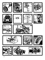 2
2
-
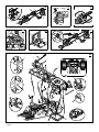 3
3
-
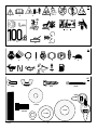 4
4
-
 5
5
-
 6
6
-
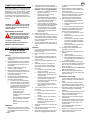 7
7
-
 8
8
-
 9
9
-
 10
10
-
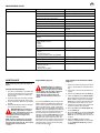 11
11
-
 12
12
-
 13
13
-
 14
14
-
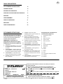 15
15
-
 16
16
-
 17
17
-
 18
18
-
 19
19
-
 20
20
-
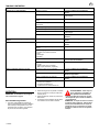 21
21
-
 22
22
-
 23
23
-
 24
24
-
 25
25
-
 26
26
-
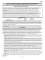 27
27
-
 28
28
-
 29
29
-
 30
30
-
 31
31
-
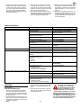 32
32
-
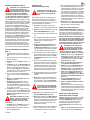 33
33
-
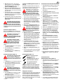 34
34
-
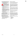 35
35
-
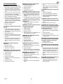 36
36
-
 37
37
-
 38
38
-
 39
39
-
 40
40
-
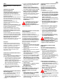 41
41
-
 42
42
-
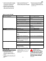 43
43
-
 44
44
-
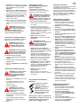 45
45
-
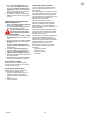 46
46
-
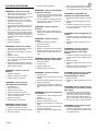 47
47
-
 48
48
-
 49
49
-
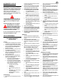 50
50
-
 51
51
-
 52
52
-
 53
53
-
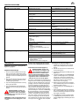 54
54
-
 55
55
-
 56
56
-
 57
57
-
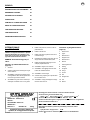 58
58
-
 59
59
-
 60
60
-
 61
61
-
 62
62
-
 63
63
-
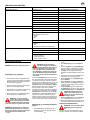 64
64
-
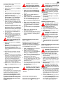 65
65
-
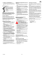 66
66
-
 67
67
-
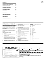 68
68
-
 69
69
-
 70
70
-
 71
71
-
 72
72
-
 73
73
-
 74
74
-
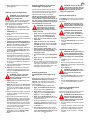 75
75
-
 76
76
-
 77
77
-
 78
78
-
 79
79
-
 80
80
-
 81
81
-
 82
82
-
 83
83
-
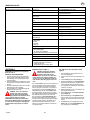 84
84
-
 85
85
-
 86
86
-
 87
87
-
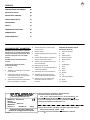 88
88
-
 89
89
-
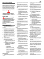 90
90
-
 91
91
-
 92
92
-
 93
93
-
 94
94
-
 95
95
-
 96
96
-
 97
97
-
 98
98
-
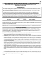 99
99
-
 100
100
-
 101
101
-
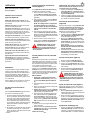 102
102
-
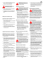 103
103
-
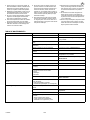 104
104
-
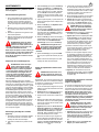 105
105
-
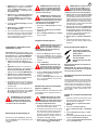 106
106
-
 107
107
-
 108
108
-
 109
109
-
 110
110
-
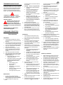 111
111
-
 112
112
-
 113
113
-
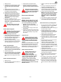 114
114
-
 115
115
-
 116
116
-
 117
117
-
 118
118
-
 119
119
-
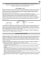 120
120
-
 121
121
-
 122
122
-
 123
123
-
 124
124
-
 125
125
-
 126
126
-
 127
127
-
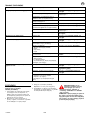 128
128
-
 129
129
-
 130
130
-
 131
131
-
 132
132
-
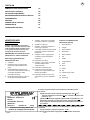 133
133
-
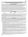 134
134
-
 135
135
-
 136
136
-
 137
137
-
 138
138
-
 139
139
-
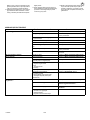 140
140
-
 141
141
-
 142
142
-
 143
143
-
 144
144
-
 145
145
-
 146
146
-
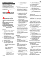 147
147
-
 148
148
-
 149
149
-
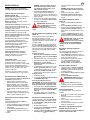 150
150
-
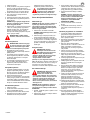 151
151
-
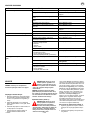 152
152
-
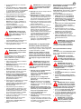 153
153
-
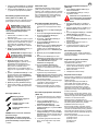 154
154
-
 155
155
-
 156
156
-
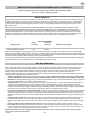 157
157
-
 158
158
-
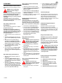 159
159
-
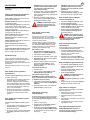 160
160
-
 161
161
-
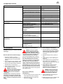 162
162
-
 163
163
-
 164
164
-
 165
165
-
 166
166
-
 167
167
-
 168
168
-
 169
169
-
 170
170
-
 171
171
-
 172
172
-
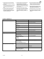 173
173
-
 174
174
-
 175
175
-
 176
176
-
 177
177
-
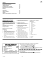 178
178
-
 179
179
-
 180
180
-
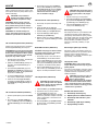 181
181
-
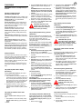 182
182
-
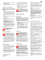 183
183
-
 184
184
-
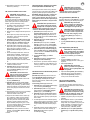 185
185
-
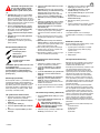 186
186
-
 187
187
-
 188
188
-
 189
189
-
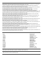 190
190
-
 191
191
-
 192
192


Simplicity 405627X51A Användarmanual
- Kategori
- Gräsklippare
- Typ
- Användarmanual
- Denna manual är också lämplig för
på andra språk
- italiano: Simplicity 405627X51A Manuale utente
- čeština: Simplicity 405627X51A Uživatelský manuál
- eesti: Simplicity 405627X51A Kasutusjuhend
- español: Simplicity 405627X51A Manual de usuario
- Deutsch: Simplicity 405627X51A Benutzerhandbuch
- polski: Simplicity 405627X51A Instrukcja obsługi
- français: Simplicity 405627X51A Manuel utilisateur
- English: Simplicity 405627X51A User manual
- dansk: Simplicity 405627X51A Brugermanual
- suomi: Simplicity 405627X51A Ohjekirja
- Nederlands: Simplicity 405627X51A Handleiding
Relaterade papper
-
Simplicity 10.5HP AND 30IN Användarmanual
-
-
-
Murray Lawn Mower 385048x51A Användarmanual
-
Murray 405628x51A Användarmanual
-
-
-