
Microphone precautions
• This system receives the driver’s voice from
the microphone. When it is noisy outside your
car, shut the windows. Engine noise may also
prevent the system from recognizing the
driver’s voice.
• This microphone can receive sound from one
direction only (directional microphone).
Therefore it is important to install the
microphone properly to ensure the driver’s
voice will be received.
Observera beträffande
mikrofonen
• Systemet tar emot förarens röst från
mikrofonen. När det är bullrigt utanför bilen
bör du stänga fönstren. Motorljud kan också
hindra systemet från att känna igen förarens
röst.
• Mikrofonen kan ta emot ljud endast från en
riktning (mikrofon för ljudupptagning i en
riktning). Det är därför viktigt att installera
mikrofonen korrekt för att garantera att
förarens röst kan tas emot.
Precauciones sobre el
micrófono
• Este sistema recibe la voz del conductor
mediante el micrófono. Si hay ruido en el
exterior, cierre las ventanillas del automóvil.
El ruido del motor puede igualmente impedir
que el sistema reconozca la voz del conductor.
• Este micrófono puede recibir el sonido sólo
desde una dirección (micrófono direccional).
Por tanto, es importante que lo instale
adecuadamente con el fin de garantizar la
recepción de la voz del conductor.
Precauções relativas ao
microfone
• Este sistema recebe a voz do condutor através
do microfone. Se houver muito ruído no
exterior, feche as janelas. O ruído do motor
também pode evitar que o sistema reconheça a
voz do condutor.
• Este microfone só recebe o som de uma
direcção (microfone unidireccional). Deste
modo, é importante instalar o microfone
correctamente para garantir a recepção da voz
do condutor.
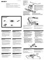
Installing the Microphone
Installation location
• Install the microphone underneath the sun
visor in the pushed up position. Note that
when the sun visor is lowered, the
microphone will not receive the driver’s voice.
• Install the microphone so that the arrow on
the bottom points toward the driver.
Installera mikrofonen
Placering
• Installera mikrofonen under solskyddet när
det befinner sig i uppfällt läge. Observera att
mikrofonen inte kommer att ta emot förarens
röst när solskyddet är nedfällt.
• Installera mikrofonen så att pilen på
underdelen pekar mot föraren.
Instalación del micrófono
Ubicación de instalación
• Instale el micrófono por debajo del parasol en
su posición plegada. Tenga en cuenta que
cuando el parasol no esté plegado, el
micrófono no recibirá la voz del conductor.
• Instale el micrófono de forma que la flecha de
la parte inferior quede orientada hacia el
conductor.
Instalar o microfone
Local de instalação
• Instale o microfone por baixo da pala do sol,
com esta puxada para cima. Quando baixar a
pala do sol, o microfone não recebe a voz do
condutor.
• Instale o microfone de forma a que a seta
existente em baixo aponte para o condutor.
Sony Corporation 1998 Printed in France
3-864-429-11 (1)
Installation for Microphone and Rotary
Commander
Instalación del micrófono y del mando rotativo
Installation av mikrofon och vridkontroll
Instalação do microfone e do comando rotativo
Parts for installation
Componentes de instalación
Delar för installation
Peças para instalação
BA C
(3)
DE
Install the microphone so that the arrow
on the bottom points toward the driver.
Instale el micrófono de forma que la
flecha de la parte inferior quede
orientada hacia el conductor.
Installera mikrofonen så att pilen på
underdelen pekar mot föraren.
Instale o microfone de forma a que a
seta da parte de baixo aponte para o
condutor.
Secure the microphone's
cord as illustrated.
Fije el cable del micrófono
como se ilustra.
Sätt fast mikrofonsladden
på det sätt som visas i
bilden.
Prenda o cabo do
microfone como se mostra
na figura.
Be sure to leave some slack in the microphone's
cord between the microphone and the holder as
illustrated.
Asegúrese de dejar cierta holgura en el cable
del micrófono entre éste y el soporte como se
ilustra.
Se till så att mikrofonsladden inte är allför hårt
spänd mellan mikrofonen och hållaren (se
bilden).
Verifique se existe uma folga no cabo do
microfone entre o microfone e o suporte como
se mostra na figura.
D
Secure the microphone's cord as illustrated.
Fije el cable del micrófono como se ilustra.
Sätt fast mikrofonsladden på det sätt som visas i bilden.
Prenda o cabo do microfone como se mostra na figura.
‘K3 × 12
(2)
When you leave your car
Hide the microphone over the sun visor as
illustrated to protect the microphone from being
stolen.
När du lämnar bilen
Skydda mikrofonen från stöld genom att gömma
den bakom solskyddet (se bilden).
Cuando abandone el automóvil
Oculte el micrófono sobre el parasol como se
ilustra para evitar que roben dicho micrófono.
Quando sair do automóvel
Esconda o microfne na pala como se mostra na
figura para evitar que seja roubado.
Microphone
Micrófono
Mikrofon
Microfone
D
Connecting the microphone
1 Connect the microphone to the MIC jack
of the audio equipment. (Refer to the
“Installation/Connectinos” supplied with
the unit as well.)
2 Bndle up the connecting cord of the
microphone with other connecting cords
of the audio equipment by attaching the
supplied cramper C. Be sure to leave
some slack in the connecting cord
between the plug and the cramper.
Ansluta mikrofonen
1 Anslut mikrofonen till ljudutrustningens
MIC-uttag. (Mer information finns i den
medföljande Montering/Anslutning)
2 Bunta ihop mikrofonens anslutningskabel
med andra anslutningskablar på
ljudutrustningen genom att sätta fast
kabelklämma C (medföljer). Se till att det
finns ett visst utrymme på
anslutningskabeln mellan kontakten och
klämman.
Secure the wire to the window frame so that the
wire does not interfere with driving. Before
attaching the clamp E, clean the surface
thoroughly.
Fäst kabeln mot fönsterramen så att den inte stör
körningen. Se till att göra ren ytan ordentligt
innan du sätter fast klämma E.
Fije el cable en el marco de la ventanilla de forma
que dicho cable no interfiera en la conducción.
Antes de fijar la abrazadera E, limpie a fondo la
superficie.
Fixe o fio na moldura da janela para que não
interfira com a condução. Antes de colocar o
grampo E, limpe bem a superfície.
Conexión del micrófono
1 Conecte el micrófono a la toma MIC del
equipo de audio. (Consulte también el
documento “Instalación/Conexiones”
suministrado con la unidad.)
2 Agrupe el cable de conexión del
micrófono con el resto de cables de
conexión del equipo de audio mediante el
fijador de cables C suministrado.
Asegúrese de dejar cierta holgura en el
cable de conexión entre el enchufe y
dicho fijador.
Ligar o microfone
1 Ligue o microfone à ficha MIC do
equipamento de audio. (consulte o
manual «Instalação/Ligações» fornecido
com o aparelho).
2 Ate o cabo de ligação do microfone com
os outros cabos de ligação do
equipamento de audio instalando uma
braçadeira C. Deixe uma folga no cabo de
ligação entre a ficha e a braçadeira.
C
MIC
E

1 Escolha o local exacto onde deseja montar
o comando rotativo e depois limpe a
superfície de montagem.
A sujidade ou o óleo diminui as capacidades
adesivas da fita adesiva dupla.
2 Marque a posição para o parafuso
fornecido.
Para marcar a posição, utilize o orifício do
parafuso do material de montagem B.
Se a peça B não encaixar com facilidade,
corte-o de forma a ajustar-se à coluna da
direcção.
3 Retire a cobertura da coluna da direcção e
faça furos com 2 mm de diâmetro nos
locais marcados.
4 Aqueça a superfície de montagem e a fita
adesiva dupla da peça B até uma
temperatura de 20 °C a 30 °C, e fixe a peça
na superfície respectiva exercendo uma
pressão uniforme. Em seguida, fixe com o
parafuso A fornecido.
Coloque um pouco de fita adesiva, etc. no
outro lado da superfície de montagem para
tapar as protuberâncias dos parafusos, de
forma a que estes não interfiram com os
cabos eléctricos, etc., localizados no interior
da coluna da direcção.
5 Após a instalação da cobertura da coluna
da direcção, fixe o comando rotativo à
peça, alinhando os quatro orifícios da
extremidade inferior do comando com as
quatro buchas da peça e fazendo deslizar
o comando até que este se fixe
correctamente, conforme o ilustrado.
Nota
Se montar o comando rotativo na coluna da
direcção, certifique-se de que as
protuberâncias dos parafusos na superfície
interior da coluna não prejudicam ou
interferem com o movimento do eixo
rotativo, com as partes operativas dos
comutadores ou com os cabos eléctricos, etc.,
localizados no interior da coluna.
6 Depois de ter efectuado a ligação, una o
cabo de ligação do comando aos outros
cabos de ligação do equipamento áudio
mediante a utilização da braçadeira C
fornecida. Deixe alguma folga no cabo de
ligação entre a ficha e a braçadeira,
conforme a ilustração.
Instalação do comando
rotativo
Notas
• Seleccione cuidadosamente o local de
montagem de forma a que o comando rotativo
não interfira com a condução do automóvel.
• Não instale o comando rotativo em locais onde
este possa, por algum motivo, pôr em perigo a
segurança do passageiro da frente.
• Quando da instalação do comando rotativo,
certifique-se de que não danifica os fios
eléctricos, etc., localizados no outro lado da
superfície de montagem.
• Evite instalar o comando rotativo em locais em
que este fique exposto a temperaturas elevadas
causadas, por exemplo, pela incidêndia directa
dos raios solares, pelo ar quente do
aquecimento, etc.
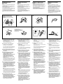
Installing the rotary
commander
Notes
• Choose the mounting location carefully so that
the rotary commander will not interfere with
operating the car.
• Do not install the rotary commander in a place
where it may jeopardize the safety of the
(front) passenger in anyway.
• When installing the rotary commander, be sure
not to damage the electrical cables etc. on the
other side of the mounting surface.
• Avoid installing the rotary commander where it
may be subject to high temperatures, such as
from direct sunlight or hot air from the heater
etc.
1 Choose the exact location for the rotary
commander to be mounted, then clean
the mounting surface.
Dirt or oil impair the adhesive strength of
the double-sided adhesive tape.
2 Mark position for the supplied screw.
Use the screw hole on the mounting
hardware B to mark the position.
If you cannot make the mounting hardware
B fit easy; cut the mounting hardware B to
fit the steering wheel column cover.
3 Remove the steering wheel column cover,
and drill 2 mm diameter hole where you
have marked.
4 Warm the mounting surface and the
double-sided adhesive tape on the
mounting hardware B to the
temperature of 20 °C to 30 °C, and attach
the mounting hardware onto the
mounting surface by applying even
pressure. Then screw it down with the
supplied screw A.
Attach a piece of heavy duty tape etc. on the
other side of the mounting surface to cover
the protruding tips of the screws so that they
will not interfere with the electrical cables
etc. inside the steering wheel column.
5 After installing the steering wheel column
cover, attach the rotary commander to the
mounting hardware by aligning the four
holes on the bottom of the rotary
commander to the four catches on the
mounting hardware and sliding the rotary
commander until it locks into place as
illustrated.
Note
If you are mounting the rotary commander
to the steering wheel column, make sure that
the protruding tips of the screws on the inner
surface of the column do not in anyway
hinder or interfere with the movement of the
rotating shaft, operative parts of the switches
or the electrical cables etc. inside the column.
6 After connecting, bundle up the
connecting cord of the rotary remote with
other connecting cords of the audio
equipment by attaching the supplied
cramper C. Be sure to leave some slack in
the connecting cord between the plug
and the cramper as illustrated.
1 Välj var du vill montera vridkontrollen och
rengör ytan.
Smuts eller olja minskar den dubbelsidiga
tejpens fästförmåga.
2 Markera var du ska borra hål för
skruvarna.
Du kan göra markeringen utifrån skruvhålet
på monteringsdelen B.
Om du inte får monteringsdelen B att passa;
skär den B så att den passar höljet som
skyddar rattens styrstång.
3 Ta loss höljet som skyddar rattens
styrstång och borra hål med 2 mm
diameter där du har gjort markeringarna.
4 Värm monteringsytan och den
dubbelsidiga tejpen på monteringsdelen
B till mellan 20 °C och 30 °C och tryck fast
monteringsdelen. Skruva sedan fast den
med den medföljande skruven A.
Använd maskeringstejp för att täcka över
skruvspetsarna på monteringsytans baksida
så att de inte skaver mot elkablar eller
liknande innanför styrstångens hölje.
5 När du har satt tillbaka styrstångshöljet
fäster du vridkontrollen på
monteringsdelen genom att justera de
fyra hålen på kontrollens undersida efter
de fyra spärrarna på monteringsdelen och
skjuta ned kontrollen tills den låses på
plats, se bilden.
Observera
Om du monterar vridkontrollen på höljet till
rattens styrstång måste du se till att de
utskjutande skruvspetsarna inuti höljet inte
hindrar styrningen av bilen eller kommer i
vägen för annan utrustning eller elkablarna
inuti höljet.
6 När du är klar fäster du ihop sladden till
vridkommandot och andra sladdar till
ljudutrustningen med medföljande
krampa C. Se till så att sladdarna mellan
kontakten och fästanordningen inte blir
för hårt spända, se bilden.
Installera vridkontrollen
Observera
• Var noga med var du monterar vridkontrollen
så att den inte är i vägen när du kör.
• Installera inte vridkontrollen där den utgör en
säkerhetsrisk för passagerare i framsätet.
• Var försiktig när du installerar vridkontrollen så
att du inte skadar elkablar eller liknande på
monteringsytans baksida.
• Undvik att installera vridkontrollen så att den
utsätts för höga temperaturer, direkt solljus
eller stark värme från värmefläkten osv.
1 Una vez elegido el lugar de montaje del
mando rotativo, limpie previamente la
superficie de montaje.
La suciedad o la grasa dañan la intensidad
adhesiva de la cinta adhesiva de dos caras.
2 Marque la posición para el tornillo
suministrado.
Para ello, utilice el orificio para tornillo de la
ferretería de montaje B.
Si no es posible instalar con facilidad la pieza
B, córtela de forma que encaje en la cubierta
de la columna de la dirección.
3 Extraiga la cubierta de la columna de la
dirección y haga orificios de 2 mm. de
diámetro en los lugares marcados.
4 Caliente la superficie de montaje y la cinta
adhesiva de doble cara de la ferretería de
montaje B a una temperatura entre 20 °C
y 30 °C, y ajuste la ferretería de montaje a
la superficie de montaje ejerciendo una
presión uniforme. A continuación, apriete
el tornillo A suministrado.
Adhiera un trozo de cinta adhesiva
resistente, etc. en el otro lado de la superficie
de montaje para cubrir los extremos de los
tornillos que sobresalgan, de forma que no
interfieran con los cables de electricidad, etc.,
del interior de la columna de dirección.
5 Una vez instalada la cubierta de la
columna de dirección, fije el mando
rotativo a la ferretería de montaje
alineando los cuatro orificios de la parte
inferior del mando con los cuatro
enganches de la ferretería de montaje. A
continuación, deslice el mando hasta que
encaje en su sitio como se muestra en la
ilustración.
Nota
Si monta el mando rotativo en la columna de
dirección, asegúrese de que los extremos de
los tornillos que sobresalgan de la superficie
interior de la columna no dificulten el
movimiento del eje de rotación ni los
componentes operativos de los
conmutadores o los cables de electricidad,
etc., del interior de la columna.
6 Una vez realizada la conexión, recoja el
cable de conexión del mando con el resto
de los cables de conexión del equipo de
audio mediante el fijador de cables C
suministrado. Como muestra la
ilustración, procure dejar un espacio en el
cable de conexión entre el enchufe y el
fijador de cables.
Instalación del mando
rotativo
Notas
• Elija cuidadosamente el lugar de montaje de
forma que el mando rotativo no dificulte la
conducción del coche.
• No instale el mando rotativo en un lugar donde
pueda poner en peligro la seguridad del
pasajero acompañante.
• Al instalar el mando rotativo, asegúrese de no
dañar los cables de electricidad, etc., del otro
lado de la superficie de montaje.
• Procure no instalar el mando rotativo en un
lugar expuesto a altas temperaturas, como a la
luz solar directa o al aire caliente de la
calefacción, etc.
12
Marks
Marcas
Markeringar
Marcas
3
4
Heavy duty tape etc.
Cinta adhesiva resistente, etc.
Maskeringstejp eller liknande
Fita adesiva, etc.
5
B
A
6
C
Holes
Orificios
Hål
Furos
Example of a mounting location
Ejemplo de un lugar de montaje
Montering
Exemplo de um local para montagem
B
REMOTE IN
-
 1
1
-
 2
2


på andra språk
- español: Sony MDX-C8900R Guía de instalación
- português: Sony MDX-C8900R Guia de instalação
- English: Sony MDX-C8900R Installation guide