Yamaha DPX-1000 Bruksanvisning
- Kategori
- Dataprojektorer
- Typ
- Bruksanvisning

YAMAHA ELECTRONICS CORPORATION, USA 6660 ORANGETHORPE AVE., BUENA PARK, CALIF. 90620, U.S.A.
YAMAHA CANADA MUSIC LTD. 135 MILNER AVE., SCARBOROUGH, ONTARIO M1S 3R1, CANADA
YAMAHA ELECTRONIK EUROPA G.m.b.H. SIEMENSSTR. 22-34, 25462 RELLINGEN BEI HAMBURG, F.R. OF GERMANY
YAMAHA ELECTRONIQUE FRANCE S.A. RUE AMBROISE CROIZAT BP70 CROISSY-BEAUBOURG 77312 MARNE-LA-VALLEE CEDEX02, FRANCE
YAMAHA ELECTRONICS (UK) LTD. YAMAHA HOUSE, 200 RICKMANSWORTH ROAD WATFORD, HERTS WD1 7JS, ENGLAND
YAMAHA SCANDINAVIA A.B. J A WETTERGRENS GATA 1, BOX 30053, 400 43 VÄSTRA FRÖLUNDA, SWEDEN
YAMAHA MUSIC AUSTRALIA PTY, LTD. 17-33 MARKET ST., SOUTH MELBOURNE, 3205 VIC., AUSTRALIA
Printed in Japan WA00290
DPX–1000
Digital Cinema Projector
Projecteur Cineme Numerique
GB
OWNER’S MANUAL
MODE D’EMPLOI
BEDIENUNGSANLEITUNG
MANUALE DI ISTRUZIONI
MANUAL DE INSTRUCCIONES
DPX-1000
000_DPX-1000(GB)H14 03.3.10, 9:32 AM2

Caution: Read this before operating this unit.
• To assure the finest performance, please read this manual
carefully. Keep it in a safe place for future reference.
Installation
• Install this unit in a well-ventilated, cool, dry, clean place with
at least 30 cm (1 feet) clearance on the top, right and left, and
at the back of this unit — away from direct sunlight, heat
sources, vibration, dust, moisture, and/or cold.
• Locate this unit away from other electrical appliances, motors,
or transformers to avoid humming sounds. To prevent fire or
electrical shock, do not place this unit where it may get
exposed to rain, water, and/or any type of liquid.
• Do not expose this unit to sudden temperature changes from
cold to hot, and do not locate this unit in an environment with
high humidity (i.e. a room with a humidifier) to prevent
condensation inside this unit, which may cause an electrical
shock, fire, damage to this unit, and/or personal injury.
• On the top of this unit, do not place:
– Other components, as they may cause damage and/or
discoloration on the surface of this unit.
– Burning objects (i.e. candles), as they may cause fire,
damage to this unit, and/or personal injury.
– Containers with liquid in them, as they may cause electrical
shock to the user and/or damage to this unit.
• Do not cover this unit with a newspaper, tablecloth, curtain, etc.
in order not to restrict heat dissipation. If the temperature inside
this unit rises too much, it may cause fire, damage to this unit,
and/or personal injury.
• When installing this unit on the ceiling, make sure the ceiling
has sufficient strength to support this unit and the ceiling
mounts for an extended period of time. Installation must be
performed only by qualified service personnel.
Operation
• Remove the lens cover before starting any operation of this unit
to prevent the heat from staying around the lens. Operation
with the cap on may cause damage to this unit.
• Do not plug in this unit to a wall outlet until all connections are
complete.
• Only the voltage specified on this unit must be used. Using this
unit with a higher voltage than specified is dangerous and may
cause fire, damage to this unit, and/or personal injury.
YAMAHA will not be held responsible for any damage
resulting from use of this unit with a voltage other than that
specified.
• Do not use force on switches, knobs and/or cords.
• Do not operate this unit upside-down. It may overheat, possibly
causing damage.
• Take care of this unit so that no foreign objects and/or liquid
drop inside this unit.
• To prevent damage by lightning, disconnect the power cord
from the wall outlet during an electrical storm.
• Do not look into the lens while this unit is turned on. It may
cause serious damage to your eyesight.
• Before moving this unit, press STANDBY/ON to set this unit
in the standby mode, and disconnect the AC power plug from
the wall outlet.
• Do not attempt to modify or fix this unit. Contact qualified
YAMAHA service personnel when any service is needed. The
cabinet should never be opened for any reason.
• When not planning to use this unit for a long period of time
(i.e. vacation), disconnect the AC power plug from the wall
outlet.
• When disconnecting the power cord from the wall outlet, grasp
the plug; do not pull the cord.
• Be sure to read the “TROUBLESHOOTING” section on
common operating errors before concluding that this unit is
faulty.
Others
• Clean the lens carefully so as not to create any scratches by
using a blower or lens paper.
• Replace the lamp when the LAMP warning indicator blinks in
red after the lamp usage has exceeded 2000 hours. Follow the
lamp replacement procedure described in this manual.
For U.K. customers
IMPORTANT
THE WIRES IN THIS MAINS LEAD ARE COLOURED IN
ACCORDANCE WITH THE FOLLOWING CODE:
GREEN-AND-YELLOW: EARTH
BLUE: NEUTRAL
BROWN: LIVE
As the colours of the wires in the mains lead of this apparatus may
not correspond with the coloured markings identifying the
terminals in your plug, proceed as follows:
The wire which is coloured GREEN-AND-YELLOW must be
connected to the terminal in the plug which is marked by the letter
E or by the safety earth symbol or coloured GREEN or GREEN-
and-YELLOW.
The wire which is coloured BLUE must be connected to the
terminal which is marked with the letter N or coloured BLACK.
The wire which is coloured BROWN must be connected to the
terminal which is marked with the letter L or coloured RED.
If the socket outlets in the home are not suitable for the plug
supplied with this appliance, it should be cut off and an appropriate
3 pin plug fitted. For details, refer to the instructions described
below.
Note
• The plug severed from the mains lead must be destroyed, as a plug with
bared flexible cord is hazardous if engaged in a live socket outlet.
For Canadian customers
To prevent electric shock, match wide blade of plug to
wide slot and fully insert.
This Class B digital apparatus complies with Canadian ICES-
003.
I
100_DPX-1000(E)Caut_GB 03.3.5, 6:09 PM2

English
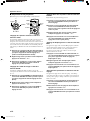
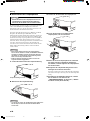
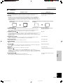
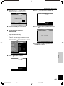
If this unit is not correctly installed in an appropriate place, it may cause fire or failure, or damage the unit itself. Carefully choose the place
to install this unit by avoiding the places listed below.
1. Places where the temperature and humidity vary greatly
• Do not install this unit in a place where the temperature and humidity become extremely high or the temperature becomes extremely
low.
• This unit must be used within a temperature range of 5—35°C.
2. Places without adequate ventilation
• Install this unit with at least 30 cm (1 feet) of ventilation space on the top, right and left, and back.
• Do not cover the ventilation slots of this unit not to obstruct the heat dissipation.
• Install this unit on the firm surface.
• Do not cover this unit with a tablecloth, etc.
• Make sure there is nothing to get sucked into the ventilation slots so that the temperature of this unit does not become too high.
• If you are going to install the unit in a rack, be sure to leave space for ventilation to prevent exhaust overheating the unit.
3. Places where it gets dusty
• If the filter is blocked with dust, the temperature of this unit may become too high.
4. Places with too much vibration or impact
• Vibration and impact can damage parts of this unit.
5. Places where this unit gets exposed to water or high humidity
• If this unit is exposed to water or high humidity, it may cause a fire or electrical shock.
6. Unstable places
• If this unit is installed on an unstable or an inclined tabletop, it may fall and cause damage to the unit or personal injury.
7. In close proximity to a Radio or Stereo
• The unit may interfere with reception if placed in close proximity to a radio or television receiver.
Important
• To ensure vivid, high contrast images, make sure that no light other than the projector light falls directly on the screen.
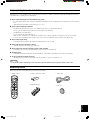
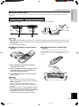
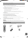
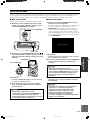
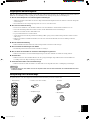
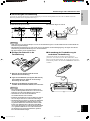
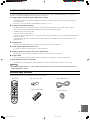
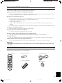
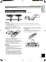
Accessory check
Please check that all accessories listed here are included in your package.
Inappropriate places for installation
II
45
RESET
6
123
VIDEO
STILL HIDE
INPUT
MENU
PATTIRIS
AUTO
SETTING
ASPECT
ZOOM FOCUSV. POS
ESCAPE
LIGHT
BD4
S VIDEO
A
INPUT
MEMORY
DVI
• Remote control • Batteries (AA, UM-3 or R6)
• Pin/BNC adapters
• Power cable
• Lens cover
100_DPX-1000(E)Caut_GB 03.3.5, 6:09 PM3

E-1
INTRODUCTION
INSTALLATION
CONNECTIONS
BASIC OPERATION
MENU
ADDITIONAL
INFORMATION
English
ENGLISH
Features
Contents
• Bright, high contrast images achieved through
DLP™ technology
• HDTV capable 1280 x 720 pixel wide DMD™
element
• A bright, high resolution large diameter lens
• Electronic lens adjustment
— Zoom, Focus, Vertical Position, Optical Iris
Diaphragm —
(DLP™ and DMD™ are trademarks of Texas Instruments.)
• Low operating noise made possible by Yamaha
sound technology
• High quality progressive reproduction of film
sources thanks to 3-2 pulldown detection
• 6 memory settings and an abundance of image
adjustment functions
• Digital Visual Interface (DVI)
HDCP Compatible
INTRODUCTION
Features ............................................. 1
Part Names and Functions
Front panel and controls ....................................................... 2
Connections .......................................................................... 3
Remote control ..................................................................... 4
Using the remote control ...................................................... 5
Loading the batteries into the remote control ....................... 5
Using the remote as a wired remote control ......................... 5
INSTALLATION
Installation
Installation methods ............................................................. 6
Screen and projection distance ............................................. 7
Projection image position ..................................................... 8
Keystone ............................................................................... 8
CONNECTIONS
Connecting the unit
Connecting A/V components ................................................ 9
Connecting to a computer ................................................... 10
BASIC OPERATION
Basic Operations
Turning on the power ......................................................... 11
Turning off the power ......................................................... 11
Preparations for projection ................................................. 12
Select an input .................................................................... 13
Select a display aspect ........................................................ 14
Other functions ................................................................... 15
Indicators ............................................................................ 15
MENU
Menu structure ................................... 16
1 <IMAGE> ...................................................................... 17
2 <SIGNAL> .................................................................... 19
3 <INITIAL> .................................................................... 20
4 <SETUP> ...................................................................... 21
Menu operation
Menu screen and operating buttons .................................... 22
Basic menu operation ......................................................... 23
Submenus ........................................................................... 24
Basic submenu operation .................................................... 25
One-touch image menu ...................................................... 28
Changing the menu location ............................................... 28
Memory function
Selecting the memory setting number ................................ 29
Resetting to the factory default settings ............................. 30
ADDITIONAL INFORMATION
Additional information
Glossary .............................................................................. 31
Projectable signals .............................................................. 33
Message display ................................................................. 34
Maintenance
Regular care ........................................................................ 35
Filter replacement ............................................................... 35
Replacing the lamp cartridge .............................................. 36
Troubleshooting .................................. 37
Specifications
Specifications ..................................................................... 38
Dimensional drawing ......................................................... 39
101_DPX-1000(E)01-05 03.3.5, 6:10 PM1

E-2
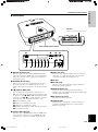
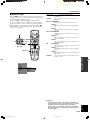
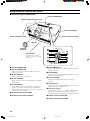
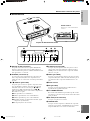
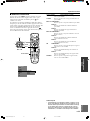
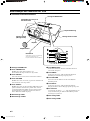
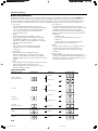
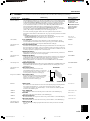
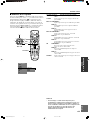
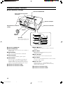
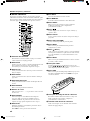
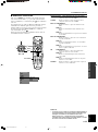
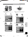
Part Names and Functions
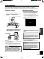
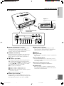
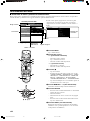
1 STANDBY/ON indicator
2 STANDBY/ON button
Switches the unit between Standby and On (operational)
modes.
3 ESCAPE button
Use this button to exit from submenu mode.
4 PATTERN button
Switches the built-in test pattern display on and off.
5 ASPECT button
Selects the display aspect of the projection image. Press the
button to display the aspect presently being used. Pressing the
button again within 2 seconds will switch the unit to the next
aspect mode.
6 LAMP warning indicator
7 COVER warning indicator
■ Front panel and controls
STANDBY
/
ON
SETTING
LAMP COVER TEMP FAN
PATTERN
ESCAPE
MENU
INPUT
DIGITAL CINEMA PROJECTOR DPX-1000
ASPECT
1
2
3
4
5
6
7
8
9
0
q
w
e
r
Front remote control sensor
STANDBY/ON indicator
Ventilation (Exhaust) vent
Lens cover
Lens
Adjuster
Use this to make fine adjustments
to the projection angle.
8 (Enter) button
Press this button to set values and enter into submenus.
9 MENU button
Press this button to display the general settings and adjustments
menu.
0 SETTING button
Selects the various lens adjustment modes.
q INPUT button
Press this button to display the input source and input signal
selection menu.
w Cursor button
Use the h, g, –, + buttons for functions such as system
operations, menu item selection, and changing system values.
e FAN warning indicator
r TEMP warning indicator
Ventilation inlet
Lamp cover
101_DPX-1000(E)01-05 03.3.5, 6:10 PM2

E-3
INTRODUCTION
English
DVI
INPUT B
RGB/YP
B
P
R
/YC
B
C
R
D4 VIDEO G/Y B/P
B
/C
B
R/P
R
/C
R
INPUT A
HD/SYNC VD
OUT IN
REMOTE
RS-232C
S-VIDEO VIDEO
TRIGGER OUT
q
1234567 809
wer
DVI
INPUT B
RGB/YP
BPR/YCBCR
D4 VIDEO G/Y B/PB/CB R/PR/CR
INPUT A
HD/SYNC VD
OUT IN
REMOTE
RS-232C
S-VIDEO VIDEO
TRIGGER OUT
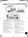
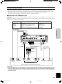
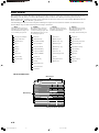
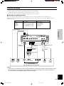
1 INPUT B (D-Sub 15 pin)
This is the input connector for signals (RGB/YPBPR/YCBCR)
from a component video or RGB source. Use a D-Sub monitor
cable when connecting another component to the DPX-1000
through this connector.
2 D4 VIDEO (D connector)
This connector receives video signals from the D connector of
other A/V components. It is compatible with the D1—D4
formats. (This connector is designed for the Japanese D format
only.)
3—7 INPUT A (BNC jacks)
These are input jacks for signals from component video or
RGB sources. Component signals from A/V equipment should
be connected to ports 3—5, and RGB signals from Computer
equipment to ports 3—7. Use a BNC cable when connecting
other components to the DPX-1000 through these jacks.
3 G/Y (G, or luminance signal)
4 B/P
B/CB (B, or color difference signal)
5 R/P
R/CR (R, or color difference signal)
6 HD/SYNC (horizontal sync signal, composite sync signal)
7 VD (vertical sync signal)
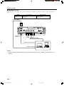
8 S-VIDEO (Mini DIN jack)
This jack receives S VIDEO signals from the S-VIDEO output
jack of other A/V components. Use an S VIDEO cable when
connecting other components to the DPX-1000 through this
jack.
■ Connections
Part Names and Functions
Rear remote control sensor
9 VIDEO (Pin jack)
This jack receives composite signals from jacks of other A/V
components. Use a video pin cable when connecting other
components to the DPX-1000 through this jack.
0 AC inlet
q DVI (DVI jack)
This jack receives DVI signals from computer equipment or
DVI signals from A/V equipments.
w REMOTE IN/OUT jack
Connect the remote control to the IN jack when using it
through a cable. Codes input through the IN jack will be output
directly through the OUT jack.
e RS-232C (D-sub 9 pin)
This jack is used for factory testing.
r TRIGGER OUT
This jack outputs control signals to external components. A
potential of 12V/Maximum 200 mA is provided when the
DPX-1000 is projecting.
AC inlet
Plug in the supplied power cord here.
101_DPX-1000(E)01-05 03.3.5, 6:10 PM3

E-4
Part Names and Functions
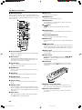
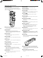
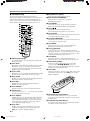
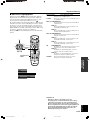
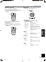
■ Remote control
Buttons with identical names to those on the main unit perform
identical functions. To use the remote, point it at the remote control
sensor on the front or back of the unit from a distance of no more
than 7 m (23 feet).
1 Transmit indicator
This indicator will light up when the unit is sending infra-red
signals to the main unit.
2 AUTO button
Pressing this button will automatically adjust the unit to the
best settings for projection by retuning the frequency of the
projection to that of the source component.
3 V. POS button
Switches on and off the adjustment mode for the vertical
positioning of the entire image.
4 ZOOM button
Switches on and off the size adjustment mode for the image
being projected.
5 IRIS button
Switches on and off the lens iris diaphragm change mode.
6 ESCAPE button
Press this button to exit from a sub-menu.
7 Cursor buttons
Use the h, g, –, + buttons to move the cursor within the
interface.
8 ASPECT button
Selects the display aspect of the projection image. Press the
button to display the aspect presently being used. Pressing the
button again within 2 seconds will switch the unit to the next
aspect mode.
9 STILL button
Stops a moving image to display a still of the desired image.
Press STILL again to cancel this function.
45
RESET
6
123
VIDEO
STILL HIDE
INPUT
MENU
PATTIRIS
AUTO
SETTING
ASPECT
ZOOM FOCUSV. POS
ESCAPE
LIGHT
BD4
S VIDEO
A
INPUT
MEMORY
DVI
p
o
i
u
y
t
r
e
1
2
3
4
5
6
7
8
9
0
q
w
RESET
5
6
1
2
3
V
I
D
E
O
B
D4
S
V
ID
EO
A
D
VI
S
T
I
L
L
A
S
P
E
C
T
E
S
C
A
P
E
HID
E
INPUT
M
ENU
IR
IS
PATT
V. POS
Z
O
O
M
FOCUS
AUTO
4
ID-2
ID-1
a
s
0 INPUT area
Directly selects the input jack.
q MEMORY area
Calls up stored video memory directly.
w RESET button
Press this button to reset all parameters altered in the menu to
their default factory settings.
e button
Switches the unit between Standby and On (operational)
modes.
r FOCUS button
Switches on and off the focus adjustment mode for the image
being projected.
t PATT (PATTERN) button
Switches the built-in test pattern display on and off.
y MENU button
Press this button to display the general settings and adjustments
menu.
u (Enter) button
Use this button to set values and enter into submenus when the
menu is being displayed. Pressing the button when the menu is
not being displayed will call up the in-line menu. (see page 28.)
i INPUT button
Press this button to display the input source and input signal
selection menu.
o LIGHT switch
Pressing this switch will light up the often used 2, 6, 8, e,
y, i buttons. The lights will switch off if no operation is
performed within 10 seconds.
p HIDE button
Press this button to temporarily halt projection of the image
being displayed. Press the HIDE button once more to cancel
this function.
a Remote control code switch
This remote control will work when it has the same code as
that set on the menu. The default setting on the menu is ID-1.
s Remote control cable jack
Use this jack to connect the remote control to the main unit
with a cable.
101_DPX-1000(E)01-05 03.3.5, 6:10 PM4

E-5
INTRODUCTION
English
Part Names and Functions
Important
• Bright light, fluorescent light etc. on the remote sensor on the main unit may inhibit the normal functioning of the remote control.
• The remote may not function normally if there is an obstacle blocking the signal between the remote and the remote control sensor
on the main unit.
• The above are approximate figures.
■ Using the remote control
Use the remote control under the following conditions. The remote control will not function if it is used outside the angles and/or range
detailed here.
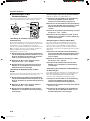
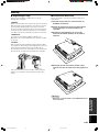
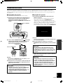
■ Loading the batteries into the remote
control
1. Remove the battery compartment cover from the
back of the remote control.
2. Insert two batteries (AA, UM3, or R6 type), matching
the polarity markings (+, –) on the batteries with
those in the battery compartment.
3. After inserting the batteries, close the cover until it
snaps into place.
Important
• If the remote must be used closer to the main unit than
normal, or does not always operate correctly, exchange the
batteries for new ones.
• Do not mix old and new, or different types of battery.
• Remove the batteries if you do not plan to use the unit for a
long time.
• If the batteries leak, dispose of them immediately, taking care
not to touch the battery fluid. If the battery fluid comes into
contact with your eyes, mouth, or skin, rinse it off with water
immediately and consult a doctor. Clean the battery
compartment thoroughly before installing new batteries.
■ Using the remote as a wired remote
control
To use the remote control as a wired remote control, use a 2P
monaural miniplug to connect the remote control cable jack on the
underside of the remote control to the REMOTE IN jack on the
main unit.
Usable angle
30 degrees
Usable distance
7 m (23 feet)
A left/right arc of 30 degrees A vertical arc of 30 degrees
DVI
INPUT B
RGB/YP
B
P
R
/YC
B
C
R
D4 VIDEO G/Y B/P
B
/C
B
R/P
R
/C
R
INPUT A
HD/SYNC VD
OUT IN
REMOTE
RS-232C
S-VIDEO VIDEO
TRIGGER OUT
45
RESET
6
123
VIDEO
STILL HIDE
INPUT
MENU
PATTIRIS
AUTO
SETTING
ASPECT
ZOOM FOCUSV. POS
ESCAPE
LIGHT
BD4
S VIDEO
A
INPUT
MEMORY
DVI
45
RESET
6
123
VIDEO
STILL HIDE
INPUT
MENU
PATTIRIS
AUTO
SETTING
ASPECT
ZOOM FOCUSV. POS
ESCAPE
LIGHT
BD4
S VIDEO
A
INPUT
MEMORY
DVI
7 m
(23 feet)
7 m (23 feet)
7 m (23 feet)
1
3
2
RES
ET
5
6
1
2
3
V
ID
E
O
B
D
4
S VIDEO
A
D
V
I
S
T
I
L
L
A
SP
EC
T
E
S
C
A
P
E
H
ID
E
INPUT
M
EN
U
IRIS
P
ATT
V
. P
OS
Z
OOM
FOCUS
A
U
T
O
4
ID-1
ID-2
DVI
INPUT B
RGB/YP
B
P
R
/YC
B
C
R
D4 VIDEO G/Y B/P
B
/C
B
R/P
R
/C
R
INPUT A
HD/SYNC VD
OUT IN
REMOTE
RS-232C
S-VIDEO VIDEO
TRIGGER OUT
101_DPX-1000(E)01-05 03.3.5, 6:10 PM5

E-6
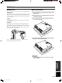
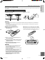
Installation
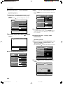
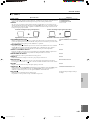
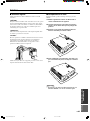
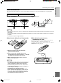
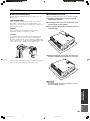
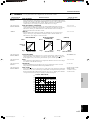
■ Installation methods
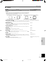
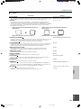
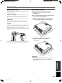
There are four ways to install this unit:
on a table in front of the screen.
mounted on the ceiling in front of the screen.
on a table behind a semi translucent screen.
mounted on the ceiling behind a semi translucent screen.
Set the method you use on the 4 <SETUP> section of the MENU described later. (see page 21.)
<Mounting on a table>
Place the unit on a standard height table to project and view the image
from in front of the screen. The height from the bottom of the unit to the
center of the lens is 12.4 cm (4”-7/8).
<Mounting on the ceiling>
There are two kinds of brackets (low ceiling and high ceiling, sold
separately) available which can be used to mount the unit on the ceiling.
Consult your dealer for details on their use, and have installation done by
either your dealer or a reputable contractor.
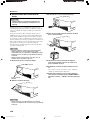
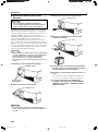
The image on the screen is vertically reversed compared to that of a table
mounted installation. In this case, please set the installation type to
FRONT/CEILING in the 4 <SETUP> section of the menu. (see page
21.)
<Mounting the unit on a table or on the ceiling from behind a semi translucent screen>
In this case, images are projected onto a semi translucent screen, and the
viewer watches it from the reverse side. The relationship with the screen
and projection distance corresponds to that for front projection. For rear
projection, set the installation type to REAR/CEILING or REAR/TABLE
in the 4 <SETUP> section of the menu. (see page 21.)
102_DPX-1000(E)06-08 03.3.5, 6:11 PM6

E-7
English
INSTALLATION
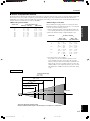
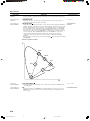
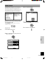
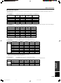
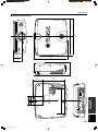
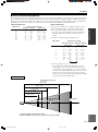
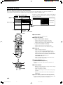
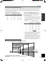
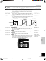
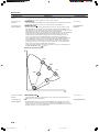
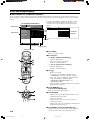
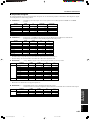
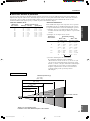
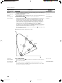
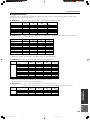
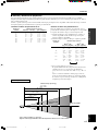
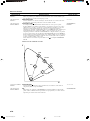
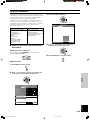
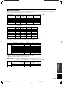
■ Screen and projection distance
The ideal position for mounting the main unit (Projection distance [a]) depends on the size of the screen to be used (the length of a diagonal
line across the screen). It is possible to adjust the projection distance within a preset range from Wide to Tele using the zoom function.
Additionally, it is possible to adjust the V. POS (Vertical positioning) of the image to better suit the screen. Use the information illustrated in
the figure below to determine the best position for installation.
Installation
<When using a 16:9 screen>
Screen size
60
70
80
90
100
110
120
150
200
Wide (m) — Tele (m)
1.8 — 2.88
2.1 — 3.36
2.4 — 3.84
2.7 — 4.32
3.0 — 4.8
3.3 — 5.28
3.6 — 5.76
4.5 — 7.2
6.0 — 9.6
<When using a 4:3 screen>
Since the DPX-1000 is equipped with a 16:9 element, the ideal
installation position for viewing images with a 4:3 screen depends
on the size of the desired image projection.
1 When a standard 16:9 image completely fills the width of the
screen (leaving black line at the top and bottom of the screen)
2 When the standard 4:3 image completely fills the screen
Screen size
60
80
100
120
200
Wide — Tele
(m), (feet, inches)
1.65 m — 2.64 m
5’5” — 8’8”
2.2 m — 3.52 m
7’2” — 11’7”
2.75 m — 4.4 m
9’ — 14’5”
3.3 m — 5.28 m
10’10” — 17’4”
5.5 m — 8.8 m
18’ — 28’10”
Projection distance
Wide — Tele
(m), (feet, inches)
2.2 m — 3.52 m
7’3” — 11’7”
2.9 m — 4.64 m
9’6” — 15’3”
3.65 m — 5.84 m
12’ — 19’2”
4.4 m — 7.04 m
14’5” — 23’1”
7.3 m — 11.68 m
23’11” — 38’4”
3 Projecting both 16:9 and 4:3 images
It is possible to use the zoom function to make use of the
screen efficiently for both 1 and 2 above. The projection
distance in this case will be between Wide in 2 and Tele in 1.
Adjust the size of the projected image using the zoom so that
all images fill the screen completely. However, please be aware
that adjustments to V. POS can cause the position of the image
to slip.
3
60'' 80'' 100'' 150'' 200''
6.0 – 9.6 m
(19'8" – 31'6")
4.5 – 7.2 m
(14'9" – 23'7")
3.0 – 4.8 m
(9'10" – 15'9")
2.4 – 3.84 m
(7'10" – 12'7")
1.8 – 2.88 m
(5'11" – 9'5")
For a 16:9 screen
*These are theoretical numerical values.
Please be aware that there may be some discrepancy in comparison to actual values.
Lens center line
Screen size
Projection distance [a]
12
(feet, inches)
5’11” — 9’5”
6’10” — 11’
7’10” — 12’7”
8’10” — 14’2”
9’10” — 15’9”
10’10” — 17’4”
11’10” — 18’11”
14’9” — 23’7”
19’8” — 31’6”
Projection distance [a]
102_DPX-1000(E)06-08 03.3.5, 6:11 PM7

E-8
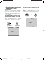
Installation
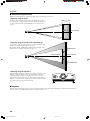
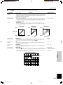
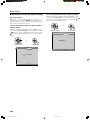
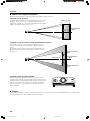
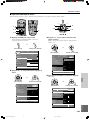
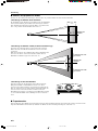
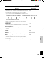
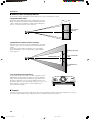
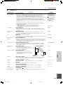
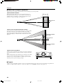
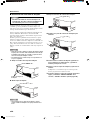
■ Projection image position
Follow the instructions below to adjust the position of the projected image on the screen.
<Adjusting using the zoom>
This figure shows the limits within which the zoom function can alter
projection distance in relation to the screen size. Within these limits, it is
possible to adjust the image so that it fills the screen completely. (See
page 12.)
<Adjusting using the V. POS (vertical positioning)>
It is possible to adjust the vertical position of the projected image on the
screen up or down by half the height of the screen.
For example, shifting V. POS fully up will bring the lower limit of the
image above the centerline of the lens. (See page 12.)
<Adjusting using the adjusters>
When this unit is mounted on a tabletop, the position of the image can be
adjusted by using the adjusters located on the underside of the unit.
Adjust the height by rotating the movable part of the two screw-type
adjusters at the front bottom of the case. The adjustment range of these
adjusters is 3 cm (1-1/4 inch). Adjust with care as loosening them further
may cause them to separate from the main unit.
■ Keystone
When the unit is mounted at an angle to the screen, the image will be projected in a trapezoid manner. Use the keystone function in the
keystone section of 4 <SETUP> in the menu to rectify this. (See page 21.)
Tele
Lens center line
Shifted fully down
Shifted fully up
Lens center line
Projected image
Wide
102_DPX-1000(E)06-08 03.3.5, 6:11 PM8

E-9
CONNECTIONS
English
DVI
INPUT B
RGB/YP
B
P
R
/YC
B
C
R
D4 VIDEO G/Y B/P
B
/C
B
R/P
R
/C
R
INPUT A
HD/SYNC VD
OUT IN
REMOTE
RS-232C
S-VIDEO VIDEO
TRIGGER OUT
G
/
YR
/
P
R
/
C
R
B
/
P
B
/
C
B
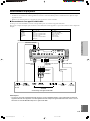
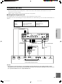
◆ Note ◆
• Make sure to match the Y/PB/PR or Y/CB/CR of the A/V component and this unit when connecting a component to INPUT A compo-
nent jacks. Also, refer to the operation instructions for the A/V component. HD/SYNC and VD need to be connected for RGB video
signals in some cases.
Connecting the unit
• Make sure that the power of this unit and all other components is turned off before making any connections.
• Some components have different connection methods and connector names.
Refer to the operating instructions for each component that you wish to connect.
• Plug the unit in correctly to prevent it from creating noise or other problems.
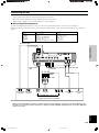
■ Connecting A/V components
As shown in the illustration below, there are 6 types of connections provided on this unit for connection to A/V components.
Follow the instructions on the figure below to connect A/V video outputs from other components to this unit using the correct cables and
adapters.
D connector cable
D-sub monitor
cable
BNC cable for component
connection
Pin/BNC
adapters
Pin cable
Video pin cable
S video cable
D1—4 output
connectors
Pin jacksD-sub
Component/RGB video output connectors
Image output from A/ V components
BNC jacks S video output
jack
Video output
jack
Input
VIDEO
S-VIDEO
INPUT A
INPUT B
D4 VIDEO
DVI
Signal type
Composite video
S video
Component video/RGB video
Component video/RGB video
Component video
Component video/RGB video (digital)
Connector type
Pin jack
Mini DIN connector
BNC connector x 3—5
D-sub 15 pin
D connector
DVI connector
DVI cable (digital)
DVI output
connector
103_DPX-1000(E)09-10 03.3.5, 6:12 PM9

E-10
DVI
INPUT B
RGB/YP
B
P
R
/YC
B
C
R
D4 VIDEO G/Y B/P
B
/C
B
R/P
R
/C
R
INPUT A
HD/SYNC VD
OUT IN
REMOTE
RS-232C
S-VIDEO VIDEO
TRIGGER OUT
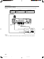
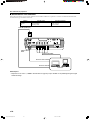
■ Connecting to a computer
There are three ways of connecting a computer, as listed below. Please use the correct type of cable for the connector when making
connections.
Connecting the unit
◆ Note ◆
• Refer to see 2 <SIGNAL> in the menu described on page 19 for detailed settings for the type of image signal input.
DVI cable (Digital)
D-Sub monitor
cable
BNC monitor cable
Monitor output terminal
DVI output terminal
Computer
Input
INPUT A
INPUT B
DVI
Signal type
RGB Analog
RGB Analog
RGB Digital
Connector type
BNC jack x 5
D-sub 15 pin
DVI connector
103_DPX-1000(E)09-10 03.3.5, 6:12 PM10

E-11
BASIC OPERATION
English
Basic Operations
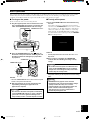
■ Turning on the power
Be sure to remove the lens cover before using this unit.
1. Plug the supplied power cord into the AC inlet on the
rear of the DPX-1000, then plug the cord into the wall
outlet. The STANDBY/ON indicator will turn orange.
2. Press the STANDBY/ON button (The button on
the remote control). The indicator will blink green and
the lamp inside the unit will light up, in preparation
for projection.
◆ Note ◆
• There are STANDBY/ON indicators located on the front panel
and the control panel of the main unit.
3. After approximately 35 seconds, the indicator will
stop blinking, indicating that preparations for
projection are complete.
Important
• Be sure not to disconnect the power cord while the
power STANDBY/ON indicator is green, or blinking
green. This can cause significant damage to the
lamp and may result in a shorter lamp life or failure.
STANDBY/ON indicator
DVI
INPUT B
RGB/YP
B
P
R
/YC
B
C
R
D4 VIDEO G/Y B/P
B
/C
B
R/P
R
/C
R
INPUT A
HD/SYNC VD
OUT IN
REMOTE
RS-232C
S-VIDEO VIDEO
TRIGGER OUT
STANDBY
/
ON
SETTING
LAMP COVER TEMP FAN
PATTERN
ESCAPE
MENU
INPUT
ASPECT
STANDBY/ON indicator
AC inlet
INPUT
MENU
PATTIRIS
AUTO
SETTING
ASPECT
ZOOM FOCUSV. POS
ESCAPE
STANDBY
/
ON
SETTING
LAMP COVER TEMP FAN
PATTERN
ESCAPE
MENU
INPUT
ASPECT
STANDBY ON ( )
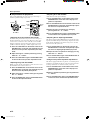
■ Turning off the power
1. Press the STANDBY/ON button when finished using
this unit.
There will be a message to confirm that you wish to turn the
unit off. Press the STANDBY/ON button once more to confirm
that you wish to do so. The lamp will switch to a half-lit state,
and the fan continues for roughly 2 minutes to cool the lamp.
During this time, the STANDBY/ON indicator blinks orange.
You cannot turn the unit on again by pressing the STANDBY/
ON button during this time.
◆ Note ◆
• The lamp may blink when in the half-lit state. This is not a
lamp failure.
2. Once cooling is completed, the STANDBY/ON
indicator will cease blinking, becoming a steady
orange.
Important
• Do not disconnect the power cord when the fan is
going and the STANDBY/ON indicator is blinking
orange. This could damage the lamp and result in
shorter lamp life or lamp failure.
3. Replace the lens cover and disconnect the unit from
the power outlet if you do not plan to use it for a long
time.
Important
• Condensation may appear on the unit if the
temperature of the surround environment changes
quickly. Condensation may also cause the
projected image to be cloudy. Switch off the unit
power until the condensation disappears.
Switching the unit on when condensation is
present may damage the unit.
Press again for standby
This section describes the basic operation of the DPX-1000 once installation and connection have been completed. It is necessary to make
detailed settings in the menu described later so that the DPX-1000 is correctly set for the mounting, screen, input signals, and other
conditions of its installation. Follow the steps described in this section to carry out these procedures.
104_DPX-1000(E)11-15 03.3.5, 6:13 PM11

E-12
Basic Operations
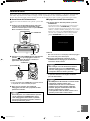
■ Preparations for projection
Carry out the adjustments necessary to the projection image to
obtain the optimum setting for projection.
<Adjusting the vertical position with V. POS>
The initial setting on this unit is for projection of the image in a
line directly from the center of the lens. Where the center of the
screen is above or below the center of this line, use the V. POS
function to adjust the vertical position of the image up or down.
V. POS can adjust the image up to half the height of the screen.
1. Press the V. POS button on the remote control or the
SETTING button on the main unit repeatedly to place
the unit in vertical position adjustment (Lens shift)
mode.
2. Adjust the image to a suitable position by pressing
either the h or g buttons.
3. Press the V. POS button again or the ESCAPE button
to exit from the vertical position adjustment mode.
<Adjusting image size with ZOOM>
Enlarge or reduce the size of the image to fit the size of the screen.
The maximum extent of this zoom is 1:1.6.
1. Press the ZOOM button on the remote control or the
SETTING button on the main unit repeatedly to place
the unit in zoom adjustment (Zoom) mode.
2. Adjust the image to a suitable size by pressing either
the h or g buttons.
3. Press the ZOOM button again or the ESCAPE button
to exit from the adjustment mode.
<Adjusting focus with FOCUS>
Adjust the focus of the projected image.
1. Press the PATT button on the remote control or the
PATTERN button on the main unit to display a test
pattern for adjustment.
2. Press the FOCUS button on the remote control or the
SETTING button on the main unit repeatedly to place
the unit in focus adjustment mode.
3. Adjust the unit to an optimal focus setting by
pressing either the h or g buttons.
4. Press the FOCUS button again or the ESCAPE button
to exit from the focus adjustment (Focus) mode.
<Adjusting the iris diaphragm with IRIS>
This unit is equipped with an IRIS function to switch between the
high levels of black and high contrast images important in a home
theatre and the bright images needed for a large screen. Use this
function as best suits your needs.
1. Press the IRIS button on the remote control or the
SETTING button on the main unit repeatedly to place
the unit in iris diaphragm adjustment (Iris) mode.
2. Adjust the unit to an optimal iris setting by pressing
either the + or – buttons.
3. Press the IRIS button again or the ESCAPE button to
exit from the iris adjustment mode.
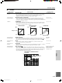
<Using the test pattern to perform adjustments>
This unit is equipped with three test patterns: a crosshatch pattern
useful for focus adjustment, and gray scale and color bar patterns
for image adjustment. Use them as best suits your needs.
1. Press the PATT button on the remote control or the
PATTERN button on the main unit to display a test
pattern for adjustment.
2. Select a suitable test pattern by pressing either the +
or – buttons.
3. Press the PATT button again or the PATTERN button
on the main unit to exit from the adjustment mode.
INPUT
MENU
AUTO
SETTING
ASPECT
ESCAPE
PATTIRIS
ZOOM FOCUSV. POS
PATTIRIS
FOCUS
V. POS
ZOOM
ESCAPE
STANDBY
/
ON
SETTING
LAMP COVER TEMP FAN
PATTERN
ESCAPE
MENU
INPUT
ASPECT
SETTING
ESCAPE
104_DPX-1000(E)11-15 03.3.5, 6:13 PM12

E-13
BASIC OPERATION
English
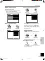
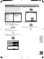
■ Select an input
Press the INPUT button to display the input selection menu on the
screen. Use the h and g to select a name from those on display and
then press the to confirm your choice.
The signal settings for INPUT A, INPUT B and DVI will not
change. To change them, press the + button to open the submenu,
use the cursor buttons to select a suitable source from Component/
RGB PC/RGB TV, and confirm the selection by pressing the
button. You can select the terminal name directly from the input
area on the remote control.
Basic Operations
Input source The image signal to project
VIDEO Composite video signals input from an A/V component to
the VIDEO jack
S-VIDEO S video signals input from an A/V component to the S
VIDEO jack
INPUT A <COMPONENT>
Component signals input to INPUT A (BNC jack)
<RGB PC>
RGB signals input from a computer to INPUT A (BNC
jack)
<RGB TV>
RGB signals input from an A/V component to INPUT A
(BNC jack)
INPUT B <COMPONENT>
Component signals input to the D-sub 15-pin connector
on INPUT B
<RGB PC>
RGB signals input from a computer to the D-sub 15-pin
connector on INPUT B
<RGB TV>
RGB signals input from a component to the D-sub 15-pin
connector on INPUT B
DVI <COMPONENT>
Digital component signals input from an A/V component
to the DVI connector
<RGB PC>
Digital RGB signals input from a computer to the DVI
connector
<RGB TV>
Digital RGB signals input from an A/V component to the
DVI connector
D4 VIDEO Component signals input from an A/V component to the
D4 video connector
INPUT area
45
RESET
6
123
VIDEO
STILL HIDE
INPUT
MENU
PATTIRIS
AUTO
SETTING
ASPECT
ZOOM FOCUSV. POS
ESCAPE
LIGHT
BD4
S VIDEO
A
INPUT
MEMORY
DVI
STANDBY
/
ON
SETTING
LAMP COVER TEMP FAN
PATTERN
ESCAPE
MENU
INPUT
ASPECT
INPUT
+
Input signal
VIDEO
S VIDEO
INPUT A
INPUT B
DVI
D4
Component
RGB PC
RGB TV
Enter
◆ Note ◆
• Setting a laptop or notebook PC to display simultaneously
on its built in display and on an external monitor can cause
the image to be incorrectly displayed on the external
monitor. In this case, set the PC to display on the external
monitor only. Refer to the computer’s operating instructions
for further details.
104_DPX-1000(E)11-15 03.3.5, 6:13 PM13

E-14
Basic Operations
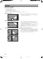
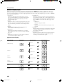
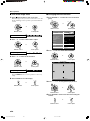
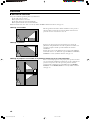
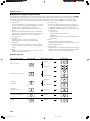
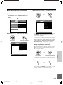
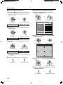
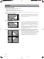
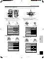
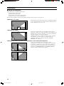
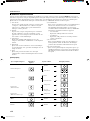
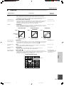
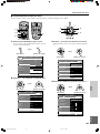
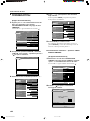
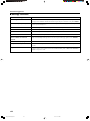
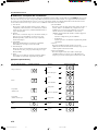
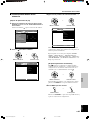
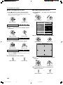
■ Select a display aspect
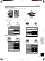
Display aspect selects the type of image to display for an input signal.
Press
the ASPECT button and select a suitable mode. The types of
aspect mode available depend on the input signal. Additionally, this unit has an auto mode that can automatically select the correct display
aspect if the relevant information is encoded in the input signal. These modes are accessible from the display aspect area of the 2 <SIGNAL>
section of the menu described later.
1 Auto (Zoom)
In this mode, when the input signal is letterbox or squeeze
type, and such information is encoded in the input signal, the
unit will detect this and automatically change to the most
appropriate display aspect.
2 Normal
In this mode, the aspect from the input signal is kept as is, and
the image is projected vertically with an aspect of 16:9, filling
the screen and leaving a black area to the left and right of the
image.
3 Squeeze
This mode displays images that have been compressed
horizontally in a normal wide aspect manner.
4 Smart Zoom
This mode stretches the left and right edges of a 4:3 image
without altering the center, to project a 16:9 image which fills
the screen.
5 Zoom
This mode projects images received in a letterbox format in a
16:9 format that completely fills the screen.
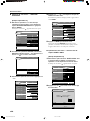
6 Subtitle Zoom
This mode is the most appropriate for showing subtitled letter
box format video software. There are more detailed settings for
this mode, which can be adjusted in the Subtitle Zoom area of
the 2 <SIGNAL> section of the menu. Refer to page 24 for
details.
• Subtitle Area
Adjust the settings for subtitles.
• V Scroll
Adjust the position of the subtitles by moving the screen
vertically.
7 Through
This mode displays the signal as it is input with no enlargement
or reduction. The projected image size will vary according to
the resolution of the signal.
8 Through Squeeze
This mode expands the width of the input signal to display the
image in a 16:9 aspect. The projected image size will vary
according to the resolution of the signal.
[Representative examples]
Input signal type
Standard 4:3 image
Letter box
Squeeze
(Vista size)
Squeeze
(Cinemascope size)
HDTV
RGB PC
Input image Display aspect
Normal
Smart Zoom
Zoom
Subtitle Zoom
Squeeze
Through Squeeze
Squeeze
Normal
Normal
Projected image
SUBTITLE
104_DPX-1000(E)11-15 03.3.5, 6:13 PM14

E-15
BASIC OPERATION
English
Basic Operations
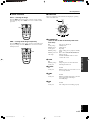
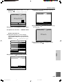
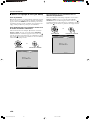
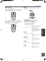
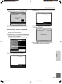
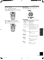
■ Other functions
STILL — freezing the image
Press the STILL button on the remote control to capture a frame
from a moving image. Press STILL once more to resume normal
projection.
HIDE — turning off the image temporarily
Press the HIDE button on the remote control to temporarily turn of
the projected image. Press the HIDE button once more to resume
normal projection.
■ Indicators
There are 5 indicators on the main unit that display the operating
status of the DPX-1000.
1 STANDBY/ON
(There is also an LED on the front panel of the
main unit.)
Off The power is turned off.
Steady orange Standby mode
Blinking green Startup mode
Steady green Operating
Blinking orange Lamp cooling prior to going into Standby
mode
Blinking red or red One of the LAMP/COVER/TEMP/FAN
and orange lights is also red.
Consult a YAMAHA dealer or service
center if this occurs.
2 LAMP
Off Normal
Blinking orange Lamp usage has exceeded 2000 hours.
Steady red The lamp has burnt out.
3 COVER
Off Normal
Steady red Either the lamp cover or the filter cover is
not correctly attached.
4 TEMP
Off Normal
Steady red Either the internal temperature of the unit
or the temperature of the lamp is
abnormally high.
5 FAN
Off Normal
Steady red The cooling fan is not working properly.
45
RESET
6
123
VIDEO
STILL HIDE
INPUT
ASPECT
LIGHT
BD4
S VIDEO
A
INPUT
MEMORY
DVI
STILL
45
RESET
6
123
VIDEO
STILL HIDE
INPUT
ASPECT
LIGHT
BD4
S VIDEO
A
INPUT
MEMORY
DVI
HIDE
STANDBY
/
ON
SETTING
LAMP COVER TEMP FAN
PATTERN
ESCAPE
MENU
INPUT
ASPECT
1
34
5
2
104_DPX-1000(E)11-15 03.3.5, 6:13 PM15

E-16
hg
hg
hg
hg
hg
hg
hg
hg
hg
hg
hg
hg
hg
hg hg hg hg hg
hg hg hg hg
hg hg hg
hg hg
hg
hg hg
hg hg
hg hg
hg hg
hg hg
hg hg
hg hg
hg hg
hg hg
hg hg
hg hg
hg hg
hg hg
hg hg hg
Move Menu Window
Image
Black Level
Off L ML MH H
A B C D E
Memory 1 VIDEO
0
White Level 0
Gamma Trim
Hue 0
Saturation 100
Color Temp.
Sharpness Type
Sharpness Gain
Level Adjustment
Iris
Color Balance
16
Signal Initial Setup
6000K
+
–
0.000uv
Standard
hgStandard Cinema
Location
Keystone
Remote Control Sensor
Remote Control ID
Lens Adjustment Lock
White Boost
Economy Mode
Menu Color
Message
Trigger Out
Baud Rate
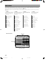
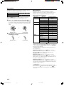
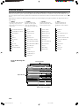
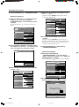
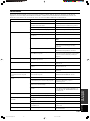
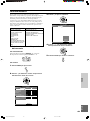
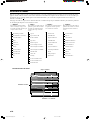
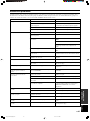
Menu structure
1 <IMAGE>
These menu items make adjustments
to the projection image. The menu
details will vary depending on the
input signal type.
2 <SIGNAL>
These menu items set parameters for
the various input signals. The menu
details will vary depending on the
input signal type.
3 <INITIAL>
These menu items set the initial
parameters for a number of menu
items.
4 <SETUP>
These menu items set parameters
related to installation method,
remote control and so on.
Black Level (Brightness)
White Level (Contrast)
Gamma Trim
Hue
Saturation
Color Temp.
Sharpness Type
Sharpness Gain
Color Balance
Level Adjustment
Iris
Display Aspect
3D Y/C Separation
Noise Reduction
Video Type
Progressive Mode
Color Space Conversion
Setup Level (SDTV)
Setup Level (HDTV)
Signal Level
Sync Adjustment
Tracking
Horiz. Display Position
Vert. Display Position
Signal Status
Color System
INPUT A Signal
INPUT A Sync Type
INPUT B Signal
INPUT B Sync Type
DVI Signal
Auto Power Off
Auto Input Search
Display Language
Lamp Running Time
Reset
Menu Start Screen
Menu Item
Menu Group
Items with a submenu
It is necessary to set various properties on a variety of menus so that this unit can project in optimal condition. There are four menu groups,
each with a number of different menu items. Some of these items are not selectable for certain types of input signal, some have submenus
attached, and others have a three stage menu hierarchy. (Displayed with a
S
overleaf.)
Each menu group consists of the items below. Follow the procedures outlined to adjust the parameters in each menu to suit your viewing
requirements.
105_DPX-1000(E)16-21 03.3.5, 6:14 PM16

E-17
MENU
English
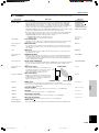
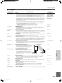
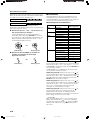
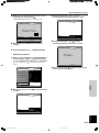
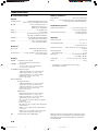
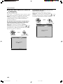
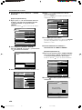
Menu Item
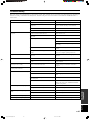
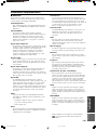
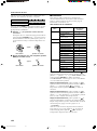
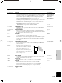
BLACK LEVEL
Adjusts the level of blackness in an image while maintaining peak white brightness. Increasing
the black level will increase the luminosity of dark scenes and clarify picture tone, however it
will also lower the contrast. Reducing the black level will increase the contrast in dark scenes
but will reduce the clarity of black tones.
WHITE LEVEL (*CONTRAST)
Increases the level of whiteness in an image without changing the luminosity of the darker parts
of the image. Increasing the white level will brighten the white areas of an image and increase
contrast, however it will also reduce the clarity of white within the image. Reducing the white
level will lower contrast.
(*BRIGHTNESS)
Controls the total brightness of an image. When set too high, the black portion of the image
becomes grayish and the white portion of the image tends to be saturated. When set too low, the
entire image becomes darker.
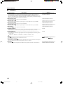
GAMMA TRIM
Adjusts the response of the color gradation and gray scale within the image. There are ten
patterns available, on two pages of five patterns each. Use the key to switch between the
pages, and select the appropriate pattern for the contents to be viewed.
HUE
Adjusts the hue of the image. Reducing this setting increases the amount of red in the image.
Increasing it will add blue to the image.
SATURATION
Adjusts color depth. Reducing the value of this setting lightens the color of the image, while
increasing it will increase the depth of color.
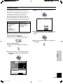
COLOR TEMP.
S
Adjusts the level of white in colors between red and blue, and between green and magenta. A
lower setting adds more red to the colors giving a more relaxed feel to the image, while a higher
setting adds more blue, resulting in “fresh” color tones. Also, increase the hUV to give more
green to the image, or reduce it to add more magenta.
Adjustment range
–100 to 0 to +100
–100 to 0 to +100
(*0.50 to 1.00 to 1.50)
–100 to 0 to +100
A/B/C/D/E
a/b/c/d/e
–100 to 0 to +100
0 to 100 to 200
5000K to 6000K
to 10000K
(COLOR TEMP.)
–0.020UV to ±0.000 to
+0.020UV (hUV)
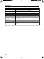
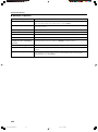
■ 1 <IMAGE> ........ You cannot adjust these settings without an input signal.
Input signal
Video/Component,
RGB TV
Video/Component,
RGB TV, *RGB PC
*RGB PC
Video/Component,
RGB TV, RGB PC
Video/Component,
RGB TV
Video/Component,
RGB TV
Video/Component,
RGB TV, RGB PC
+
–
COLOR TEMP. ADJUSTMENT
Color temp. adjustment
Menu structure
BLACK LEVEL
White White
Output image
Black
BlackWhite White
Input signal Input signal
WHITE LEVEL
(*CONTRAST)
White
Black White
Input signal
(*BRIGHTNESS)
hUV
105_DPX-1000(E)16-21 03.3.5, 6:14 PM17
Sidan laddas...
Sidan laddas...
Sidan laddas...
Sidan laddas...
Sidan laddas...
Sidan laddas...
Sidan laddas...
Sidan laddas...
Sidan laddas...
Sidan laddas...
Sidan laddas...
Sidan laddas...
Sidan laddas...
Sidan laddas...
Sidan laddas...
Sidan laddas...
Sidan laddas...
Sidan laddas...
Sidan laddas...
Sidan laddas...
Sidan laddas...
Sidan laddas...
Sidan laddas...
Sidan laddas...
Sidan laddas...
Sidan laddas...
Sidan laddas...
Sidan laddas...
Sidan laddas...
Sidan laddas...
Sidan laddas...
Sidan laddas...
Sidan laddas...
Sidan laddas...
Sidan laddas...
Sidan laddas...
Sidan laddas...
Sidan laddas...
Sidan laddas...
Sidan laddas...
Sidan laddas...
Sidan laddas...
Sidan laddas...
Sidan laddas...
Sidan laddas...
Sidan laddas...
Sidan laddas...
Sidan laddas...
Sidan laddas...
Sidan laddas...
Sidan laddas...
Sidan laddas...
Sidan laddas...
Sidan laddas...
Sidan laddas...
Sidan laddas...
Sidan laddas...
Sidan laddas...
Sidan laddas...
Sidan laddas...
Sidan laddas...
Sidan laddas...
Sidan laddas...
Sidan laddas...
Sidan laddas...
Sidan laddas...
Sidan laddas...
Sidan laddas...
Sidan laddas...
Sidan laddas...
Sidan laddas...
Sidan laddas...
Sidan laddas...
Sidan laddas...
Sidan laddas...
Sidan laddas...
Sidan laddas...
Sidan laddas...
Sidan laddas...
Sidan laddas...
Sidan laddas...
Sidan laddas...
Sidan laddas...
Sidan laddas...
Sidan laddas...
Sidan laddas...
Sidan laddas...
Sidan laddas...
Sidan laddas...
Sidan laddas...
Sidan laddas...
Sidan laddas...
Sidan laddas...
Sidan laddas...
Sidan laddas...
Sidan laddas...
Sidan laddas...
Sidan laddas...
Sidan laddas...
Sidan laddas...
Sidan laddas...
Sidan laddas...
Sidan laddas...
Sidan laddas...
Sidan laddas...
Sidan laddas...
Sidan laddas...
Sidan laddas...
Sidan laddas...
Sidan laddas...
Sidan laddas...
Sidan laddas...
Sidan laddas...
Sidan laddas...
Sidan laddas...
Sidan laddas...
Sidan laddas...
Sidan laddas...
Sidan laddas...
Sidan laddas...
Sidan laddas...
Sidan laddas...
Sidan laddas...
Sidan laddas...
Sidan laddas...
Sidan laddas...
Sidan laddas...
Sidan laddas...
Sidan laddas...
Sidan laddas...
Sidan laddas...
Sidan laddas...
Sidan laddas...
Sidan laddas...
Sidan laddas...
Sidan laddas...
Sidan laddas...
Sidan laddas...
Sidan laddas...
Sidan laddas...
Sidan laddas...
Sidan laddas...
Sidan laddas...
Sidan laddas...
Sidan laddas...
Sidan laddas...
Sidan laddas...
Sidan laddas...
Sidan laddas...
Sidan laddas...
Sidan laddas...
Sidan laddas...
Sidan laddas...
Sidan laddas...
Sidan laddas...
Sidan laddas...
Sidan laddas...
Sidan laddas...
Sidan laddas...
Sidan laddas...
Sidan laddas...
Sidan laddas...
Sidan laddas...
Sidan laddas...
Sidan laddas...
Sidan laddas...
Sidan laddas...
Sidan laddas...
Sidan laddas...
Sidan laddas...
Sidan laddas...
Sidan laddas...
Sidan laddas...
Sidan laddas...
Sidan laddas...
Sidan laddas...
Sidan laddas...
Sidan laddas...
Sidan laddas...
Sidan laddas...
Sidan laddas...
Sidan laddas...
Sidan laddas...
Sidan laddas...
Sidan laddas...
Sidan laddas...
Sidan laddas...
-
 1
1
-
 2
2
-
 3
3
-
 4
4
-
 5
5
-
 6
6
-
 7
7
-
 8
8
-
 9
9
-
 10
10
-
 11
11
-
 12
12
-
 13
13
-
 14
14
-
 15
15
-
 16
16
-
 17
17
-
 18
18
-
 19
19
-
 20
20
-
 21
21
-
 22
22
-
 23
23
-
 24
24
-
 25
25
-
 26
26
-
 27
27
-
 28
28
-
 29
29
-
 30
30
-
 31
31
-
 32
32
-
 33
33
-
 34
34
-
 35
35
-
 36
36
-
 37
37
-
 38
38
-
 39
39
-
 40
40
-
 41
41
-
 42
42
-
 43
43
-
 44
44
-
 45
45
-
 46
46
-
 47
47
-
 48
48
-
 49
49
-
 50
50
-
 51
51
-
 52
52
-
 53
53
-
 54
54
-
 55
55
-
 56
56
-
 57
57
-
 58
58
-
 59
59
-
 60
60
-
 61
61
-
 62
62
-
 63
63
-
 64
64
-
 65
65
-
 66
66
-
 67
67
-
 68
68
-
 69
69
-
 70
70
-
 71
71
-
 72
72
-
 73
73
-
 74
74
-
 75
75
-
 76
76
-
 77
77
-
 78
78
-
 79
79
-
 80
80
-
 81
81
-
 82
82
-
 83
83
-
 84
84
-
 85
85
-
 86
86
-
 87
87
-
 88
88
-
 89
89
-
 90
90
-
 91
91
-
 92
92
-
 93
93
-
 94
94
-
 95
95
-
 96
96
-
 97
97
-
 98
98
-
 99
99
-
 100
100
-
 101
101
-
 102
102
-
 103
103
-
 104
104
-
 105
105
-
 106
106
-
 107
107
-
 108
108
-
 109
109
-
 110
110
-
 111
111
-
 112
112
-
 113
113
-
 114
114
-
 115
115
-
 116
116
-
 117
117
-
 118
118
-
 119
119
-
 120
120
-
 121
121
-
 122
122
-
 123
123
-
 124
124
-
 125
125
-
 126
126
-
 127
127
-
 128
128
-
 129
129
-
 130
130
-
 131
131
-
 132
132
-
 133
133
-
 134
134
-
 135
135
-
 136
136
-
 137
137
-
 138
138
-
 139
139
-
 140
140
-
 141
141
-
 142
142
-
 143
143
-
 144
144
-
 145
145
-
 146
146
-
 147
147
-
 148
148
-
 149
149
-
 150
150
-
 151
151
-
 152
152
-
 153
153
-
 154
154
-
 155
155
-
 156
156
-
 157
157
-
 158
158
-
 159
159
-
 160
160
-
 161
161
-
 162
162
-
 163
163
-
 164
164
-
 165
165
-
 166
166
-
 167
167
-
 168
168
-
 169
169
-
 170
170
-
 171
171
-
 172
172
-
 173
173
-
 174
174
-
 175
175
-
 176
176
-
 177
177
-
 178
178
-
 179
179
-
 180
180
-
 181
181
-
 182
182
-
 183
183
-
 184
184
-
 185
185
-
 186
186
-
 187
187
-
 188
188
-
 189
189
-
 190
190
-
 191
191
-
 192
192
-
 193
193
-
 194
194
-
 195
195
-
 196
196
-
 197
197
-
 198
198
-
 199
199
-
 200
200
-
 201
201
-
 202
202
-
 203
203
-
 204
204
-
 205
205
-
 206
206
-
 207
207


Yamaha DPX-1000 Bruksanvisning
- Kategori
- Dataprojektorer
- Typ
- Bruksanvisning
på andra språk
- italiano: Yamaha DPX-1000 Manuale del proprietario
- español: Yamaha DPX-1000 El manual del propietario
- Deutsch: Yamaha DPX-1000 Bedienungsanleitung
- français: Yamaha DPX-1000 Le manuel du propriétaire
- Türkçe: Yamaha DPX-1000 El kitabı
- English: Yamaha DPX-1000 Owner's manual
- dansk: Yamaha DPX-1000 Brugervejledning
- suomi: Yamaha DPX-1000 Omistajan opas
- Nederlands: Yamaha DPX-1000 de handleiding
- română: Yamaha DPX-1000 Manualul proprietarului
Relaterade papper
Andra dokument
-
Celexon Écran de projection de sol motorisé HomeCinema à Haut Contraste 265 x 149 cm, 120" Bruksanvisning
-
-
iiyama PLG2773HS-B1 Datablad
-
BenQ ScreenBar Halo Användarmanual
-
-
-
-
-
König KN-AVSPLIT20 Bruksanvisning
-
AVENTICS Flow rate sensor, series AF2 Bruksanvisningar