Victron BMV-700 & BMV-700H Användarmanual
- Typ
- Användarmanual

Manual
EN
Handleiding
NL
Manuel
FR
Anleitung
DE
Manual
ES
Användarhandbok
SE
Appendix
Appendix
Battery Monitor
BMV-700
BMV-700H
BMV-702
BMV-712 Smart


1
NL FR DE ES SE IT PT
EN NL FR DE ES SE Appendix
1 QUICK START GUIDE
1.1 Battery capacity
1.2 Auxiliary input (BMV-702 and BMV-712 Smart only)
1.3 Important combined button functions
2 NORMAL OPERATING MODE
2.1 Read-out overview
2.2 Synchronising the BMV
2.3 Common problems
3 FEATURES AND FUNCTIONALITY
3.1 Features of the three BMV models
3.2 Why should I monitor my battery?
3.3 How does the BMV work?
3.3.1 About battery capacity and the rate of discharge
3.3.2 About charge efficiency (CEF)
3.4 Several battery state of charge display options
3.5 History data
3.6 Use of alternative shunts
3.7 Automatic detection of nominal system voltage
3.8 Alarm, buzzer and relay
3.9 Interface options
3.9.1 PC Software
3.9.2 Large display and remote monitoring
3.9.3 Custom integration (programming required)
3.10 Additional functionality of the BMV-702 and BMV-712 Smart
3.10.1 Auxiliary battery monitoring
3.10.2 Battery temperature monitoring
3.10.3 Midpoint voltage monitoring
3.11 Additional functionality of the BMV-712 Smart
3.11.1 Automatic cycling through status-items
3.11.2 Turning Bluetooth On/Off
4 FULL SETUP DETAILS
4.1 Using the menus
4.2 Function overview
4.2.1 Battery settings
4.2.2 Relay settings
4.2.3 Alarm-Buzzer settings
4.2.4 Display settings
4.2.5 Miscellaneous
4.3 History data
5 MORE ABOUT PEUKERT’S FORMULA AND MIDPOINT MONITORING
6 LITHIUM IRON PHOSPHATE BATTERIES (LiFePO4)
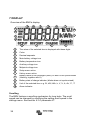
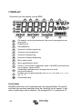
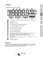
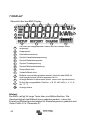
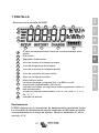
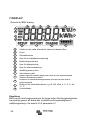
7 DISPLAY
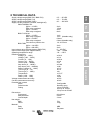
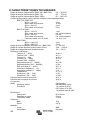
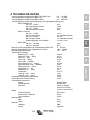
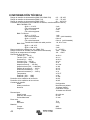
8 TECHNICAL DATA

2
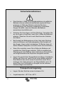
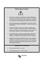
Safety Precautions
• Working in the vicinity of a lead acid battery is
dangerous. Batteries can generate explosive gases
during operation. Never smoke or allow a spark or flame
in the vicinity of a battery. Provide sufficient ventilation
around the battery.
• Wear eye and clothing protection. Avoid touching eyes
while working near batteries. Wash your hands when
done.
• If battery acid contacts skin or clothing, wash them
immediately with soap and water. If acid enters an eye,
immediately flood the eye with running cold water for at
least 15 minutes and get medical attention immediately.
• Be careful when using metal tools in the vicinity of
batteries. Dropping a metal tool onto a battery might
cause a short circuit and possibly an explosion.
• Remove personal metal items such as rings, bracelets,
necklaces, and watches when working with a battery. A
battery can produce a short circuit current high enough
to melt objects such as rings, causing severe burns.
Transport and storage
• Store the product in a dry environment.
• Storage temperature: -40°C to +60°C

3
NL FR DE ES SE IT PT
EN NL FR DE ES SE Appendix
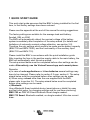
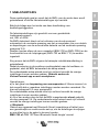
1 QUICK START GUIDE
This quick start guide assumes that the BMV is being installed for the first
time, or that factory settings have been restored.
Please see the appendix at the end of this manual for wiring suggestions.
The factory settings are suitable for the average lead acid battery:
flooded, GEL or AGM.
The BMV will automatically detect the nominal voltage of the battery
system immediately after completion of the setup wizard (for details and
limitations of automatic nominal voltage detection, see section 3.8).
Therefore the only settings which need to be made are the battery capacity
(BMV-700 and BMV-700H), and the functionality of the auxiliary input
(BMV-702 and BMV-712).
Please install the BMV in accordance with the quick installation guide.
After inserting the fuse in the positive supply cable to the main battery, the
BMV will automatically start the setup wizard.
The setup wizard below must be completed before other settings can be
made. Alternatively, use the VictronConnect app and a smart phone.
Remarks:
a) In case of solar applications or Li-ion batteries several settings may
have to be changed. Please refer to section 2.3 resp. section 6. The setup
wizard below must be completed before other settings can be made.
b) When using a shunt other than the one supplied with the BMV,
please refer to section 3.6. The setup wizard below must be completed
before other settings can be made.
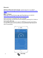
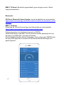
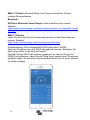
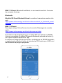
c) Bluetooth
Use a Bluetooth Smart enabled device (smart phone or tablet) for easy
and fast initial setup, for changing settings and for real time monitoring.
BMV-700 or -702: VE.Direct Bluetooth Smart dongle needed.
BMV-712 Smart: Bluetooth enabled, no dongle needed. Ultra low current
draw.

4
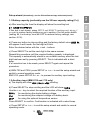
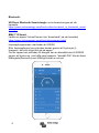
Bluetooth:
VE.Direct Bluetooth Smart dongle: see the manual on our website
https://www.victronenergy.com/live/ve.direct:ve.direct_to_bluetooth_smart_
dongle
BMV-712 Smart:
Download the VictronConnect app (see Downloads on our website)
https://www.victronenergy.com/live/victronconnect:start
Pairing procedure: the default PIN code is 000000
After connecting, the PIN code can be changed by pressing the (i) button in
the top right of the app.
If the dongle PIN code is lost, reset it to 000000 by pressing and holding
the clear PIN button until the solid blue colored Bluetooth light flashes off
and on momentarily.

5
NL FR DE ES SE IT PT
EN NL FR DE ES SE Appendix
Setup wizard (alternatively, use the VictronConnect app and smart phone):
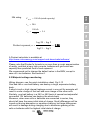
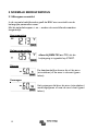
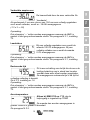
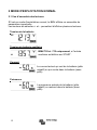
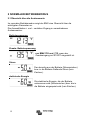
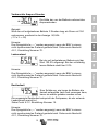
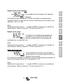
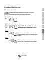
1.1 Battery capacity (preferably use the 20 hour capacity rating (C
20))
a) After inserting the fuse the display will show the scrolling text
If this text is not shown, press SETUP and SELECT simultaneously during 3
seconds to restore factory settings or go to section 4 for full setup details
(setting 64, Lock setup, must be OFF to restore factory settings, see
section 4.2.5).
b) Press any button to stop scrolling and the factory default value
will appear in edit mode: the first digit will blink.
Enter the desired value with the + and – buttons.
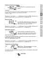
c) Press SELECT to set the next digit in the same manner.
Repeat this procedure until the required battery capacity is displayed.
The capacity is automatically stored in non-volatile memory when the last
digit has been set by pressing SELECT. This is indicated with a short
beep.
If a correction has to be made, press SELECT again and repeat the
procedure.
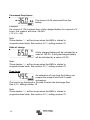
d) BMV-700 and 700H: press SETUP or + or – to end the setup wizard and
switch to normal operating mode.
BMV-702: press SETUP or + or – to proceed to auxiliary input setting.
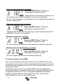
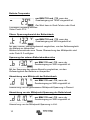
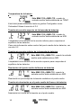
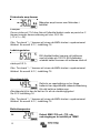
1.2 Auxiliary input (BMV-702 and -712 only)
a) The display will show
scrolling.
b) Press SELECT to stop scrolling and the LCD will show:
Use the + or – key to select the required function of the auxiliary input:
for monitoring the starter battery voltage.
for monitoring the midpoint voltage of a battery bank.
for using the optional temperature sensor
Press SELECT to confirm. Confirmation is indicated with a short beep.
c) Press SETUP or + or – to end the setup wizard and switch to normal
operating mode.

6
The BMV is now ready for use.
When powered up for the first time, the BMV will by default display 100%
state of charge. See section 4.2.1, setting 70 to change this this
behaviour.
When in normal mode the backlight of the BMV switches off after no key
has been pressed for 60 seconds. Press any key to restore backlight.
The cable with integrated temperature sensor has to be purchased
separately (part no: ASS000100000). This temperature sensor is not
interchangeable with other Victron temperature sensors, as used with
Multis/Quattros or battery chargers.
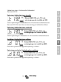
1.3 Important combined button functions
(see also section 4.1: using the menus)
a) Restore factory settings
Press and hold SETUP and SELECT simultaneously for 3 seconds
b) Manual synchronisation
Press and hold the up and down buttons simultaneously for 3 seconds
c) Silence audible alarm
An alarm is acknowledged when any button is pressed. However, the
alarm icon is displayed as long as the alarm condition remains.
1.4 Realtime data displayed on a smartphone
With the VE.Direct Bluetooth Smart dongle realtime data and alarms can
be displayed on Apple and Android smartphones, tablets and other
devices.
Note:
A VE.Direct Bluetooth Smart dongle is not required for BMV-712, since it
has Bluetooth built-in.

7
NL FR DE ES SE IT PT
EN NL FR DE ES SE Appendix
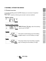
2 NORMAL OPERATING MODE
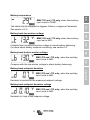
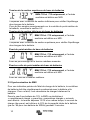
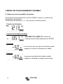
2.1 Readout overview
In normal operating mode the BMV displays an overview of important
parameters.
The + and – selection buttons give access to various readouts:
Battery voltage
Auxiliary battery voltage
BMV-702 and -712 only, when the auxiliary
input is set to START.
Current
The actual current flowing out of the battery
(negative sign) or into the battery (no sign).
Power
The power drawn from the battery (negative
sign) or flowing into the battery (no sign).

8
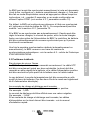
Consumed Amp-hours
The amount of Ah consumed from the
battery
Example:
If a current of 12A is drawn from a fully charged battery for a period of 3
hours, this readout will show -36.0Ah.
(-12 x 3 = -36)
Note:
Three dashes ‘---’ will be shown when the BMV is started in
unsynchronised state. See section 4.2.1, setting number 70.
State of charge
A fully charged battery will be indicated by a
value of 100.0%. A fully discharged battery
will be indicated by a value of 0.0%.
Note:
Three dashes ‘---’ will be shown when the BMV is started in
unsynchronised state. See section 4.2.1, setting number 70.
Time-to-go
An estimation of how long the battery can
support the present load until it needs
recharging.
The time-to-go displayed is the time to reach the discharge floor.
See 4.2.2, setting number 16.
Note:
Three dashes ‘---’ will be shown when the BMV is started in
unsynchronised state. See section 4.2.1, setting number 70.

9
NL FR DE ES SE IT PT
EN NL FR DE ES SE Appendix
Battery temperature
BMV-702 and -712 only, when the auxiliary
input is set to TEMP.
The value can be displayed in degrees Celsius or degrees Fahrenheit.
See section 4.2.5.
Battery bank top section voltage
BMV-702 and -712 only, when the auxiliary
input set to MID.
Compare with the bottom section voltage to check battery balancing.
For more about battery midpoint monitoring, see section 5.2.
Battery bank bottom section voltage
BMV-702 and -712 only, when the auxiliary
input is set to MID.
Compare with the top section voltage to check battery balancing.
Battery bank midpoint deviation
BMV-702 and -712 only, when the auxiliary
input is set to MID.
Deviation in percent of the measured midpoint voltage.
Battery bank midpoint deviation voltage
BMV-702 and -712 only, when the auxiliary
input is set to MID.
Deviation in Volts of the midpoint voltage.

10
2.2 Synchronising the BMV
For a reliable readout, the state of charge as displayed by the battery
monitor has to be synchronised regularly with the true state of charge of
the battery. This is accomplished by fully charging the battery.
In case of a 12V battery, the BMV resets to ‘fully charged’ when the
following ‘charged parameters’ are met: the voltage exceeds 13.2V and
simultaneously the (tail-) charge current is less than 4.0% of the total
battery capacity (e.g. 8A for a 200Ah battery) during 3 minutes.
The BMV can also be synchronised (i.e. set to ‘battery fully charged’)
manually if required. This can be achieved in normal operating mode by
holding the + and – buttons simultaneously for 3 seconds, or in setup
mode by using the SYNC option (see section 4.2.1, setting number 10).
By default, the BMV is configured to start-up in a synchronised state and
will indicate a state of charge of 100%. This behaviour can be changed:
see section 4.2.1, setting number 70.
If the BMV does not synchronise automatically, the charged voltage, tail
current, and/or charged time may need adjustment. When the voltage
supply to the BMV has been interrupted, the battery monitor must be
resynchronised before it can operate correctly.
After having synchronised for the first time (automatically or manually),
the BMV keeps track of the number of automatic synchronisations: see
section 4.3, history item SYNCHRONISATIONS.

11
NL FR DE ES SE IT PT
EN NL FR DE ES SE Appendix
2.3 Common problems
No signs of life on the display
Probably the BMV is not properly wired. The UTP cable should be
properly inserted at both ends, the shunt must be connected to the minus
pole of the battery, and the positive supply cable should be connected to
the plus pole of the battery with the fuse inserted.
The temperature sensor (when used) must be connected to the positive
pole of the battery bank (one of the two wires of the sensor doubles as
the power supply wire).
Charge and discharge current are inverted
Charge current should be shown as a positive value.
For example: 1.45A.
Discharge current should be shown as a negative value.
For example: -1.45A.
If charge and discharge current are inverted, the power cables on the
shunt must be swapped: see the quick installation guide.
The BMV does not synchronise automatically
One possibility is that the battery never reaches the fully charged state.
The other possibility is that the charged voltage setting should be lowered
and/or the tail current setting should be increased.
See section 4.2.1.
The BMV synchronises too early
In solar systems or other applications with fluctuating charge currents, the
following measures can be taken to reduce the probability for the BMV to
reset prematurely to 100% state of charge:
a) Increase the “charged” voltage to only slightly below the absorption charge voltage (for
example: 14.2V in case of 14.4V absorption voltage).
b) Increase the “charged” detection time and/or decrease the tail current to prevent an
early reset due to to passing clouds.
See section 4.2.1 for set up instructions.
Sync and battery icon are blinking
This means the battery is not synchronised. Charge the batteries and the
BMV should sync automatically. If that doesn't work, review the sync
settings. Or, if you know the battery is fully charged but don't want to wait
until the BMV synchronises: press and hold the up and down button
simultaneously, until you hear a beep.
See section 4.2.1.

12
3 FEATURES AND FUNCTIONALITY
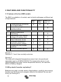
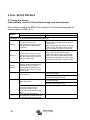
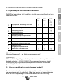
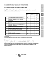
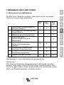
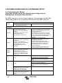
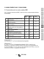
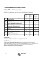
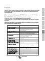
3.1 Features of the four BMV models
The BMV is available in 4 models, each of which addresses a different set
of requirements.
BMV-
700
BMV-
700H
BMV-702
and 712
1
Comprehensive monitoring
of a single battery
•
•
•
2
Basic monitoring of an
auxiliary battery
•
3
Battery temperature
monitoring
•
4
Monitoring of the midpoint
voltage of a battery bank
•
5 Use of alternate shunts
•
•
•
6
Automatic detection of
nominal system voltage
•
•
•
7
Suitable for high voltage
systems
•
8 Several interface options
•
•
•
Remark 1:
Features 2, 3 and 4 are mutually exclusive.
Remark 2:
The cable with integrated temperature sensor has to be purchased
separately (part no: ASS000100000).This temperature sensor is not
interchangeable with other Victron temperature sensors, as used with
Multis or battery chargers.
3.2 Why should I monitor my battery?
Batteries are used in a wide variety of applications, mostly to store energy
for later use. But how much energy is stored in the battery? No one can
tell by just looking at it.

13
NL FR DE ES SE IT PT
EN NL FR DE ES SE Appendix
The service life of batteries depends on many factors. Battery life may be
shortened by undercharging, overcharging, excessively deep discharges,
excessive charge or discharge current, and high ambient temperature. By
monitoring the battery with an advanced battery monitor, important
feedback is given to the user so that remedial measures can be taken
when necessary. Doing this, which extends battery life, the BMV will
quickly pay for itself.
3.3 How does the BMV work?
The main function of the BMV is to follow and indicate the state of charge
of a battery, in particular to prevent unexpected total discharge.
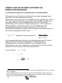
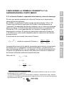
The BMV continuously measures the current flow in and out of the
battery. Integration of this current over time (which, if the current is a fixed
amount of Amps, boils down to multiplying current and time) gives the net
amount of Ah added or removed.
For example: a discharge current of 10A during 2 hours will take 10 x 2 =
20Ah from the battery.
To complicate matters, the effective capacity of a battery depends on the
rate of discharge and, to a lesser extent, on temperature.
And to make things even more complicated: when charging a battery
more Ah has to be ‘pumped’ into the battery than can be retrieved during
the next discharge. In other words: the charge efficiency is less than
100%.
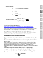
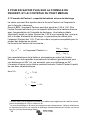
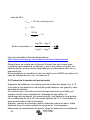
3.3.1 About battery capacity and the rate of discharge
The capacity of a battery is rated in ampere-hours (Ah). For example, a
lead acid battery that can deliver a current of 5A during 20 hours is rated
at C
20 = 100Ah (5 x 20 = 100).
When the same 100Ah battery is discharged completely in two hours, it
may only give C
2 = 56Ah (because of the higher rate of discharge).
The BMV takes this phenomenon into account with Peukert’s formula: see
section 5.1.

14
3.3.2 About charge efficiency (CEF)
The charge efficiency of a lead acid battery is almost 100% as long as no
gas generation takes place. Gassing means that part of the charge
current is not transformed into chemical energy, which is stored in the
plates of the battery, but is used to decompose water into oxygen and
hydrogen gas (highly explosive!). The ‘Amp-hours’ stored in the plates
can be retrieved during the next discharge, whereas the ‘Amp-hours’
used to decompose water are lost.
Gassing can easily be observed in flooded batteries. Please note that the
‘oxygen only’ end of charge phase of sealed (VRLA) gel and AGM
batteries also results in a reduced charge efficiency.
A charge efficiency of 95% means that 10Ah must be transferred to the
battery to get 9.5Ah actually stored in the battery. The charge efficiency of
a battery depends on battery type, age and usage.
The BMV takes this phenomenon into account with the charge efficiency
factor: see section 4.2.2, setting number 06.
3.4 Several battery state of charge display options
The BMV can display both the Amp-hours removed (‘consumed Amp-
hours’ readout, compensated for charge efficiency only) and the actual
state of charge in percent (‘state of charge’ readout, compensated for
charge efficiency and Peukert efficiency). Reading the state of charge is
the best way to monitor the battery.
The BMV also estimates how long the battery can support the present
load: the ‘time-to-go’ readout. This is the actual time left until the battery is
discharged to the discharge floor. The factory discharge floor setting is
50% (see 4.2.2, setting number 16).
If the load is fluctuating heavily it is best not to rely on this reading too
much since it is a momentary readout and must be used as a guideline
only. We always encourage the use of the state of charge readout for
accurate battery monitoring. The battery state of charge indicator (see
chapter 7 “Display”) scales between the configured discharge floor and
100% state of charge and reflects the effective state of charge.
3.5 History data
The BMV stores events which can be used at a later date to evaluate
usage patterns and battery health.
Select the history data menu by pressing ENTER when in normal mode
(see section 4.3).

15
NL FR DE ES SE IT PT
EN NL FR DE ES SE Appendix
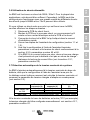
3.6 Use of alternative shunts
The BMV is supplied with a 500A / 50mV shunt. For most applications,
this should be suitable; however the BMV can be configured to work with
a wide range of different shunts. Shunts of up to 9999A, and/or 75mV can
be used.
When using a shunt other than the one supplied with the BMV, please
proceed as follows:
1. Unscrew the PCB from the supplied shunt.
2. Mount the PCB on the new shunt, ensuring that there is good
electrical contact between the PCB and the shunt.
3. Connect the shunt and BMV as shown in the quick installation
guide.
4. Follow the Setup wizard (section 1.1 and 1.2).
5. After completion of the Setup wizard, set the proper shunt
current and shunt voltage according to section 4.2.5, setting
number 65 and 66.
6. If the BMV reads a non-zero current even when there is no load
and the battery is not being charged: calibrate the zero current
reading (see section 4.2.1, setting number 09).
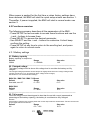
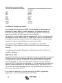
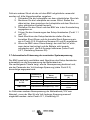
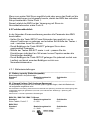
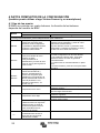
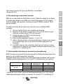
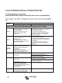
3.7 Automatic detection of nominal system voltage
The BMV will automatically adjust itself to the nominal voltage of the
battery bank, immediately after completion of the setup wizard.
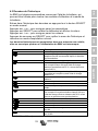
The following table shows how the nominal voltage is determined, and
how the charged voltage parameter (see section 2.2) is adjusted as a
result.
Measured
voltage (V)
Assumed nominal
voltage (V)
Charged voltage
(V)
BMV-700 & 702 &
712
< 18
12
13.2
18 – 36
24
26.4
> 36
48
52.8
BMV-700H
Default nominal voltage: 144V
Default: 158.4V
In case of another nominal battery bank voltage (32V for example), the
charged voltage must be set manually: see section 4.2.1, setting 02.

16
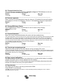
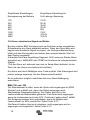
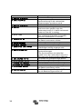
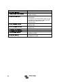
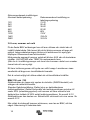
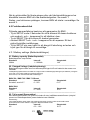
Recommended settings:
Nominal battery voltage Recommended Charged Voltage setting
12V 13.2V
24V 26.4V
36V 39.6V
48V 52.8V
60V 66V
120V 132V
144V 158.4V
288V 316.8V
3.8 Alarm, buzzer and relay:
On most of the BMV’s readings an alarm can be triggered when the value
reaches a set threshold. When the alarm becomes active the buzzer
starts to beep, the backlight flashes and the alarm icon is visible in the
display along with the current value.
The corresponding segment will also flash. AUX when a starter alarm
occurs. MAIN, MID or TEMP for the corresponding alarm.
(When in the setup menu and an alarm occurs, the value causing the
alarm will not be visible.)
An alarm is acknowledged when a button is pressed. However, the alarm
icon is displayed as long as the alarm condition remains.
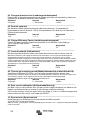
It is also possible to trigger the relay when an alarm condition occurs.
BMV-700 and -702
The relay contact is open when the coil is de-energised (NO contact), and
will close when the relay is energised.
Factory default setting: the relay is controlled by the state of charge of the
battery bank. The relay will be energised when the state of charge
decreases to less than 50% (the ‘discharge floor’), and will be de-
energised when the battery has been recharged to 90% state of charge.
See section 4.2.2.
The relay function can be inverted: de-energised becomes energised and
vice versa. See section 4.2.2.
When the relay is energised, the current drawn by the BMV will increase
slightly: see technical data.

17
NL FR DE ES SE IT PT
EN NL FR DE ES SE Appendix
BMV-712 Smart
The BMV-712 has been designed to minimize power consumption.
The alarm relay therefore is a bistable relay, and the current draw remains
low whatever the position of the relay.
3.9 Interface options
3.9.1 PC Software
Connect the BMV to the computer with the VE.Direct to USB interface
cable (ASS030530000) and download the appropriate software.
https://www.victronenergy.com/live/victronconnect:start
3.9.2 Large display and remote monitoring
The Color Control GX, a display featuring a 4.3” colour display, provides
intuitive control and monitoring for all products connected to it. The list of
Victron products that can be connected is endless: Inverters, Multis,
Quattros, MPPT solar chargers, BMV, Skylla-i, Lynx Ion and more. The
BMV can be connected to the Color Control GX with a VE.Direct cable. It
is also possible to connect it with the VE.Direct to USB interface. Besides
monitoring and controlling locally with the Color Control GX, the
information is also forwarded to our free remote monitoring website: the
VRM Online Portal.
For more information, see the Color Control GX
documentation on our website.
3.9.3 Custom integration (programming required)
The VE.Direct communications port can be used to read data and change
settings. The VE.Direct protocol is extremely simple to implement.
Transmitting data to the BMV is not necessary for simple applications: the
BMV automatically sends all readings every second. All the details are
explained in this document:
https://www.victronenergy.com/upload/documents/Whitepaper-Data-
communication-with-Victron-Energy-products_EN.pdf

18
3.10 Additional functionality of the BMV-702 and -712
In addition to the comprehensive monitoring of the main battery system,
the BMV-702 and -712 have a second monitoring input. This secondary
input has three configurable options, described below.
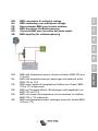
3.10.1 Auxiliary battery monitoring
Wiring diagram: see the quick installation guide. Fig 3
This configuration provides basic monitoring of a second battery,
displaying its voltage. This is useful for systems with a separate starter
battery.
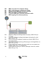
3.10.2 Battery temperature monitoring
Wiring diagram: see the quick installation guide. Fig 4
The cable with integrated temperature sensor has to be purchased
separately (part no: ASS000100000). This temperature sensor is not
interchangeable with other Victron temperature sensors, as provided with
Multis or battery chargers. The temperature sensor must be connected to
the positive pole of the battery bank (one of the two wires of the sensor
doubles as the power supply wire).
The temperature can be displayed in degrees Celsius or degrees
Fahrenheit, see section 4.2.5, setting number 67.
The temperature measurement can also be used to adjust battery
capacity to temperature, see section 4.2.5, setting number 68.
The available battery capacity decreases with temperature.
Typically, the reduction, compared to the capacity at 20°C, is 18% at 0°C
and 40% at -20°C.
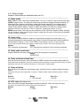
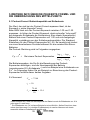
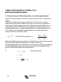
3.10.3 Midpoint voltage monitoring
Wiring diagram: see the quick installation guide. Fig 5 - 12
One bad cell or one bad battery can destroy a large, expensive battery
bank.
A short circuit or high internal leakage current in one cell for example will
result in under charge of that cell and over charge of the other cells.
Similarly, one bad battery in a 24V or 48V bank of several series/parallel
connected 12V batteries can destroy the whole bank.
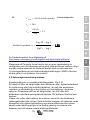
Moreover, when cells or batteries are connected in series, they should all
have the same initial state of charge. Small differences will be ironed out
during absorption or equalise charging, but large differences will result in
damage during charging due to excessive gassing of the cells or batteries
with the highest initial state of charge.
Sidan laddas...
Sidan laddas...
Sidan laddas...
Sidan laddas...
Sidan laddas...
Sidan laddas...
Sidan laddas...
Sidan laddas...
Sidan laddas...
Sidan laddas...
Sidan laddas...
Sidan laddas...
Sidan laddas...
Sidan laddas...
Sidan laddas...
Sidan laddas...
Sidan laddas...
Sidan laddas...
Sidan laddas...
Sidan laddas...
Sidan laddas...
Sidan laddas...
Sidan laddas...
Sidan laddas...
Sidan laddas...
Sidan laddas...
Sidan laddas...
Sidan laddas...
Sidan laddas...
Sidan laddas...
Sidan laddas...
Sidan laddas...
Sidan laddas...
Sidan laddas...
Sidan laddas...
Sidan laddas...
Sidan laddas...
Sidan laddas...
Sidan laddas...
Sidan laddas...
Sidan laddas...
Sidan laddas...
Sidan laddas...
Sidan laddas...
Sidan laddas...
Sidan laddas...
Sidan laddas...
Sidan laddas...
Sidan laddas...
Sidan laddas...
Sidan laddas...
Sidan laddas...
Sidan laddas...
Sidan laddas...
Sidan laddas...
Sidan laddas...
Sidan laddas...
Sidan laddas...
Sidan laddas...
Sidan laddas...
Sidan laddas...
Sidan laddas...
Sidan laddas...
Sidan laddas...
Sidan laddas...
Sidan laddas...
Sidan laddas...
Sidan laddas...
Sidan laddas...
Sidan laddas...
Sidan laddas...
Sidan laddas...
Sidan laddas...
Sidan laddas...
Sidan laddas...
Sidan laddas...
Sidan laddas...
Sidan laddas...
Sidan laddas...
Sidan laddas...
Sidan laddas...
Sidan laddas...
Sidan laddas...
Sidan laddas...
Sidan laddas...
Sidan laddas...
Sidan laddas...
Sidan laddas...
Sidan laddas...
Sidan laddas...
Sidan laddas...
Sidan laddas...
Sidan laddas...
Sidan laddas...
Sidan laddas...
Sidan laddas...
Sidan laddas...
Sidan laddas...
Sidan laddas...
Sidan laddas...
Sidan laddas...
Sidan laddas...
Sidan laddas...
Sidan laddas...
Sidan laddas...
Sidan laddas...
Sidan laddas...
Sidan laddas...
Sidan laddas...
Sidan laddas...
Sidan laddas...
Sidan laddas...
Sidan laddas...
Sidan laddas...
Sidan laddas...
Sidan laddas...
Sidan laddas...
Sidan laddas...
Sidan laddas...
Sidan laddas...
Sidan laddas...
Sidan laddas...
Sidan laddas...
Sidan laddas...
Sidan laddas...
Sidan laddas...
Sidan laddas...
Sidan laddas...
Sidan laddas...
Sidan laddas...
Sidan laddas...
Sidan laddas...
Sidan laddas...
Sidan laddas...
Sidan laddas...
Sidan laddas...
Sidan laddas...
Sidan laddas...
Sidan laddas...
Sidan laddas...
Sidan laddas...
Sidan laddas...
Sidan laddas...
Sidan laddas...
Sidan laddas...
Sidan laddas...
Sidan laddas...
Sidan laddas...
Sidan laddas...
Sidan laddas...
Sidan laddas...
Sidan laddas...
Sidan laddas...
Sidan laddas...
Sidan laddas...
Sidan laddas...
Sidan laddas...
Sidan laddas...
Sidan laddas...
Sidan laddas...
Sidan laddas...
Sidan laddas...
Sidan laddas...
Sidan laddas...
Sidan laddas...
Sidan laddas...
Sidan laddas...
Sidan laddas...
Sidan laddas...
Sidan laddas...
Sidan laddas...
Sidan laddas...
Sidan laddas...
Sidan laddas...
Sidan laddas...
Sidan laddas...
Sidan laddas...
Sidan laddas...
Sidan laddas...
Sidan laddas...
Sidan laddas...
Sidan laddas...
Sidan laddas...
Sidan laddas...
Sidan laddas...
Sidan laddas...
Sidan laddas...
Sidan laddas...
Sidan laddas...
Sidan laddas...
Sidan laddas...
Sidan laddas...
Sidan laddas...
Sidan laddas...
Sidan laddas...
Sidan laddas...
Sidan laddas...
Sidan laddas...
Sidan laddas...
Sidan laddas...
Sidan laddas...
Sidan laddas...
Sidan laddas...
Sidan laddas...
Sidan laddas...
Sidan laddas...
Sidan laddas...
Sidan laddas...
Sidan laddas...
Sidan laddas...
Sidan laddas...
Sidan laddas...
Sidan laddas...
Sidan laddas...
Sidan laddas...
Sidan laddas...
Sidan laddas...
Sidan laddas...
Sidan laddas...
Sidan laddas...
Sidan laddas...
Sidan laddas...
Sidan laddas...
Sidan laddas...
Sidan laddas...
Sidan laddas...
Sidan laddas...
Sidan laddas...
Sidan laddas...
Sidan laddas...
Sidan laddas...
Sidan laddas...
Sidan laddas...
Sidan laddas...
Sidan laddas...
-
 1
1
-
 2
2
-
 3
3
-
 4
4
-
 5
5
-
 6
6
-
 7
7
-
 8
8
-
 9
9
-
 10
10
-
 11
11
-
 12
12
-
 13
13
-
 14
14
-
 15
15
-
 16
16
-
 17
17
-
 18
18
-
 19
19
-
 20
20
-
 21
21
-
 22
22
-
 23
23
-
 24
24
-
 25
25
-
 26
26
-
 27
27
-
 28
28
-
 29
29
-
 30
30
-
 31
31
-
 32
32
-
 33
33
-
 34
34
-
 35
35
-
 36
36
-
 37
37
-
 38
38
-
 39
39
-
 40
40
-
 41
41
-
 42
42
-
 43
43
-
 44
44
-
 45
45
-
 46
46
-
 47
47
-
 48
48
-
 49
49
-
 50
50
-
 51
51
-
 52
52
-
 53
53
-
 54
54
-
 55
55
-
 56
56
-
 57
57
-
 58
58
-
 59
59
-
 60
60
-
 61
61
-
 62
62
-
 63
63
-
 64
64
-
 65
65
-
 66
66
-
 67
67
-
 68
68
-
 69
69
-
 70
70
-
 71
71
-
 72
72
-
 73
73
-
 74
74
-
 75
75
-
 76
76
-
 77
77
-
 78
78
-
 79
79
-
 80
80
-
 81
81
-
 82
82
-
 83
83
-
 84
84
-
 85
85
-
 86
86
-
 87
87
-
 88
88
-
 89
89
-
 90
90
-
 91
91
-
 92
92
-
 93
93
-
 94
94
-
 95
95
-
 96
96
-
 97
97
-
 98
98
-
 99
99
-
 100
100
-
 101
101
-
 102
102
-
 103
103
-
 104
104
-
 105
105
-
 106
106
-
 107
107
-
 108
108
-
 109
109
-
 110
110
-
 111
111
-
 112
112
-
 113
113
-
 114
114
-
 115
115
-
 116
116
-
 117
117
-
 118
118
-
 119
119
-
 120
120
-
 121
121
-
 122
122
-
 123
123
-
 124
124
-
 125
125
-
 126
126
-
 127
127
-
 128
128
-
 129
129
-
 130
130
-
 131
131
-
 132
132
-
 133
133
-
 134
134
-
 135
135
-
 136
136
-
 137
137
-
 138
138
-
 139
139
-
 140
140
-
 141
141
-
 142
142
-
 143
143
-
 144
144
-
 145
145
-
 146
146
-
 147
147
-
 148
148
-
 149
149
-
 150
150
-
 151
151
-
 152
152
-
 153
153
-
 154
154
-
 155
155
-
 156
156
-
 157
157
-
 158
158
-
 159
159
-
 160
160
-
 161
161
-
 162
162
-
 163
163
-
 164
164
-
 165
165
-
 166
166
-
 167
167
-
 168
168
-
 169
169
-
 170
170
-
 171
171
-
 172
172
-
 173
173
-
 174
174
-
 175
175
-
 176
176
-
 177
177
-
 178
178
-
 179
179
-
 180
180
-
 181
181
-
 182
182
-
 183
183
-
 184
184
-
 185
185
-
 186
186
-
 187
187
-
 188
188
-
 189
189
-
 190
190
-
 191
191
-
 192
192
-
 193
193
-
 194
194
-
 195
195
-
 196
196
-
 197
197
-
 198
198
-
 199
199
-
 200
200
-
 201
201
-
 202
202
-
 203
203
-
 204
204
-
 205
205
-
 206
206
-
 207
207
-
 208
208
-
 209
209
-
 210
210
-
 211
211
-
 212
212
-
 213
213
-
 214
214
-
 215
215
-
 216
216
-
 217
217
-
 218
218
-
 219
219
-
 220
220
-
 221
221
-
 222
222
-
 223
223
-
 224
224
-
 225
225
-
 226
226
-
 227
227
-
 228
228
-
 229
229
-
 230
230
-
 231
231
-
 232
232
-
 233
233
-
 234
234
-
 235
235
-
 236
236
-
 237
237
-
 238
238
-
 239
239
-
 240
240
-
 241
241
-
 242
242
-
 243
243
-
 244
244
-
 245
245
-
 246
246
-
 247
247
-
 248
248
-
 249
249
-
 250
250
-
 251
251
-
 252
252
-
 253
253
-
 254
254
-
 255
255


Victron BMV-700 & BMV-700H Användarmanual
- Typ
- Användarmanual
på andra språk
- español: Victron BMV-700 & BMV-700H Manual de usuario
- Deutsch: Victron BMV-700 & BMV-700H Benutzerhandbuch
- français: Victron BMV-700 & BMV-700H Manuel utilisateur
- English: Victron BMV-700 & BMV-700H User manual
- Nederlands: Victron BMV-700 & BMV-700H Handleiding
Andra dokument
-
Victron energy SmartShunt Bruksanvisning
-
-
-
-
-
-
-
-
-