
JA
ES
ZH
KO
RU
IT
PT
FR
DE
EN
Owner’s Manual
Bedienungsanleitung
Mode d’emploi
Manual de instrucciones
Manual do Proprietário
Manuale di istruzioni
Руководство пользователя
ֵ⭞䈪᱄Ҝ
SPEAKER SYSTEM
V
XL1B-16P
V
XL1W-16P
EnglishDeutschFrançaisEspañol
Português
ItalianoРусский
한국어
中文
日本語

2
VXL1B-16P/VXL1W-16P Owner’s Manual
FCC INFORMATION (U.S.A.)
1. IMPORTANT NOTICE: DO NOT MODIFY THIS UNIT!
This product, when installed as indicated in the instructions contained in this
manual, meets FCC requirements. Modifications not expressly approved by
Yamaha may void your authority, granted by the FCC, to use the product.
2. IMPORTANT:
When connecting this product to accessories and/or another
product use only high quality shielded cables. Cable/s supplied with this product
MUST be used. Follow all installation instructions. Failure to follow instructions
could void your FCC authorization to use this product in the USA.
3. NOTE:
This product has been tested and found to comply with the requirements
listed in FCC Regulations, Part 15 for Class “A” digital devices. Compliance with
these requirements provides a reasonable level of assurance that your use of
this product, in a commercial environment, will not result in harmful interference
with other electronic devices. However, operation of this product in a residential
area is likely to cause interference in some form. In this case you, the user, bear
the responsibility of correcting this condition.
This product generates/uses radio frequencies and, if not installed and used
according to the instructions found in the users manual, may cause interference
harmful to the operation of other electronic devices. Compliance with FCC
regulations does not guarantee that interference will not occur in all installations.
If this product is found to be the source of interference, which can be determined
by turning the product “OFF” and “ON”, please try to eliminate the problem by
using one of the following measures:
Relocate either the product generating the interference or the device that is
being affected by the interference.
Utilize power outlets that are on different branch (circuit breaker or fuse) circuits
or install AC line filter/s.
In the case of radio or TV interference, relocate/reorient the antenna. If the
antenna lead-in is 300 ohm ribbon lead, change the lead-in to co-axial type
cable.
If these corrective measures do not produce satisfactory results, please contact
the local retailer that is authorized to distribute this type of product. If you can not
locate the appropriate retailer, please contact Yamaha Corporation of America,
Electronic Service Division, 6600 Orangethorpe Ave, Buena Park, CA90620
The above statements apply ONLY to those products distributed by Yamaha
Corporation of America or its subsidiaries.
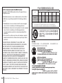
* This applies only to products distributed by Yamaha Corporation of America. (class A)
This device complies with Part 15 of the FCC Rules. Operation is
subject to the following two conditions:
(1) this device may not cause harmful interference, and (2) this
device must accept any interference received, including interference
that may cause undesired operation.
CAN ICES-3 (A)/NMB-3(A)
(can_a_02)
A 급 기기 ( 업무용 방송통신기자재 )
이 기기는 업무용 (A 급 ) 전자파적합기기로서 판매자 또는 사용자는
이 점을 주의하시기 바라며 , 가정외의 지역에서 사용하는 것을 목적
으로 합니다 .

3
VXL1B-16P/VXL1W-16P Owner’s Manual
PLEASE READ CAREFULLY BEFORE
PROCEEDING
Please keep this manual in a safe place for future
reference.
WARNING
Always follow the basic precautions listed
below to avoid the possibility of serious
injury or even death from electrical shock,
short-circuiting, damages, fire or other
hazards. These precautions include, but are
not limited to, the following:
If you notice any abnormality
• Ifanyofthefollowingproblemsoccur,
immediatelyturnoffthePoEinjectororthePoE
networkswitchanddisconnectthecable.
- TheLANcabledamaged.
- Unusual smells or smoke are emitted.
- Someobject,orwaterhasbeendroppedinto
the product.
- Thereisasuddenlossofsoundduringuseof
the product.
- Cracksorothervisibledamageappearonthe
product.
Then have the product inspected or repaired
byqualiedYamahaservicepersonnel.
Location and connection
• UseaCAT5eorhigherLANcabletoconnect
thisproductwithaPoEinjectororthePoE
networkswitch.Ifyouconnectacablethat
doesnotcomplywithspecications,or
connectaattypeorslimtypecable,reor
malfunctionsmightoccur.
• Donotusetheoptionalbracketsforother
speakersbesidestheonesspecied.Doingso
maycauseanaccident.
• DonotdamagetheLANcable.Failureto
observethisprecautioncouldresultinre,
electricshock,ordamagetotheproduct.
- Donotplaceheavyobjectsonthecable.
- Donotprocessthecableinanyway.
- Donotusestaplestoxthecableinplace.
- Donotapplyexcessiveforcetothecable.
- Besuretokeepthecableawayfromanything
hot.
Do not open
• Donotdisassembleormodifythisdevice
(paintingexcepted).
Water warning/Fire warning
• Donotexposetheproducttorain,useitnear
waterorindamporwetconditions,orplace
onitanycontainers(suchasvases,bottlesor
glasses)containingliquidswhichmightspill
intoanyopenings.
• Donotplaceanyburningitemsoropenames
neartheproduct,sincetheymaycauseare.
Hearing loss
• Beforeconnectingtheproducttootherdevices,
turnoffthepowerforalldevices.Also,before
turningthepowerofalldevicesonoroff,
make sure that all volume levels are set to the
minimum.Failingtodosomayresultinhearing
loss,electricshock,ordevicedamage.
CAUTION
Always follow the basic precautions listed
below to avoid the possibility of physical
injury to you or others, or damage to the
product or other property. These precautions
include, but are not limited to, the following:
Location and connection
• Donotplacetheproductinanunstable
positionwhereitmightaccidentallyfallover
andcauseinjuries.
• Donotplacetheproductinalocationwhereit
maycomeintocontactwithcorrosivegasesor
saltair.Doingsomayresultinmalfunction.
• Beforemovingtheproduct,removeallconnected
cables.
• Besuretocontactaprofessionalinstaller,ifthe
speakerinstallationrequiresconstructionwork,and
makesuretoobservethefollowingprecautions.
-
Choosemountinghardwareandaninstallation
locationthatcansupporttheweightoftheproduct.
- Avoidlocationsthatareexposedtoconstant
vibration.
- Usetherequiredtoolstoinstalltheproduct.
- Inspecttheproductperiodically.
• Whentransportingthisproduct,takecarenot
todropit.Droppingthisproductmaycauseit
tobedamaged,ormaycausepersonalinjury.
• Donotroutecableswheresomeonemight
tripoverthem,suchasinalocationwhere
peoplepass.Trippingonacablemaycausea
personorthisproducttofalldown,resultingin
personalinjuryordamagetotheproduct.
PA_en_9 1/2
PRECAUTIONS

4
VXL1B-16P/VXL1W-16P Owner’s Manual
PRECAUTIONS
Handling caution
• Donothangheavyobjectsfromthisdevice.
• Avoidapplyingexcessiveforcetotheswitches
orconnectorstopreventinjuries.
Yamahacannotbeheldresponsiblefordamage
causedbyimproperuseormodificationstothe
product,ordatathatislostordestroyed.
PA_en_9 2/2
NOTICE
Toavoidthepossibilityofmalfunction/damageto
theproduct,damagetodata,ordamagetoother
property,followthenoticesbelow.
Handling and maintenance
DonotusetheproductinthevicinityofaTV,
radio,AVequipment,mobilephone,orother
electricproducts.Otherwise,theproduct,TV,or
radiomaygeneratenoise.
Donotexposetheproducttoexcessivedust
orvibration,orextremecoldorheat(suchasin
directsunlight,nearaheater,orinacarduring
theday),inordertopreventthepossibility
ofpaneldisfiguration,unstableoperation,or
damagetotheinternalcomponents.
Condensation can occur in the product due to
rapid,drasticchangesinambienttemperature—
when the product is moved from one location to
another,orairconditioningisturnedonoroff,for
example.Usingtheproductwhilecondensationis
presentcancausedamage.Ifthereisreasonto
believethatcondensationmighthaveoccurred,
leave the product for several hours without
turningonthepoweruntilthecondensationhas
completelydriedout.
Whenplacingthespeakerfacedown,always
place it on a flat surface.
Donottouchthespeakerdriverunit.
Airblowingoutofthebassreflexportsisnormal,
andoftenoccurswhenthespeakerishandling
programmaterialwithheavybasscontent.
Donotplacevinyl,plasticorrubberobjectson
theproduct,sincethismightdiscolorthepanel.
Whencleaningtheproduct,useadryandsoft
cloth.Donotusepaintthinners,solvents,cleaning
fluids,orchemical-impregnatedwipingcloths.
DonotuseaLANcableofaformthatwouldplace
undue strain on the connector when connected to
this product.
Information
This is a class A product. Operation of this
product in a residential environment could cause
radio interference.
Topreventelectromagneticinterference,useSTP
(ShieldedTwistedPair)cable.
About this manual
The illustrations as shown in this manual are for
instructionalpurposesonly.
Apple,theApplelogo,andiPadareregistered
trademarksofAppleInc.intheUnitedStatesand
in other countries.
Thecompanynamesandproductnamesin
thismanualarethetrademarksorregistered
trademarks of their respective companies.
About disposal
Thisproductcontainsrecyclablecomponents.
Whendisposingofthisproduct,pleasecontact
the appropriate local authorities.
FordetailsontheopensourcelicenseofDante’s
Ultimo,refertothewebsiteoftheAudinate
Corporation.
https://www.audinate.com/software-licensing
Themodelnumber,serialnumber,power
requirements,etc.,maybefoundonornear
thenameplate,whichisattherearofthe
unit.Youshouldnotethisserialnumberinthe
spaceprovidedbelowandretainthismanual
asapermanentrecordofyourpurchasetoaid
identification in the event of theft.
Model No.
Serial No.
(rear_en_01)

5
VXL1B-16P/VXL1W-16P Owner’s Manual
PRECAUTIONS ........................................................................... 3
NOTICE .................................................................................. 4
Information .............................................................................4
Introduction ..................................................................................6
What you’ll need ....................................................................6
About the software .................................................................6
Using the PDF manuals .........................................................6
Included accessories ............................................................7
Optional accessories .............................................................7
Controls and Connectors .............................................................8
Front panel/Rear panel ..........................................................8
Setting method ......................................................................9
Installing the speakers ...............................................................11
Initialization ................................................................................14
Painting ...................................................................................... 15
Painting the grille .................................................................15
Painting the speaker enclosure ...........................................16
Contents
Attaching the horizontal coupling bracket (HCB‑L1B) ...............17
Attaching the wall mount bracket (WMB‑L1) .............................18
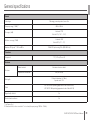
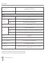
General specifications ...............................................................21
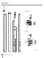
Dimensions ..............................................................................208
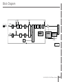
Block Diagram .........................................................................209

6
VXL1B-16P/VXL1W-16P Owner’s Manual
Thank you for purchasing the Yamaha VXL1B-16P or VXL1W-16P
speaker system.
This product is a speaker system used for amplifying sound in
conference rooms and similar spaces. It allows the speaker system to
be networked via a Dante network and PoE (Power over Ethernet). This
owner’s manual provides instructions for planning, installing, and setting
up the system. Be sure to read this owner’s manual before installation.
Also, keep this guide in a safe place for reference after you have finished
reading it.
What you’ll need
• PoE injector or PoE network switch that complies with
IEEE802.3at(PoE+) or IEEE802.3af
This is used between this unit and a Dante device such as the MRX7-D
in order to supply power to this unit.
PoE injectors or PoE network switches are collectively referred to as “PSE
(Power Sourcing Equipment).”
• Ethernet cable (CAT5e or higher)
This is used between the Dante device such as the MRX7-D and the
PSE, and between the PSE and this unit.
About the software
ProVisionaire Touch
ProVisionaire Touch is an application for remotely controlling this product
from a tablet (iPad) via a Wi-Fi network.
Dante Controller
Dante Controller is application software for setting up a Dante network
and specifying audio routing.
This product is supported by Dante Controller V3.2.x and later.
The computer on which Dante Controller is installed must be equipped
with an Ethernet port that supports gigabit Ethernet.
For information about this software, refer to the Yamaha Pro Audio
website.
https://www.yamaha.com/proaudio/
For details on how to download and install the software, and on detailed
settings, refer to the above website and to the installation guide that is
included with the downloaded program.
Using the PDF manuals
Each user guide is an electronic file in PDF format. These files can
be viewed on your computer. If you use “Adobe
®
Reader
®
” as the
viewing software on your computer, you’ll be able to quickly search
for terms, print specific sections that you need, or click links to open
the corresponding section. Searching for terms and following links are
particularly convenient functions that are possible only with an electronic
file. We encourage you to take advantage of such functions.
The latest version of Adobe Reader can be downloaded from the
following website.
http://www.adobe.com/
Introduction

7
VXL1B-16P/VXL1W-16P Owner’s Manual
Introduction
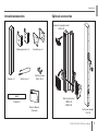
Included accessories Optional accessories
English
Deutsch
FrançaisEspañol
Português
Italiano
Русский
한국어
中文
日本語
JA
ES
ZH
KO
RU
IT
PT
FR
DE
EN
SPEAKER SYSTEM
VXL1B-16P
VXL1W-16P
Owner’s Manual
Bedienungsanleitung
Mode d’emploi
Manual de instrucciones
Manual do Proprietario
Manuale di istruzioni
Руководство по льзователя
使用说明书
取扱説明書
Speaker x 1
Mounting bracket x 2 Bracket base x 2
Owner’s Manual
(this book)
Safety wire x 1
Template x 1
Pole mount adapter
PA‑L1B
Wall mount bracket
WMB‑L1B
WMB‑L1W
Horizontal coupling bracket
HCB‑L1B
Machine screws
(M5 x 10) x 2

8
VXL1B-16P/VXL1W-16P Owner’s Manual
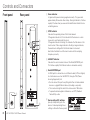
Controls and Connectors
Front panel Rear panel
1
4
5
3
2
1
Power indicator
Lit green when power is being supplied correctly. This goes dark
approximately 30 seconds after startup. During initialization, it flashes
rapidly. It flashes when you execute the identification function from a
controlling device.
2
SYNC indicator
Indicates the operating status of the Dante network.
If the green indicator is lit, this indicates that the device is a clock
slave and is synchronized to the clock.
If the green indicator is flashing, this indicates that the device is the
clock master. If the orange indicator is flashing at regular intervals,
the word clock setting within the Dante network is incorrect.
Use Dante Controller to set the clock master and the sampling
frequency correctly.
3
LINK/ACT indicator
Indicates the communication status of the Dante/NETWORK port.
This flashes rapidly if the Ethernet cable is connected correctly.
4
Dante/NETWORK port
An RJ45 port for connection via an Ethernet cable (CAT5e or higher)
to a Dante device such as the MRX7-D, through a PSE (Power
Sourcing Equipment) unit.
•Do not connect this port to anything other than a Dante-enabled
device or a gigabit Ethernet device (including a computer).
•The maximum length of cable that can be used is 100 meters.
•To prevent electromagnetic interference, use STP (Shielded
Twisted Pair) cable.
5
Device settings DIP switches
Specify startup settings for the
device. A label explaining these
settings is affixed to the rear panel.

9
VXL1B-16P/VXL1W-16P Owner’s Manual
Controls and Connectors
Setting method
Turn off the power of the PSE (Power Sourcing Equipment) before you
change these settings. Even if you change these settings while the
power is on, the change is not applied until the power is turned off.
For details, refer to the following.
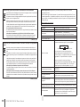
DIP switch
Position
The DIP switch is in the upward position
DIP switch
Position
The DIP switch is in the downward position
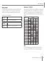
DIP switches 1–4 (UNIT ID)
These specify the UNIT ID of the device. The UNIT ID is assigned as the
value specified by DIP switches 1–4 plus 100, producing a value in the
range of 101–115 (Hexadecimal 65–73). In the table below, “up” and
“down” indicate whether the DIP switch is in the upward or downward
position.
UNIT ID
DIP switch
1 2 3 4
101 down up up up
102 up down up up
103 down down up up
104 up up down up
105 down up down up
106 up down down up
107 down down down up
108 up up up down
109 down up up down
110 up down up down
111 down down up down
112 up up down down
113 down up down down
114 up down down down
115 down down down down
RESERVED up up up up
NOTE
If you are connecting multiple VXL1B-16P or VXL1W-16P units in the
same network, set the UNIT ID so that the settings do not overlap.

10
VXL1B-16P/VXL1W-16P Owner’s Manual
Controls and Connectors
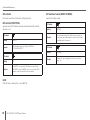
DIP switch 5
Not used. Leave this at the factory setting (upward).
DIP switch 6 (IP SETTING)
Specifies how the IP address used for communication with external
devices is set.
DIP switch
Setting
UNIT ID
Content
The IP address is specified by the UNIT ID as
“192.168.0.(UNIT ID).”
DIP switch
Setting
PC
Content
If a DHCP server exists, the IP address is specified by
the DHCP server. If a DHCP server does not exist, the IP
address is specified by the link local address.
NOTE
With the factory settings this is set to UNIT ID.
DIP switches 7 and 8 (START UP MODE)
Specify the startup mode.
DIP switch
Setting
RESUME
Content
The normal operating mode. When the power turns on,
the unit starts up and maintains the state in which it was
immediately prior to power-off.
DIP switch
Setting
INITIALIZE
Content
Initializes the unit, returning it to the factory-set state
(page 14).

11
VXL1B-16P/VXL1W-16P Owner’s Manual
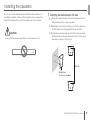
Installing the speakers
You can use the included mounting bracket to install the speaker on a
wall. Before installation, make sure the installation area can support the
weight of the speaker. Do not install on wallboard or similar materials.
CAUTION
Do not install the speakers horizontally, as the speakers may fall.
1
Attaching the bracket base to the wall
1-1
Place the included template on the wall, to decide where the
holes should go for the screws and cables.
1-2
Make holes in the wall for the cables, and pull the cables from
the PSE (Power Sourcing Equipment) through the holes.
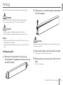
1-3
Install the bracket base onto the wall. Position the narrow part
of the bracket base downward (towards the floor). The bracket
base holes should be 5.3 mm in size.
Bracket base
(screws not included)
444 mm

12
VXL1B-16P/VXL1W-16P Owner’s Manual
Installing the speakers
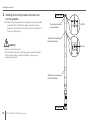
2
Installing the mounting bracket and safety wire
onto the speakers
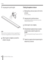
2-1
Install the mounting bracket onto the speaker using the included
screws (M5×10). Install both the upper and lower mounting
brackets at the position of the third hole. Install the safety wire at
the topmost hole position.
CAUTION
•Use the included safety wire.
•If the included safety wire is not long enough, consider the weight
of the speaker and the installation conditions, and procure an
appropriate safety wire.
Screw hole for safety
wire installation
Upper side
Lower side
Screw hole for mounting
bracket installation
Screw hole for mounting
bracket installation
2.0 N·m
2.0 N·m

13
VXL1B-16P/VXL1W-16P Owner’s Manual
Installing the speakers
3
Set the device setting DIP switches
3-1
On the rear panel, set the device setting DIP switches
(page 9) as appropriate for your installation.
NOTE
If you are connecting multiple VXL1B-16P or VXL1W-16P units
in the same network, set the UNIT ID so that the settings do not
overlap.
4
Connect to the Dante/NETWORK port
4-1
Connect an Ethernet cable (CAT5e or higher) from the PSE
(Power Sourcing Equipment) to the Dante/NETWORK port.
NOTE
Connect the Ethernet cable to the LAN port of the PSE (Power Sourcing
Equipment).
5
Attach the safety wire to the wall
CAUTION
Attach the safety wire above the speaker, and do not allow it to be slack.
6
Installing the main speaker unit onto the wall
6-1
Fit the bracket base together with the mounting bracket by
inserting from the top, making sure to insert the mounting
bracket all the way until the parts lock together.
NOTICE
•When installing the speaker, grasp it in the middle by its sides.
•Make sure that the mounting base and mounting bracket are locked
together in two places, top and bottom.
When removing, pick up the entire speaker while lightly pushing to the
left.
7
Make patch settings from Dante Controller
For details, refer to the Dante Controller user guide.
8
Power‑on the PSE

14
VXL1B-16P/VXL1W-16P Owner’s Manual
If you want to return (initialize) the internal memory to its factory-set
state, such as after changing the location of installation, proceed as
follows.
1
Turn off the PSE (Power Sourcing Equipment).
2
On the rear panel, set device setting DIP switch 7
downward and switch 8 upward (INITIALIZE).
3
Power‑on the PSE.
Initialization begins.
•During initialization:
The POWER indicator flashes rapidly.
•When initialization is complete:
The POWER indicator flashes slowly.
•If initialization fails:
The POWER indicator is unlit.
NOTICE
Do not power-off the PSE while initialization is in progress. This could
cause malfunctions.
4
Verify that initialization is complete, and power‑off
the PSE.
5
Set device setting DIP switches 7 and 8 both in
the upward (RESUME) position.
6
Power‑on the PSE.
The unit starts in the factory-set state.
Initialization

15
VXL1B-16P/VXL1W-16P Owner’s Manual
Painting
We recommend that you paint this product using acrylic lacquer.
WARNING
Do not disassemble or modify this product (painting excepted).
This could cause electrocution, fire, injury, or malfunctions.
CAUTION
•Provide adequate ventilation while performing this work.
•When removing or attaching the grille, take care to avoid injury.
NOTICE
•When using volatile solvents, be careful of fire. Failure to take care
might cause fire or accidents.
•Damage caused by painting the speaker is not covered by the war-
ranty.
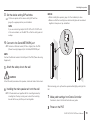
Painting the grille
1
Remove four screws each from the top and
bottom panels of the speaker, and remove the top
and bottom panels.
2
Taking care not to scratch the grille, slowly detach
it from the speaker.
CAUTION
When detaching the grille, wear gloves to avoid injuring your hand on
the edge of the grille.
3
Remove the emblem from the surface of the grille.
The emblem is fastened with adhesive tape.
4
Before painting, remove any dust or dirt from the
grille.
Do not use sandpaper.

16
VXL1B-16P/VXL1W-16P Owner’s Manual
Painting
5
Use spray paint to paint the grille.
NOTE
Make sure the holes in the grille do not become clogged with paint. If
the holes become clogged with paint, sound quality may be affected.
6
When the paint is completely dry, attach the
emblem to the grille.
Painting the speaker enclosure
1
Before painting, remove any dust or dirt from the
enclosure.
Do not use sandpaper.
2
Use spray paint to paint the enclosure.
Cover the speaker unit, baffle, and connectors using masking
materials to avoid paint contact.
3
Allow the paint to dry completely.
4
After painting the speaker enclosure, top plate,
and bottom plate, reattach the grille to the
speaker.
To do so, align the grille with the edge of the speaker and fit it into
place.
5
Fasten the top panel and bottom panel using the
screws that you removed.

17
VXL1B-16P/VXL1W-16P Owner’s Manual
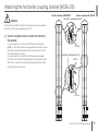
Attaching the horizontal coupling bracket (HCB-L1B)
CAUTION
Do not attach the HCB-L1B horizontal coupling bracket to any product
other than a VXL1 series speaker system unit.
1
Use the included screws to attach the bracket to
the speaker.
If you are using this in conjunction with the wall mount bracket
(WMB-L1), attach the horizontal coupling bracket (S) to the first hole
from the top, and attach the horizontal coupling bracket (L) to the
7th and 8th holes from the top.
If you are using this in conjunction with the pole mount adapter
(PA-L1B), attach the horizontal coupling bracket (S) to the first hole
from the top, and attach the horizontal coupling bracket (L) to the
4th and 5th holes from the top.
Horizontal coupling bracket (S)
Horizontal coupling bracket (L)
2.0 N·m
2.0 N·m
2.0 N·m
Used in common with WMB-L1 Used in common with PA-L1B

18
VXL1B-16P/VXL1W-16P Owner’s Manual
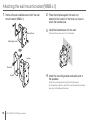
1
Remove the pre‑installed screws from the wall
mount bracket (WMB‑L1).
Bracket base
Loosen
Loosen
Remove
Mounting bracket
2
Place the template against the wall, and
determine the location of the holes you’ll use to
attach the bracket base.
3
Install the bracket base onto the wall.
The bracket base holes are 12 mm in diameter.
4
Attach the mounting bracket and safety wire to
the speakers.
Attach the mounting bracket using the included screws.
For the position at which to attach the mounting bracket and safety
wire, refer to the following illustration.
Attaching the wall mount bracket (WMB-L1)

19
VXL1B-16P/VXL1W-16P Owner’s Manual
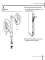
Attaching the wall mount bracket (WMB‑L1)
CAUTION
Attach the safety wire above the speaker, and do not allow it to be slack.
2.0 N·m
2.0 N·m
5
Connect an Ethernet cable (CAT5e or higher)
from the PSE (Power Sourcing Equipment) to the
Dante/NETWORK port.
6
Insert the mounting bracket from above into the
bracket base so that they fit together.

20
VXL1B-16P/VXL1W-16P Owner’s Manual
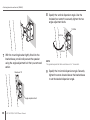
Attaching the wall mount bracket (WMB‑L1)
7
With the mounting bracket tightly fitted into the
bracket base, provisionally secure the speaker
using the angle adjustment bolt that you removed
earlier.
Maximum 10°
Angle adjustment bolt
8
Specify the vertical dispersion angle. Use the
included hex wrench to securely tighten the two
angle adjustment bolts.
12.0 N·m
2.0 N·m
6.0 N·m
NOTE
The guide stamped into the bracket base is in 2° increments.
9
Specify the horizontal dispersion angle. Securely
tighten the screw located above the bracket base
to set the desired dispersion angle.
Sidan laddas...
Sidan laddas...
Sidan laddas...
Sidan laddas...
Sidan laddas...
Sidan laddas...
Sidan laddas...
Sidan laddas...
Sidan laddas...
Sidan laddas...
Sidan laddas...
Sidan laddas...
-
 1
1
-
 2
2
-
 3
3
-
 4
4
-
 5
5
-
 6
6
-
 7
7
-
 8
8
-
 9
9
-
 10
10
-
 11
11
-
 12
12
-
 13
13
-
 14
14
-
 15
15
-
 16
16
-
 17
17
-
 18
18
-
 19
19
-
 20
20
-
 21
21
-
 22
22
-
 23
23
-
 24
24
-
 25
25
-
 26
26
-
 27
27
-
 28
28
-
 29
29
-
 30
30
-
 31
31
-
 32
32


Yamaha VXL1W Bruksanvisning
- Typ
- Bruksanvisning
- Denna manual är också lämplig för
på andra språk
- italiano: Yamaha VXL1W Manuale del proprietario
- čeština: Yamaha VXL1W Návod k obsluze
- español: Yamaha VXL1W El manual del propietario
- Deutsch: Yamaha VXL1W Bedienungsanleitung
- polski: Yamaha VXL1W Instrukcja obsługi
- português: Yamaha VXL1W Manual do proprietário
- français: Yamaha VXL1W Le manuel du propriétaire
- 日本語: Yamaha VXL1W 取扱説明書
- Türkçe: Yamaha VXL1W El kitabı
- English: Yamaha VXL1W Owner's manual
- dansk: Yamaha VXL1W Brugervejledning
- русский: Yamaha VXL1W Инструкция по применению
- suomi: Yamaha VXL1W Omistajan opas
- Nederlands: Yamaha VXL1W de handleiding
- română: Yamaha VXL1W Manualul proprietarului