
1
Maxi Heat Digital
Byte av elpatron/tätning
MA45-24S
SVENSKA
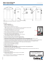
NOTE!
This unit has been upgraded with
titanium heating element(s)
Installed by Date
Detta behövs: Skruvmejsel, Hylsnyckel, 1 st buntband
Gör så här:
1. Stäng av elvärmaren.
2. Slå av huvudströmbrytaren.
3. Stäng av cirkulationspumpen.
4. Stäng ventilen före elvärmaren (på röret IN).
OBS! Kontrollera att röret UT har en backventil som hindrar vattnet från att rinna bakåt.
5. Lossa dräneringspluggen och töm elvärmarens tunna på vatten.
6. Sätt tillbaka dräneringspluggen när tunnan är tom.
7. Lossa lockets två skruvar (A) och fäll upp locket.
8. Slå av samtliga automatsäkringar inne i elvärmaren (se bild B).
9. Lossa serviceluckans fyra skruvar på gaveln och öppna den.
10. Dra ur temp.sensorn för överhettningsskyddet.
Temp.sensornäralltidplaceradickanpåelpatronnr2(sesid2).
11. Lossa kablaget från elpatronen (matning och jord).
12. Skruva loss elpatronen (eller eventuell täckbricka) från tunnan.
13.Ersättdenbentligapackningenmeddennyaröda packningen.
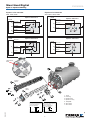
14. Nya patroner levereras för 380-415V. OBS! Vid 220-240V ska de tre kopplingsblecken demonteras, se sid 2.
Kontrollera att den nya patronen är korrekt kopplad för den aktuella driftspänningen.
15. Dra fast de nya patronerna (och täckbrickorna) med max 3Nm i tunnan. OBS! Använd rätt skruvlängd till respektive detalj:
Titanpatroner kräver skruvlängd 30 mm, Incoloypatroner och täckbrickor kräver skruvlängd 16-20 mm.
16.Stoppatillbakatemp.sensornickanpåpatronnr2ochsäkradenmedettbuntband.
17. Kontrollera att dräneringspluggen är åtdragen.
18. Öppna ventilen på röret IN (före elvärmaren).
19. Sätt på cirkulationspumpen.
20. Vänta tills elvärmaren är fylld med vatten.
Elvärmaren får under inga omständigheter startas utan att den är helt fylld med vatten.
21. Kontrollera att det inte läcker vatten vid patronerna.
22. Montera tillbaka kablaget på patronerna. Se medföljande kopplingsschema (sid 2) för 220-240V eller 380-415V.
23. Slå på samtliga automatsäkringar.
24. Stäng alla luckor.
25. Slå på huvudströmbrytaren.
26. Starta elvärmen. Elvärmaren kommer ihåg den senast inställda
önskade pooltemperaturen.
Om Incoloypatroner ersätts av titanpatroner ska medföljande dekal
fästas vid typskylten på elvärmarens baksida. C. Medföljande dekal
B. Automatsäkring
På
Av
Servicelucka
UT
Typskylt
IN
Dräneringsplugg
A

2
Maxi Heat Digital
Byte av elpatron/tätning
MA45-24S
SVENSKA
3-fas 220-240V
9, 12, 15kW
Elpatron utförande B
Elpatron utförande A
Maxi Heat Digital
E10039-1
101123 T.S
L1
L1
K1-4B
K1-4B
L2
L2
L3
L3
Rosa
Rosa
Vit
Vit
Svart 6mm²
Svart 6mm²
Brun 6mm²
Brun 6mm²
Vit 6mm²
Vit 6mm²
Vit 6mm²
Vit 6mm²
Brun 6mm²
Brun 6mm²
Svart 6mm²
Svart 6mm²
Vit
Blå
Blå
Blå
Rosa
3-fas 380-415V
9 , 12, 15, 18kW
Elpatron utförande B
Elpatron utförande A
Maxi Heat Digital
E10040-1
101123 T.S
L1
L1
K1-4B
K1-4B
L2
L2
L3
L3
Rosa
Rosa
Vit
Vit
Vit 6mm²
Vit 6mm²
Brun 6mm²
Brun 6mm²
Svart 6mm²
Svart 6mm²
Vit
Blå
Blå
Blå
Rosa
3-fas 380-415V
9 , 12, 15, 18kW
Elpatron utförande B
Elpatron utförande A
Maxi Heat Digital
E10040-1
101123 T.S
L1
L1
K1-4B
K1-4B
L2
L2
L3
L3
Rosa
Rosa
Vit
Vit
Vit 6mm²
Vit 6mm²
Brun 6mm²
Brun 6mm²
Svart 6mm²
Svart 6mm²
Vit
Blå
Blå
Blå
Rosa
5
7
2
1
4
3
7
6
30
20
Temp.sensor
HÄR
Pos 7:
For incoloy elements
(pos 4)
and cover
(pos 5)
.
Screw TPS RX 6x20
Part No.19910397
Incoloy-
patron
Titan-
patron
1. Tunna
2. Packning
3. Elpatron titan
4. Elpatron Incoloy
5. Täckplatta
6. Skruv 6x30
7. Skruv 6x20
Pos 6:
For titanium elements
(pos 3)
Screw TPS RX 6x30
Part No.19910398
Elpatron 3-fas 220-240V Elpatron 3-fas 380-415V
9kW, 12kW, 15kW 9kW, 12kW, 15kW, 18kW

3
Maxi Heat Digital
Change of heating element/gasket
MA45-24E
ENGLISH
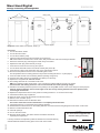
NOTE!
This unit has been upgraded with
titanium heating element(s)
Installed by Date
C. Enclosed label
B. Automatic fuse
On
Off
Service window
OUT
Rating plate
IN
Drain plug
A
Required: Screw driver, box spanner, strap 1 pc
Procedure:
1. Turn off the electric heater.
2. Turn off the main switch.
3. Turn off the circulation pump.
4. Close the valve ahead of the electric heater (on the hose IN).
NB!CheckthatthehoseOUThasacheck-valve,thatpreventsthewaterfromowingbackwards.
5. Disconnect the drain plug and empty the heater body of the water.
6. Replace the drain plug when the body is empty.
7. Undo the two screws on the cover (A) and open it.
8. Turn off all the automatic fuses in the electric heater (see picture B).
9. Undo the four screws of the inspection door on the end wall and open it.
10. Pull out the temperature sensor for the overheating limit control.
The temperature sensor is always placed in the pocket of heating element no. 2 (see page 2).
11. Undo the cable harness from the heating element (feeding and ground).
12. Unscrew the heating element (or possible cover plate) from the body.
13. Replace the old gasket with the new red one.
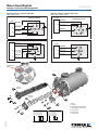
14. The heating elements are connected for 380-415V.
NB! If the operating voltage is 220-240V, 3 pcs connection tin plates shall be removed, see page 2.
Check that the new heating element is correct connected for the actual operating voltage.
15. Install the new heating elements (and the cover plates) in the body. NB! Use the correct screw length for each purpose:
Titanium heating elements need a screw length of 30 mm, Incoloy heating elements and cover plates need a
screw lenght of 16-20 mm.
16. Replace the temperature sensor in the pocket on heating element no. 2. Secure it with a strap.
17. Check that the drain plug is tightened
18. Open the valve on the hose IN (ahead of the electric heater).
19. Switch on the circulation pump.
20.Waituntiltheelectricheaterislledwithwater.
Theelectricheatermustnotbestarteduntilitiscompletelylledwithwater.
21. Check that there are no water leaks at the heating elements.
22. Reassemble the cable harness on the heating elements. See the enclosed wiring diagram for 220-240V or 380-415V.
23. Switch on all the automatic fuses.
24. Close all openings.
25. Turn on the main switch.
26. Start the electric heater. The electric heater remembers the last set
required pool temperature.
If Incoloy elements are replaced by titanium elements the enclosed label (C )
shall be attached beside the rating place on the back of the heater.

4
Maxi Heat Digital
Change of heating element/gasket
MA45-24E
ENGLISH
3-phase220-240V
9,12,15kW
HeatingelementB
Heatingelement A
MaxiHeatDigital
E10039-0
100114 T.S
L1
L1
K1-4B
K1-4B
L2
L2
L3
L3
Pink
Pink
White
White
Black4mm²
Black4mm²
Brown4mm²
Brown4mm²
White4mm²
White4mm²
White4mm²
White4mm²
Brown4mm²
Brown4mm²
Black4mm²
Black4mm²
White
Blue
Blue
Blue
Pink
3-phase380-415V
9,12,15,18kW
HeatingelementB
Heatingelement A
MaxiHeatDigital
E10040-0
100114 T.S
L1
L1
K1-4B
K1-4B
L2
L2
L3
L3
Pink
Pink
White
White
White4mm²
White4mm²
Brown4mm²
Brown4mm²
Black4mm²
Black4mm²
White
Blue
Blue
Blue
Pink
3-phase380-415V
9,12,15,18kW
HeatingelementB
Heatingelement A
MaxiHeatDigital
E10040-0
100114 T.S
L1
L1
K1-4B
K1-4B
L2
L2
L3
L3
Pink
Pink
White
White
White4mm²
White4mm²
Brown4mm²
Brown4mm²
Black4mm²
Black4mm²
White
Blue
Blue
Blue
Pink
5
7
2
1
4
3
7
6
30
20
Heating element 3-phase 220-240V Heating element 3-phase 380-415V
9kW, 12kW, 15kW 9kW, 12kW, 15kW, 18kW
Temp.sensor
HERE
Pos 7:
For incoloy elements
(pos 4)
and cover
(pos 5)
.
Screw TPS RX 6x20
Part No.19910397
Incoloy
element
Titanium
element
1. Body
2. Gasket
3. Heating element titanium
4. Heating element Incoloy
5. Cover plate
6. Screw 6x30
7. Screw 6x20
Pos 6:
For titanium elements
(pos 3)
Screw TPS RX 6x30
Part No.19910398
Black 6mm2
Black 6mm2
Brown 6mm2
Brown 6mm2
White 6mm2
White 6mm2
Black 6mm2
Black 6mm2
Brown 6mm2
Brown 6mm2
White 6mm2
White 6mm2
Black 6mm2
Brown 6mm2
White 6mm2
Black 6mm2
Brown 6mm2
White 6mm2
-
 1
1
-
 2
2
-
 3
3
-
 4
4


