
INSTRUCTION AND
SERVICE MANUAL
ORIGINAL INSTRUCTION
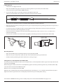
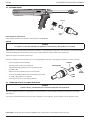
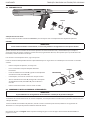
07536 Repetition Tool for Speed Rivets
Hydro-Pneumatic Power Tool
0753
TYPE
EN
Hydro-Pneumatic Power Tool
FR
Outil électrique hydropneumatique
DE
Hydropneumatisches Setzgerät
IT
Elettroutensile oleopneumatico
PL
Narzędzie pneumatyczno-hydrauliczne
ES
Herramienta hidroneumática
NL
Hydropneumatisch gereedschap
DA
Hydro-pneumatisk el-værktøj
FI
Hydropneumaattinen sähkötyökalu
NO
Hydropneumatisk verktøy
SV
Hydro-pneumatiskt elverktyg
PT
Ferramenta eléctrica hidropneumática


©2021 Stanley Black & Decker inc.
All rights reserved.
The information provided may not be reproduced and/or made public in any way and through any means (electronically or
mechanically) without prior explicit and written permission from STANLEY Engineered Fastening. The information provided
is based on the data known at the moment of the introduction of this product. STANLEY Engineered Fastening pursues a
policy of continuous product improvement and therefore the products may be subject to change. The information provided
is applicable to the product as delivered by STANLEY Engineered Fastening. Therefore, STANLEY Engineered Fastening
cannot be held liable for any damage resulting from deviations from the original specications of the product.
The information available has been composed with the utmost care. However, STANLEY Engineered Fastening will not
accept any liability with respect to any faults in the information nor for the consequences thereof. STANLEY Engineered
Fastening will not accept any liability for damage resulting from activities carried out by third parties. The working names,
trade names, registered trademarks, etc. used by STANLEY Engineered Fastening should not be considered as being free,
pursuant to the legislation with respect to the protection of trade marks.
1. SAFETY DEFINITIONS ................................................................................................................................................... 4
1.1 GENERAL SAFETY RULES .......................................................................................................................................................................... 4
1.2 PROJECTILE HAZARDS .............................................................................................................................................................................. 4
1.3 OPERATING HAZARDS ............................................................................................................................................................................... 5
1.4 REPETITIVE MOTIONS HAZARDS............................................................................................................................................................ 5
1.5 ACCESSORY HAZARDS .............................................................................................................................................................................. 5
1.6 WORKPLACE HAZARDS ............................................................................................................................................................................. 5
1.7 NOISE HAZARDS .......................................................................................................................................................................................... 5
1.8 VIBRATION HAZARDS................................................................................................................................................................................. 5
1.9 ADDITIONAL SAFETY INSTRUCTIONS FOR PNEUMATIC & HYDRAULIC POWER TOOLS .................................................... 6
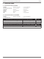
2. SPECIFICATIONS ............................................................................................................................................................ 7
2.1 SPECIFICATION FOR 07536 TOOL .......................................................................................................................................................... 7
2.2 SPECIFICATION FOR 07531 INTENSIFIER ............................................................................................................................................. 7
3. INTENT OF USE .............................................................................................................................................................. 8
3.1 TOOL DIMENSIONS - 07536 MODEL ..................................................................................................................................................... 8
4. PUTTING INTO SERVICE ................................................................................................................................................9
4.1 AIR SUPPLY .................................................................................................................................................................................................... 9
4.2 AIR CURSORS ..............................................................................................................................................................................................10
4.3 LOADING AND RELOADING THE TOOL ..............................................................................................................................................10
4.4 OPERATING PROCEDURE ........................................................................................................................................................................12
5. SERVICING THE TOOL..................................................................................................................................................13
5.1 PNEUMATIC CONTROL BOX ...................................................................................................................................................................13
5.2 DAILY .............................................................................................................................................................................................................13
5.3 WEEKLY .........................................................................................................................................................................................................13
5.4 MOLY LITHIUM GREASE EP 3753 SAFETY DATA..............................................................................................................................13
5.5 SERVICE KIT ..................................................................................................................................................................................................14
5.6 AIR CURSOR TOOL, INTENSIFIER & CONTROL BOX ASSEMBLY 07536-02100 ......................................................................15
6. MAINTENANCE ............................................................................................................................................................16
6.1 DISMANTLING 07536-02200 .................................................................................................................................................................16
6.2 GENERAL ASSEMBLY OF BASE TOOL 07536-02200 .......................................................................................................................18
6.3 PARTS LIST FOR BASE TOOL 07536-02200 .......................................................................................................................................19
6.4 DISMANTLING INSTRUCTIONS ............................................................................................................................................................. 20
6.5 PROTECTING THE ENVIRONMENT .......................................................................................................................................................21
6.6 INTENSIFIER 07531-02200 ......................................................................................................................................................................21
7. PRIMING ......................................................................................................................................................................23
7.1 OIL DETAILS ................................................................................................................................................................................................. 23
7.2 HYSPIN® VG32 AND AWS 32 OIL SAFETY DATA ..............................................................................................................................23
7.3 PRIMING PROCEDURE..............................................................................................................................................................................23
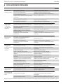
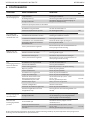
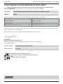
8. FAULT DIAGNOSIS ....................................................................................................................................................... 24
9. EC DECLARATION OF CONFORMITY .......................................................................................................................... 26
10. UK DECLARATION OF CONFORMITY .........................................................................................................................27
11. PROTECT YOUR INVESTMENT! ...................................................................................................................................28
3
ORIGINAL INSTRUCTION ENGLISH

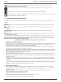
This instruction manual must be read by any person installing or operating this tool with particular attention to the
following safety rules.
Always wear impact-resistant eye protection during operation of the tool. The grade of protection required should
be assessed for each use.
Use hearing protection in accordance with employer’sinstructions and as required by occupational health and
safety regulations.
Use of the tool can expose the operator’shands to hazards, including crushing, impacts, cuts and abrasions and
heat. Wear suitable gloves to protect hands.
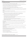
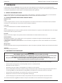
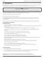
1. SAFETY DEFINITIONS
The denitions below describe the level of severity for each signal word. Please read the manual and pay attention to these
symbols.
DANGER: Indicates an imminently hazardous situation which, if not avoided, will result in death or serious injury.
WARNING: Indicates apotentially hazardous situation which, if not avoided, could result in death or serious injury.
CAUTION: Indicates apotentially hazardous situation which, if not avoided, may result in minor or moderate injury.
CAUTION: Used without the safety alert symbol indicates apotentially hazardous situation which, if not avoided, may
result in property damage.
Improper operation or maintenance of this product could result in serious injury and property damage. Read and
understand all warnings and operating instructions before using this equipment. When using power tools, basic safety
precautions must always be followed to reduce the risk of personal injury.
SAVE ALL WARNINGS AND INSTRUCTIONS FOR FUTURE REFERENCE
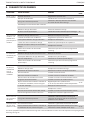
1.1 GENERAL SAFETY RULES
• For multiple hazards, read and understand the safety instructions before installing, operating, repairing, maintaining,
changing accessories on, or working near the tool. Failure to do so can result in serious bodily injury.
• Only qualied and trained operators must install, adjust or use the tool.
• DO NOT use outside the design intent of placing STANLEY Engineered Fastening Blind Rivets.
• Use only parts, fasteners, and accessories recommended by the manufacturer.
• DO NOT modify the tool. Modications can reduce the eectiveness of safety measures and increase the risks to the
operator. Any modication to the tool undertaken by the customer will be the customer’sentire responsibility and void
any applicable warranties.
• Do not discard the safety instructions; give them to the operator.
• Do not use the tool if it has been damaged.
• Prior to use, check for misalignment or binding of moving parts, breakage of parts, and any other condition that aects
the tool’soperation. If damaged, have the tool serviced before using. Remove any adjusting key or wrench before use.
• Tools shall be inspected periodically to verify that the ratings and markings required by this part of ISO 11148 are
legibly marked on the tool. The employer/user shall contact the manufacturer to obtain replacement marking labels
when necessary.
• The tool must be maintained in asafe working condition at all times and examined at regular intervals for damage
and function by trained personnel. Any dismantling procedure will be undertaken only by trained personnel. Do not
dismantle this tool without prior reference to the maintenance instructions.
1.2 PROJECTILE HAZARDS
• Disconnect the tool from the air supply before performing any maintenance, attempting to adjust, t or remove anose
assembly or accessories.
• Be aware that failure of the workpiece or accessories, or even of the inserted tool itself can generate high-velocity
projectiles.
• Always wear impact-resistant eye protection during operation of the tool. The grade of protection required should be
assessed for each use.
• The risks to others should also be assessed at this time.
• Ensure that the workpiece is securely xed.
• Check that the means of protection from ejection of fastener and/or mandrel is in place and is operative.
• Warn against the possible forcible ejection of mandrels from the front of the tool.
• DO NOT operate atool that is directed towards any person(s).
4
ENGLISH ORIGINAL INSTRUCTION

1.3 OPERATING HAZARDS
• Use of the tool can expose the operator’shands to hazards, including crushing, impacts, cuts and abrasions and heat.
Wear suitable gloves to protect hands.
• Operators and maintenance personnel shall be physically able to handle the bulk, weight and power of the tool.
• Hold the tool correctly; be ready to counteract normal or sudden movements and have both hands available.
• Keep tool handles dry, clean, and free from oil and grease.
• Maintain abalanced body position and secure footing when operating the tool.
• Release the start-and-stop device in the case of an interruption of the hydraulic supply.
• Use only lubricants recommended by the manufacturer.
• Contact with hydraulic uid should be avoided. To minimise the possibility of rashes, care should be taken to wash
thoroughly if contact occurs.
• Material Safety Data Sheets for all hydraulic oils and lubricants is available on request from your tool supplier.
• Avoid unsuitable postures as it is likely for these positions not to allow counteracting of normal or unexpected
movement of the tool.
• If the tool is xed to asuspension device, make sure that the xation is secure.
• Beware of the risk of crushing or pinching if nose equipment is not tted.
• DO NOT operate tool with the nose casing removed.
• Adequate clearance is required for the tool operator’shands before proceeding.
• When carrying the tool from place to place keep hands away from the trigger to avoid inadvertent activation.
• DO NOT abuse the tool by dropping or using it as ahammer.
• Care should be taken to ensure that spent mandrels do not create ahazard.
1.4 REPETITIVE MOTIONS HAZARDS
• When using the tool, the operator can experience discomfort in the hands, arms, shoulders, neck or other parts of the
body.
• While using the tool, the operator should adopt acomfortable posture whilst maintaining asecure footing and
avoiding awkward or o-balance postures. The operator should change posture during extended tasks; this can help
avoid discomfort and fatigue.
• If the operator experiences symptoms such as persistent or recurring discomfort, pain, throbbing, aching, tingling,
numbness, burning sensations or stiness, these warning signs should not be ignored. The operator should tell the
employer and consult aqualied health professional.
1.5 ACCESSORY HAZARDS
• Disconnect the tool from the air supply before tting or removing the nose assembly or accessory.
• Use only sizes and types of accessories and consumables that are recommended by the manufacturer of the tool; do
not use other types or sizes of accessories or consumables.
1.6 WORKPLACE HAZARDS
• Slips, trips and falls are major causes of workplace injury. Be aware of slippery surfaces caused by use of the tool and
also of trip hazards caused by the air line or hydraulic hose.
• Proceed with care in unfamiliar surroundings. There can be hidden hazards, such as electricity or other utility lines.
• The tool is not intended for use in potentially explosive atmospheres and is not insulated against contact with electric
power.
• Ensure that there are no electrical cables, gas pipes, etc., which can cause ahazard if damaged by use of the tool.
• Dress properly. Do not wear loose clothing or jewellery. Keep your hair, clothing and gloves away from moving parts.
Loose clothes, jewellery or long hair can be caught in moving parts.
• Care should be taken to ensure that spent mandrels do not create ahazard.
1.7 NOISE HAZARDS
• Exposure to high noise levels can cause permanent, disabling hearing loss and other problems, such as tinnitus (ringing,
buzzing, whistling or humming in the ears). Therefore, risk assessment and the implementation of appropriate controls
for these hazards are essential.
• Appropriate controls to reduce the risk may include actions such as damping materials to prevent workpieces from
“ringing”.
• Use hearing protection in accordance with employer’sinstructions and as required by occupational health and safety
regulations.
• Operate and maintain the tool as recommended in the instruction manual, to prevent an unnecessary increase in the
noise level.
1.8 VIBRATION HAZARDS
• Exposure to vibration can cause disabling damage to the nerves and blood supply of the hands and arms.
• Wear warm clothing when working in cold conditions and keep your hands warm and dry.
5
ORIGINAL INSTRUCTION ENGLISH

• If you experience numbness, tingling, pain or whitening of the skin in your ngers or hands, stop using the tool, tell
your employer and consult aphysician.
• Where possible Support the weight of the tool in astand, tensioner or balancer, because alighter grip can then be used
to support the tool.
1.9 ADDITIONAL SAFETY INSTRUCTIONS FOR PNEUMATIC & HYDRAULIC POWER TOOLS
• The operating supply air must not exceed 7 bar (100 PSI).
• Air under pressure can cause severe injury.
• Never leave operating tool unattended. Disconnect air hose when tool is not in use, before changing accessories or
when making repairs.
• DO NOT let air exhaust opening on the mandrel collector face in the direction of the operator or other persons. Never
direct air at yourself or anyone else.
• Whipping hoses can cause severe injury. Always check for damaged or loose hoses and ttings.
• Prior to use, inspect airlines for damage, all connections must be secure. Do not drop heavy objects on hoses. A sharp
impact may cause internal damage and lead to premature hose failure.]
• Cold air shall be directed away from hands.
• Whenever universal twist couplings (claw couplings) are used, lock pins shall be installed and whipcheck safety cables
shall be used to safeguard against possible hose-to-tool or hose-to-hose connection failure.
• DO NOT lift the placing tool by the hose. Always use the placing tool handle.
• Vent holes must not become blocked or covered.
• Keep dirt and foreign matter out of the hydraulic system of the tool as this will cause the tool to malfunction.
• Oil under pressure can cause severe injury.
• Prior to use, inspect hydraulic hoses for damage. All hydraulic connections must be clean, fully engaged and tight
before operation. Do not drop heavy objects on hoses. A sharp impact may cause internal damage and lead to
premature hose failure.
• DO NOT pull or move the intensier unit using the hoses. Always use the unit handle.
• Use only clean oil and lling equipment.
• Only recommended hydraulic uids may be used.
• Maximum temperature of the hydraulic uid at the inlet is 100°C (212°F).
WARNING: While a small amount of wear and marking will naturally occur through normal and correct use of mandrels,
they must be regularly examined for excessive wear and marking, with particular attention to the head diameter, the
tail jaw gripping area of the shank or heavy pitting of the shank and any mandrel distortion. Mandrels which fail during
use could forcibly exit the tool. It is the customer’s responsibility to ensure that mandrels are replaced before any
excessive levels of wear and always before the maximum recommended number of placings. Contact your STANLEY
Engineered Fastening representative who will let you know what that gure is by measuring the broach load of your
application with our calibrated measuring tool.
STANLEY Engineered Fastening policy is one of continuous product development and improvement and we reserve
the right to change the specication of any product without prior notice.
6
ENGLISH ORIGINAL INSTRUCTION

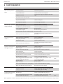
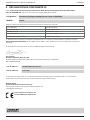
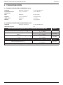
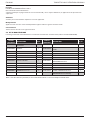
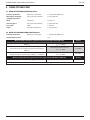
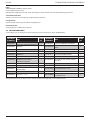
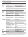
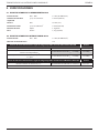
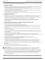
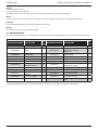
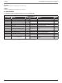
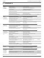
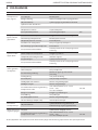
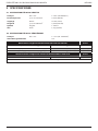
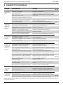
2. SPECIFICATIONS
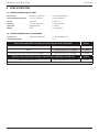
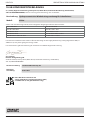
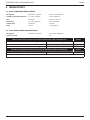
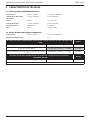
2.1 SPECIFICATION FOR 07536 TOOL
Air Pressure Minimum - Maximum 5-7 bar (70-100 lbf/in2)
Free Air Volume Required @ 5.1 bar /75 lbf/in22.6 litres (0.09 ft3)
Stroke Minimum 25 mm (1 in)
Pull Force @ 5.5 bar /80 lbf/in23.89 kN (875 lbf)
Cycle time Approximately 1 second
Weight Pistol 1.2 kg (2.64 lb)
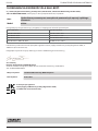
2.2 SPECIFICATION FOR 07531 INTENSIFIER
Air Pressure Minimum - Maximum 5-7 bar (70-100 lbf/in)
Intensication Ratio 32:1
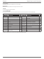
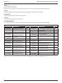
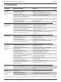
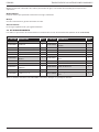
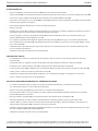
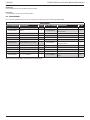
Noise values determined according to noise test code ISO 15744 and ISO 3744. 07536
A-weighted sound power level dB(A), LWA Uncertainty noise: kWA = 2.3 dB(A) 79.5 dB(A)
A-weighted emission sound pressure level at the work station
dB(A), LpA
Uncertainty noise: kpA = 2.3 dB(A) 68.5 dB(A)
C-weighted peak emission sound pressure level dB(C), LpC, peak Uncertainty noise: kpC = 2.5 dB(C) 96.9 dB(C)
Vibration values determined according to vibration test code ISO 20643 and ISO 5349. 07536
Vibration emission level, ahd:Uncertainty vibration: k = 0.25 m/s 0.97 m/s
Declared vibration emission values in accordance with EN 12096
7
ORIGINAL INSTRUCTION ENGLISH

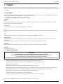
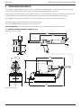
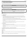
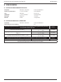
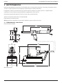
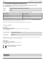
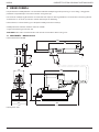
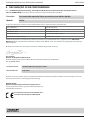
3. INTENT OF USE
The pneumatic 07536 tool is a hand held light weight tool designed to place 1/16” Avlug® making it ideal for batch or ow-
line assembly in a wide variety of applications throughout all industries.
The Hand Tool and Intensier have been tested as separate items and combined. They must only be used together and for
no other purposes. Refer to "Putting into Service" on page 9-12 for connection details.
Part numbers are shown to order a complete tool but no nose equipment.
The tool number for the 07536 model is 07536-02200.
See the general assemblies on pages 15-22.
DO NOT use under wet conditions or in the presence of ammable liquids or gases.
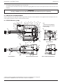
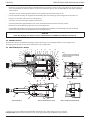
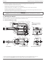
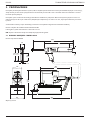
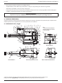
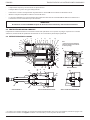
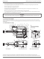
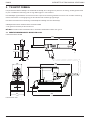
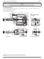
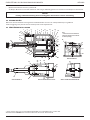
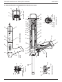
3.1 TOOL DIMENSIONS - 07536 MODEL
Part Number 07536-02100
0753
60
2.36
28
1.10
98
3.85
130
5.12
475
18.70 338
13.30
51
2
163
6.41
140
5.51
54
2.12
201
7.91
420
16.54
333
01.31
502
19.76
Dimensions in mm.
8
ENGLISH ORIGINAL INSTRUCTION

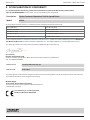
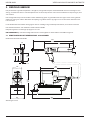
4. PUTTING INTO SERVICE
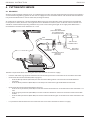
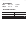
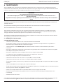
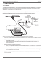
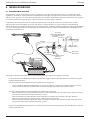
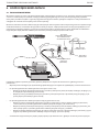
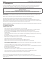
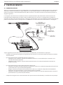
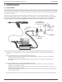
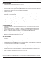
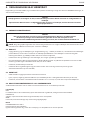
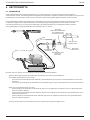
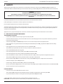
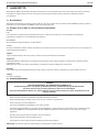
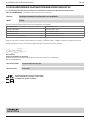
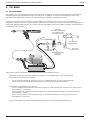
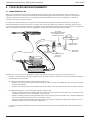
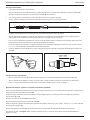
4.1 AIR SUPPLY
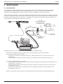
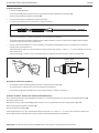
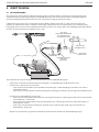
All tools are operated with compressed air at an optimum pressure of 5.5 bar. We recommend the use of pressure regulators
and automatic oiling/ltering systems on the main air supply. To ensure maximum tool life and minimum tool maintenance
they should be tted within 3 metres of the tool (see diagram below).
Air supply hoses should have a minimum working eective pressure rating of 150% of the maximum pressure produced
in the system or 10 bar, whichever is the highest. Air hoses should be oil resistant, have an abrasion resistant exterior and
should be armoured where operating conditions may result in hoses being damaged. All air supply hoses MUST have a
minimum bore diameter of 6.4 millimetres or / inch.
8
6
4
2
0
10
12
41
16
TAKE OFF POINT
FROM MAIN SUPPLY
STOP COCK
(USED DURING MAINTENANCE
OF FILTER/REGULATOR
OR LUBRICATION UNITS)
MAIN SUPPLY
DRAIN POINT
PRESSURE REGULATOR
AND FILTER
(DRAIN DAILY)
3
M
E
T
R
E
S
M
A
X
I
M
U
M
AIR LUBRICATION
PERMISSABLE
0753
TYPE
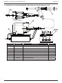
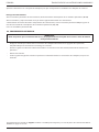
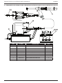
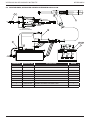
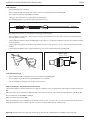
Follow the steps below when connecting the tool to the intensier and main air supply:
• Push the end of the large hydraulic hose from the tool into the quick release connector on the end of the intensier.
• On the front face of the intensier (Refer to page 15):
• Push the blue pneumatic (4mm OD) line into the reducer tting which is located in the left hand bulkhead
connector.
• Push the black pneumatic (4mm OD) line into the plastic collet of the right hand bulkhead connector.
• On the front face of the control box (Refer to page 15):
• Push the silver pneumatic (3mm OD) line into the reducer labelled ‘Cursor’ on the front face of the control box - LH
side.
• Push the green pneumatic (4mm OD) line into the reducer labelled ‘Tail Jaws’ on the front face of the control box -
middle.
• Push the white pneumatic (4mm OD) line into the reducer labelled ‘Signal’ on the front face of the control box - RH
side.
• Fit a pneumatic hose between the male connector at the rear of the intensier and main air supply.
9
ORIGINAL INSTRUCTION ENGLISH

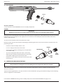
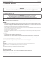
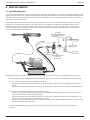
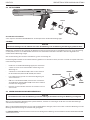
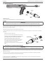
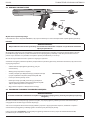
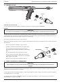
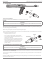
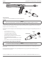
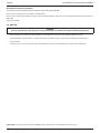
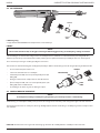
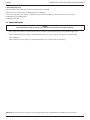
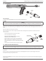
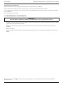
4.2 AIR CURSORS
0753
TYPE
TOOL
BARREL
CURSOR
NOSE
JAWS
Air Cursor Selection
See separate data sheet 07900-00863 for nose assembly components.
CURSOR
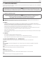
IMPORTANT
If tted incorrectly, the cursor will not allow the loading of the tool and feeding of the fasteners.
While the cursor will be tted the correct way round when the tool is supplied, we recommend that you check its orientation
before tting the nose equipment. The slightly concave end of the cursor should point towards the front of the tool as
shown in the illustration.
To reverse the orientation of the cursor, follow these steps:
Extreme caution must be exercised whe undertaking the following procedure. Care must be taken to avoid the barrel and
protruding mandrel.
• Remove the Nose Assembly if there is one.
• Insert an empty mandrel fully into the tool.
• Close the Tail Jaws 32, by switching on the tail jaw switch
(items 18 and 19).
• The cursor will pop out of the barrel after a short delay.
• Open the Tail Jaws 32, by switching o the tail jaw switch
(items 18 and 19), this will release the mandrel.
• Remove the cursor from the mandrel and insert the cursor
into the barrel.
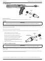
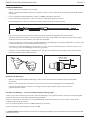
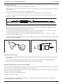
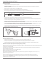
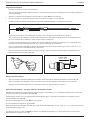
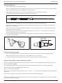
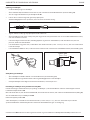
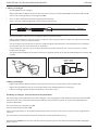
4.3 LOADING AND RELOADING THE TOOL
IMPORTANT
The procedure for loading the tool and for tting the nose equipment to the tool is integral.
When ordering a complete tool or system you will normally be supplied with all the nose equipment required for the
fastener to be placed.
If you have been supplied with a nose jaw, mandrels and mandrel follower springs proceed with loading the tool and tting
the nose equipment as shown below.
TOOL
BARREL
CURSOR
CONCAVE END
NOSE
JAWS
Item numbers in bold refer to the general assembly and parts list for the 07536-02200 Tool on pages 18-19.
10
ENGLISH ORIGINAL INSTRUCTION

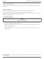
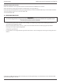
Loading the Tool
• Connect the air supply to the tool.
• Open Tail Jaws 32 which grip the mandrel, by switching o the tail jaw switch (items 18 and 19).
• Screw selected nose jaws onto Barrel 44 of the tool.
•* Insert a mandrel into the tail end of the fasteners through the paper pod.
• Slide the mandrel follower spring onto the mandrel ensuring correct orientation.
• Gripping the tail end of the mandrel, tear o the paper pod from around the fasteners.
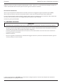
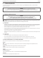
• Open the nose jaws either by rotating the outer ring on Cam operated jaws or by pushing outwards on the jaw ends, as
illustrated below left.
• Insert the previously assembled mandrel, mandrel follower spring and fasteners into the nose jaws until the rst
fastener to be placed is protruding from the nose jaw.
• Close the nose jaws and adjust so that the rst fastener protrudes by 1.5mm - 3mm (/” to /”), as shown in the
illustration below right.
• Close the Tail Jaws 32 to ensure the mandrel is gripped, by switching on the tail jaw switch (items 18 and 19).
1.5mm - 3mm
(1/16 " - 1/8 ")
Re-loading the Tool
• Open Tail Jaws 32 of tool, by switching o the tail jaws (items 18 and 19).
• Open the nose jaws and pull the empty mandrel and mandrel follower spring out of the tool.
• Reload the tool by following the above instructions, starting at stage •*.
Setting the Tool - Adjustable Nose Assemblies Only
Insert the previously assembled mandrel (see Loading the Tool •*) or the disposable mandrel against the stop within the Tail
Jaw Piston Assembly 60.
While holding the mandrel, close the Tail Jaws 32, which grip the mandrel, by switching on the tail jaw switch (18 and 19).
Screw the lock nut onto the Barrel 44 of the tool.
Rotate the nose assembly onto the Barrel 44.
Adjust the nose assembly so that the rst fastener protrudes by 1,5mm-3mm (/”-/”), as shown in the illustration on page 11.
Tighten the lock nut against the nose assembly to prevent the nose jaw assembly from moving.
Item numbers in bold refer to the general assembly and parts list for the 07536-02200 Tool on pages 18-19.
11
ORIGINAL INSTRUCTION ENGLISH

Re-loading the Tool
Open the tail jaws of the tool, by switching o the tail jaw switch (18-19).
Open the jaws and pull the empty mandrel and follower spring out of the tool.
Insert the new mandrel against the stop within the too, and close the Tail Jaws 32 which grip the mandrel, by switching on
the tail jaw switch (18 and 19).
Close the Tail Jaws 32.
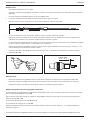
4.4 OPERATING PROCEDURE
IMPORTANT
You must check that the cursor orientation and the nose equipment are correct before attempting to operate the tool.
• Push the fastener, protruding from the nose jaws, fully into the application holes ensuring that the tool is held square.
• Operate the trigger without releasing - the mandrel head is pulled through the fastener, forming the fastener into the
application.
• Remove the tool.
• Release the trigger. The next fastener will be automatically presented through the nose jaws, ready for placing.
Item numbers in bold refer to the general assembly and parts list for the 07536-02200 Tool on pages 18-19.
12
ENGLISH ORIGINAL INSTRUCTION

5. SERVICING THE TOOL
Regular servicing should be carried out and a comprehensive inspection performed annually or every 500,000 cycles,
whichever is sooner.
IMPORTANT
The employer is responsible for ensuring that tool maintenance instructions are given to the appropriate personnel.
The operator should not be involved in maintenance or repair of the tool unless properly trained.
5.1 PNEUMATIC CONTROL BOX
IMPORTANT
Under no circumstances must the pneumatic box be opened. The box is a closed item.
The internal adjustments are preset and must not be altered or tampered with.
Only Authorised STANLEY Engineered Fastening personnel may dismantle this control box.
CAUTION: Never use solvents or other harsh chemicals for cleaning the non-metallic parts of the tool. These chemicals
may weaken the materials used in these parts.
5.2 DAILY
• Daily, before use or when rst putting the tool into service. Pour a few drops of clean lubricating oil into the air inlet of
the intensier if no lubricator is tted on air supply. If the tool is in continuous use, the air hose should be disconnected
from the main air supply and the tool lubricated every two to three hours.
• Check for air and oil leaks. If damaged, hoses and couplings should be replaced.
• If there is no lter on the pressure regulator, bleed the airline to clear it of accumulated dirt or water before connecting
the air hose to the intensier. If there is a lter, drain it.
• Check that the nose equipment is correct.
• Check mandrels regularly for signs of wear or damage monitoring the number of placings (read the safety instructions
on page 4-6).
5.3 WEEKLY
• Conduct the full “Daily” procedures as described above.
• Remove, inspect, clean and grease the Tail Jaws (refer to “Tail Jaw Cylinder” in the "Maintenance Section" page 16).
• Check oil level in the intensier Unit reservoir is approximately 12mm (1/2”) below the transparent cover plate.
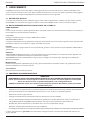
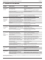
5.4 MOLY LITHIUM GREASE EP 3753 SAFETY DATA
Grease can be ordered as a single item, the part number is shown in the Service Kit page 14.
First Aid
SKIN:
As the grease is completely water resistant it is best removed with an approved emulsifying skin cleaner.
INGESTION:
Ensure the individual drinks 30ml Milk of Magnesia, preferably in a cup of milk.
EYES:
Irritant but not harmful. Irrigate with water and seek medical attention.
Fire
FLASH POINT: Above 220°C.
Not classied as ammable.
Suitable extinguishing media: CO2, Halon or water spray if applied by an experienced operator.
Environment
Scrape up for burning or disposal on approved site.
13
ORIGINAL INSTRUCTION ENGLISH

Handling
Use barrier cream or oil resistant gloves.
Storage
Away from heat and oxidising agent.
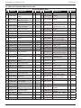
5.5 SERVICE KIT
For all servicing we recommend the use of the Service Kit (part number 07900-05300).
SERVICE KIT
ITEM PART Nº DESCRIPTION Nº OFF ITEM PART Nº DESCRIPTION Nº OFF
07900-00157 CIRCLIP PLIERS 1 07900-00352 SEAL REMOVAL HOOK 1
07900-00006 SPATULA 1 07900-00710 BARREL PLUG REMOVAL SPAN-NER 1
07900-00446 EXTRACTOR 1 07900-00725 BULLET 1
07900-00603 BARREL VICE JAWS 1 07900-00243 SCREWDRIVER 1
07900-00520 /" ROD 1 07900-00717 INTENSIFIER SPANNER 1
07900-00521 /" ROD 1 07900-00013 /" ALLEN KEY 1
07900-00602 'O' RING ASSEMBLY BULLET 1 07900-00617 LOCTITE® MULTI-GASKET 574 50ml PACK 1
07900-00595 18mm SPANNER 1 07900-00469 2.5mm ALLEN KEY 1
07900-00434 32mm SPANNER 1 07900-00351 3mm ALLEN KEY 1
07900-00237 /" × /" B.S.W. SPANNER 1 07900-00224 4mm ALLEN KEY 1
07900-00012 /" × /" SPANNER 1 07900-00225 5mm ALLEN KEY 1
07900-00008 /" × 1/2" SPANNER 1 07992-00020 80g TIN MOLY LITHIUM GREASE EP 3753 1
Note: Spanner sizes are measured 'across ats' unless otherwise specied.
14
ENGLISH ORIGINAL INSTRUCTION

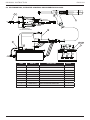
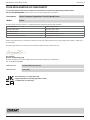
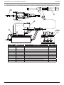
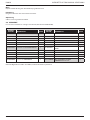
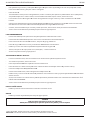
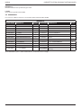
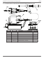
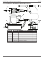
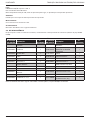
5.6 AIR CURSOR TOOL, INTENSIFIER & CONTROL BOX ASSEMBLY 07536-02100
4 5
9
2
6
3
7 8
1
BLUE PIPE
BLACK PIPE
PART SECTION 'A-A'
(PROTECTION PLATE REMOVED)
AA
CURSOR
TAIL JAWS
SIGNAL
SILVER
PIPE
GREEN
PIPE
WHITE
PIPE
ITEM PART No DESCRIPTION No OFF
1 07536-02200 AIR CURSOR HAND TOOL 1
2 07531-02200 INTENSIFIER TOOL 1
3 07007-02024 AIR CURSOR CONTROL BOX 1
4 07005-10071 T CONNECTOR 1
5 07005-10072 8 MM TUBING (2.50 m) 1
6 74405-12080 MODIFIED M8 NUTSERT 8
7 07001-00469 M8 × 15 SOCKET CAP HEAD SCREW 2
8 07002-00105 M8 WASHER 4
9 07005-01573 MALE CONNECTOR 8MM TUBE 1
10 07005-01977 MALE/FEMALE REDUCER 6MM /4MM 1
15
ORIGINAL INSTRUCTION ENGLISH

6. MAINTENANCE
Every 500,000 cycles the tool should be completely dismantled and new components should be used where worn, damaged
or when recommended. All ‘O’ rings and seals should be renewed and lubricated with Moly Lithium grease EP 3753 before
assembling.
IMPORTANT
Safety Instructions appear on page 4.
The employer is responsible for ensuring that tool maintenance instructions are given to the appropriate personnel.
The operator should not be involved in maintenance or repair of the tool unless properly trained.
The airline must be disconnected before any servicing or dismantling is attempted, unless specically instructed otherwise.
It is recommended that any dismantling operation be carried out in clean conditions.
Prior to dismantling the tool, you will need to remove the nose equipment.
For total tool servicing we advise that you proceed with the dismantling of sub-assemblies in the order shown below
after having disconnected the hydraulic hose from the intensier unit, air lines from the intensier and control box, thus
separating the pistol unit from the intensier unit.
The potentially dangerous substances that could have deposited on the machine as a result of work processes must be
removed before maintenance.
6.1 DISMANTLING 07536-02200
TAIL JAW CYLINDER
• Manually ip the retaining Clip 53 up and remove the End Cap 59.
• Using an Allen Key*, remove one Cap Head Screw 6 ensuring that any trapped air in the tail jaw cylinder is exhausted.
Remove the second Cap Head Screw 6.
• Pull out Rear Plug 50. Note: To aid extraction there is a 5mm thread on the rear face of the plug.
• Extract air tail jaw components, comprising Tail Jaw Piston Assembly 60, Stop 52, ‘O’ Ring 12 and Jaws 32.
• Extract the remaining components, comprising of Spring 36 and Jaw Housing 42.
• Free length of spring 36 should be 38.1mm (1.5”). Replace if necessary.
• Remove piston assembly seal ‘O’ Ring 11.
• Disconnect Air Cursor Concertina Tube (Green) 49 from Elbow Connector 22.
• Disconnect Air Cursor Concertina Tube (Silver) 38 from Barb Elbow 30.
• Using an Allen Key*, remove all ve handle moulding securing Screws 3, 4 and all four Nuts 8 from the tool handle.
• Grip Barrel 44 in a vice using soft jaws* to avoid damage.
• Using a box spanner*, unscrew Barrel Plug 46, preventing Barrel 44 turning by using an open ended spanner*.
• Pull the Tail Jaw Cylinder 47 from the tool.
• Remove ‘O’ Ring 14, Rubbing Strip 41 and Barrel Return Spring 37.
• Coat the face of Tail Jaws 32 with Moly Lithium grease, in contact with Jaw Housing 42, before assembling.
• Assemble in reverse order of dismantling.
HYDRAULIC PISTON
• Remove Tail Jaw Cylinder 47 as described earlier.
• Grip Body 45 in vice using soft jaws* to avoid damage, undo Stroke Limiter 40.
• Using an Allen Key*, loosen Screw 5 that is clamping the Switch Block 54 to the barrel 44.
* Refers to items included in the 0753 Mkll Service Kit. For complete list see page 14.
Item numbers in bold refer to the general assemblies and parts lists on pages 18-19.
16
ENGLISH ORIGINAL INSTRUCTION

• Hold the tool rmly and pull the Barrel 44 from the Body 45 (a small quantity of hydraulic oil may be ejected from inside
the head assembly).
• Remove Piston 39 carefully so as not to damage head bore.
• Remove Seal 16.
• Seal 17 is dicult to remove without damaging, but can remain in place during cleaning (provided it is not aected by
cleaning process). If however, Seal 17 requires renewing proceed as follows:
• Using spatula*, prise out Seal 17 from Body 45, taking care not to damage body cavity and bores. The removed Seal 17
MUST be discarded.
• To replace Seal 17, unscrew Bleed Plug Assembly 43 until inside face is level with internal bore of the Body 45. This will
provide a smooth passage for insertion of a new Seal 17 through rear of Body 45.
• Ensure the Seal 17 is well greased and the correct way round with the open end of the seal facing the rear tail jaws.
• Complete assembly in reverse order of dismantling.
TRIGGER ASSEMBLY
• To dismantle/service assembly, remove covers from the tool as described earlier.
• Disconnect all air hoses from assembly, taking care not to damage them. Remove assembly.
• Using a spanner*, unscrew the Retainer 34 and remove. Take care to keep the Spring 31.
• Prise o the ‘O’ Ring 10 taking care not to damage the Spindle 35 and Retainer 34 seatings.
• Clean and re-assemble using a new ‘O’ Ring 10.
• Check length of Spring 31 which must be 12.7mm (0.5”) free length – replace if necessary.
• Assembly in reverse order of dismantling.
TAIL JAW ON/OFF VALVE
• The unit is designed so that minimum of servicing is required during the life of the tool.
• If it is necessary to dismantle the valve, proceed as follows:
• Remove Trigger Housing 56 as described in section “Hydraulic Piston”.
• Using a screwdriver*, carefully remove the Chrome Star-lock Washer 18 from Air Tail Jaw Spool 55 and discard washer.
• Extract Air Tail Jaw Spool 55 from Switch Block 54.
• Taking care not to damage the Air Tail Jaw Spool 55, remove the ‘O’ Rings 12.
• Clean spool and ret new ‘O’ Rings 12 using assembly bullet* and insert into Switch Block 54, noting its orientation.
• Fit New Chrome Star-lock Washer 18 by clamping in a soft jaw vice to prevent damage. DO NOT USE UNDUE FORCE.
• Complete assembly in reverse order of dismantling.
HANDLE & END CAP
• Clean and inspect mouldings for cracks or other damage.
CURSOR
• Clean and oil cursor assembly occasionally with a little light oil.
IMPORTANT
Check the tool against daily and weekly servicing.
Priming is ALWAYS necessary after the tool has been dismantled and prior to operating.
* Refers to items included in the 0753 Mkll Service Kit. For complete list see page 14.
Item numbers in bold refer to the general assemblies and parts lists on pages 18-19.
17
ORIGINAL INSTRUCTION ENGLISH

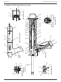
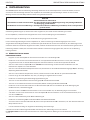
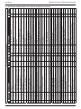
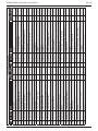
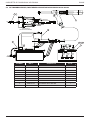
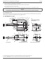
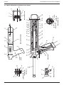
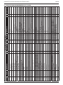
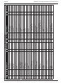
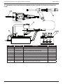
6.2 GENERAL ASSEMBLY OF BASE TOOL 07536-02200
8
4
8
4
4
8
8
3
8
3
48
HANDLE COVER DETAILS
WW
14
44
25
17 6445 37 3242
1211
11
V
V
15
16 45 47 60
39 41 33 49
36
2
(GREEN PIPE) (SILVER PIPE)
52
38
40
29
20
24
PART SECTION 'W'-'W'
PART SECTION 'V'-'V'
6
9
69
53
X
X
TRIGGER VALVE DETAIL
35
26
21
34 31
56
10
50
13
28 27
59
57 RH
58 LH
43
11
5
51
18
SECTION 'X'-'X'
55
19
12
22 (BLUE PIPE)
22 (WHITE PIPE)
(BLACK PIPE)
WW
61
30, 38
22, 49
2
2
18
ENGLISH ORIGINAL INSTRUCTION

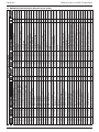
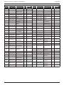
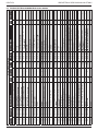
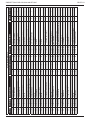
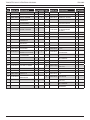
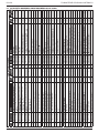
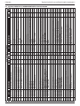
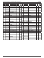
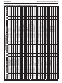
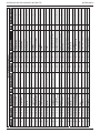
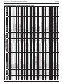
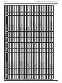
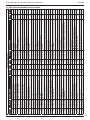
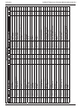
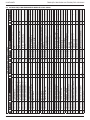
6.3 PARTS LIST FOR BASE TOOL 07536-02200
07536-02200 PARTS LISTS
ITEM PART N° DESCRIPTION QTY SPARES ITEM PART N° DESCRIPTION QTY SPARES
1 07007-00392 CABLE TIE (NOT SHOWN) 1 - 34 07220-00803 RETAINER 1 -
2 07001-00499 M3×5 LONG SOCKET SET
SCREW 3 - 35 07241-00208 SPINDLE 1 -
3 07001-00262 M4×22 LONG SOCKET
HEAD CAP SCREW 1 - 36 07154-00404 SPRING 1 -
4 07001-00401 M4×10 LONG SOCKET
HEAD CAP SCREW 4 - 37 07490-03002 BARREL RETURN SPRING 1 -
5 07001-00404 M5×6 LONG SOCKET
HEAD SET SCREW 1 - 38 07536-02211 3MM AIR CURSOR CON-
CERTINA TUBE - SILVER 1 -
6 07001-00504 M4×6 LONG SOCKET
HEAD CAP SCREW 2 2 39 07536-00203 PISTON 1 -
7 40 07530-00204 STROKE LIMITER 1 -
8 07002-00134 M4 HEX NUT 4 - 41 07530-00206 RUBBING STRIP 1 1
9 07002-00153 M4 WASHER [PLASTIC] 2 - 42 07536-00208 JAW HOUSING 1 -
10 07003-00022 'O' RING 1 - 43 07530-00500 BLEED PLUG ASSEMBLY
[ITEMS 62 TO 65] 1 -
11 07003-00113 'O' RING 3 3 44 07536-02201 BARREL 1 -
12 07003-00121 'O' RING 3 3 45 07530-02202 BODY 1 -
13 07003-00142 1/8" BSP BONDED SEAL 1 1 46 07530-02205 BARREL PLUG 1 -
14 07003-00167 'O' RING 1 1 47 07536-02207 TAIL JAW CYLINDER 1 -
15 07003-00386 'O' RING 2 - 48 07530-02210 LABEL 2 -
16 07003-00236 SEAL [DYNAMIC] 1 1 49 07536-02212 4MM AIR CURSOR CON-
CERTINA TUBE - GREEN 1 -
17 07003-00237 SEAL [STATIC] 1 - 50 07536-02213 REAR PLUG 1 -
18 07004-00058 1/8" STARLOCK WASHER
CHROME 1 - 51 07530-00310 BLANKING PLUG 2 -
19 07004-00059 1/8" STARLOCK WASHER
BLACK 1 - 52 07536-02214 STOP 1 -
20 07005-10073 3MM CONNECTOR 1 - 53 07530-02220 CLIP 1 -
21 07005-01357 COLLET TYPE CON-
NECTOR 1 - 54 07530-02301 SWITCH BLOCK 1 -
22 07005-01571 ELBOW CONNECTOR 3 - 55 07530-02302 AIR TAIL JAW SPOOL 1 -
23 07536-02216 LOCKNUT 1 - 56 07530-02311 TRIGGER HOUSING 1 -
24 07005-10074 2MM CONNECTOR 1 - 57 07536-02601 HANDLE MOULDING AS-
SEMBLY RIGHT HAND 1 -
25 07007-00017 DUST CAP 1 - 58 07536-02602 HANDLE MOULDING AS-
SEMBLY LEFT HAND 1 -
26 07007-00300 TRIGGER BUTTON 1 - 59 07530-02603 END CAP 1 -
27 73200-02022 SAFETY LABEL 1 - 60 07536-02800 TAIL JAW PISTON ASSEM-
BLY 1 -
28 07007-01504 CE MARK LABEL 1 - 61 07536-02215 FITTING ADAPTER 1 -
29 07008-00438 FLEXIBLE HOSE ASSEM-
BLY 1 - 62 07003-00142 BONDED SEAL (NOT
SHOWN) 1 1
30 07005-01323 M3 BARB ELBOW 1 - 63 07003-00194 BONDED SEAL (NOT
SHOWN) 1 1
31 07125-00215 SPRING 1 - 64 07001-00442 SCREW (NOT SHOWN) 1 1
32 07151-00403 TAIL JAWS 1
pair 2 65 07530-00501 PLUG (NOT SHOWN) 1 -
33 07003-00016 'O' RING 1
19
ORIGINAL INSTRUCTION ENGLISH

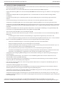
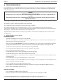
6.4 DISMANTLING INSTRUCTIONS
• When dismantling the intensier assembly, rst disconnect the air supply hose to intensier inlet Connector 22.
• Using an Allen Key* undo four Screws 27 and remove Protection Plate 24.
• Disconnect the trigger hose 47 from the intensier Valve 43 or 48 by depressing the outlet collet and withdrawing the hose.
• Remove Cover Plate 4 and Gasket 35 by removing Screws 37 and Washers 36 using Allen Key*.
• Ensure that gasket is not damaged to ensure a proper seal on assembly.
• Invert intensier assembly and drain oil from reservoir into a suitable container.
• Remove Quick Release Connector 32 together with Connector 31 and Seals 33 with suitable spanner*.
• Remove intensier Valve 43 or 48 by removing the xing screws with a suitable spanner taking care to retain ‘O’ Ring 21
located in the Intensier Body Casting.
• Remove Screw 19 using a suitable Allen Key* and remove Silencer Cover 16, Foam Silencer 15, Spacer 18 and Retaining
Plate 20.
• Pull o the 6mm Plastic Tube 41 from Vacuum Connectors 42.
• From the base of the intensier insert a 3mm Allen Key * through the two holes and unscrew the Vacuum Connectors
42. Note:
• Care must be taken as the vacuum connectors are locked and sealed in place using Loctite® 574.
• If dicult to remove, the vacuum connectors can be drilled out using a /” or 4.7mm diameter drill.
• To reassemble the Vacuum Connectors 42, the following procedure must be followed: -
• Soak the vacuum connectors in a suitable primer, i.e. Perma Bond A905
• Place a drop of Loctite® 574 in the intensier threaded hole.
• From the base of the intensier insert the Allen Key * through the hole. Ensure that the Allen Key * is free from
Loctite® 574 before inserting into the vacuum connector.
• Rotate the Allen Key while applying Loctite® 574 to the base of the vacuum connector.
• Screw the Vacuum connector into the intensier, ensuring that there is sucient Loctite® 574 at the base of the
tting such the thread is not visible.
• Using a screwdriver, carefully remove internal Retaining Ring 14. Clean and inspect groove for sign of damage.
• Using Extractor*, insert male threaded end into End Cover 12 and withdraw it along with intensier Sleeve 28 and ‘O’
Rings 10 and 13.
• Insert Rod* through the connector orice at the front of the intensier body and tap out Piston Rod 9 and Piston
Assembly.
• Using a suitable Allen Key*, unscrew two Screws 25 and remove End Cover 12 from intensier Sleeve 28.
• Remove Seal Plug 7 with spanner*.
• Insert rod* through connector orice at the front of the intensier body and push out Seal Housing 5 and associated ‘O’
rings and lip seals.
• Remove Valve Housing Assembly 34 from the main body with a suitable spanner*. Clean by blowing through with a
low-pressure air jet.
• Remove Piston Rod 9 from intensier Air Piston 11 by gripping the rst 20 mm (3/4”) of the rod in a vice tted with soft
jaws, taking care not to damage or mark the working surface.
• Unscrew locking Nut 17 with a suitable spanner*.
• Assemble in the reverse order of dismantling, observing the following:
• Clean all parts and renew all ‘O’ rings.
• Lubricate all seals using Moly Lithium grease.
• Valve Housing Assembly 34 must be retted using a thread sealing adhesive.
* Refers to items included in the 0753 MkII Service Kit. For complete list see page 14.
Item numbers in bold refer to the illustration and parts list opposite.
20
ENGLISH ORIGINAL INSTRUCTION
Sidan laddas...
Sidan laddas...
Sidan laddas...
Sidan laddas...
Sidan laddas...
Sidan laddas...
Sidan laddas...
Sidan laddas...
Sidan laddas...
Sidan laddas...
Sidan laddas...
Sidan laddas...
Sidan laddas...
Sidan laddas...
Sidan laddas...
Sidan laddas...
Sidan laddas...
Sidan laddas...
Sidan laddas...
Sidan laddas...
Sidan laddas...
Sidan laddas...
Sidan laddas...
Sidan laddas...
Sidan laddas...
Sidan laddas...
Sidan laddas...
Sidan laddas...
Sidan laddas...
Sidan laddas...
Sidan laddas...
Sidan laddas...
Sidan laddas...
Sidan laddas...
Sidan laddas...
Sidan laddas...
Sidan laddas...
Sidan laddas...
Sidan laddas...
Sidan laddas...
Sidan laddas...
Sidan laddas...
Sidan laddas...
Sidan laddas...
Sidan laddas...
Sidan laddas...
Sidan laddas...
Sidan laddas...
Sidan laddas...
Sidan laddas...
Sidan laddas...
Sidan laddas...
Sidan laddas...
Sidan laddas...
Sidan laddas...
Sidan laddas...
Sidan laddas...
Sidan laddas...
Sidan laddas...
Sidan laddas...
Sidan laddas...
Sidan laddas...
Sidan laddas...
Sidan laddas...
Sidan laddas...
Sidan laddas...
Sidan laddas...
Sidan laddas...
Sidan laddas...
Sidan laddas...
Sidan laddas...
Sidan laddas...
Sidan laddas...
Sidan laddas...
Sidan laddas...
Sidan laddas...
Sidan laddas...
Sidan laddas...
Sidan laddas...
Sidan laddas...
Sidan laddas...
Sidan laddas...
Sidan laddas...
Sidan laddas...
Sidan laddas...
Sidan laddas...
Sidan laddas...
Sidan laddas...
Sidan laddas...
Sidan laddas...
Sidan laddas...
Sidan laddas...
Sidan laddas...
Sidan laddas...
Sidan laddas...
Sidan laddas...
Sidan laddas...
Sidan laddas...
Sidan laddas...
Sidan laddas...
Sidan laddas...
Sidan laddas...
Sidan laddas...
Sidan laddas...
Sidan laddas...
Sidan laddas...
Sidan laddas...
Sidan laddas...
Sidan laddas...
Sidan laddas...
Sidan laddas...
Sidan laddas...
Sidan laddas...
Sidan laddas...
Sidan laddas...
Sidan laddas...
Sidan laddas...
Sidan laddas...
Sidan laddas...
Sidan laddas...
Sidan laddas...
Sidan laddas...
Sidan laddas...
Sidan laddas...
Sidan laddas...
Sidan laddas...
Sidan laddas...
Sidan laddas...
Sidan laddas...
Sidan laddas...
Sidan laddas...
Sidan laddas...
Sidan laddas...
Sidan laddas...
Sidan laddas...
Sidan laddas...
Sidan laddas...
Sidan laddas...
Sidan laddas...
Sidan laddas...
Sidan laddas...
Sidan laddas...
Sidan laddas...
Sidan laddas...
Sidan laddas...
Sidan laddas...
Sidan laddas...
Sidan laddas...
Sidan laddas...
Sidan laddas...
Sidan laddas...
Sidan laddas...
Sidan laddas...
Sidan laddas...
Sidan laddas...
Sidan laddas...
Sidan laddas...
Sidan laddas...
Sidan laddas...
Sidan laddas...
Sidan laddas...
Sidan laddas...
Sidan laddas...
Sidan laddas...
Sidan laddas...
Sidan laddas...
Sidan laddas...
Sidan laddas...
Sidan laddas...
Sidan laddas...
Sidan laddas...
Sidan laddas...
Sidan laddas...
Sidan laddas...
Sidan laddas...
Sidan laddas...
Sidan laddas...
Sidan laddas...
Sidan laddas...
Sidan laddas...
Sidan laddas...
Sidan laddas...
Sidan laddas...
Sidan laddas...
Sidan laddas...
Sidan laddas...
Sidan laddas...
Sidan laddas...
Sidan laddas...
Sidan laddas...
Sidan laddas...
Sidan laddas...
Sidan laddas...
Sidan laddas...
Sidan laddas...
Sidan laddas...
Sidan laddas...
Sidan laddas...
Sidan laddas...
Sidan laddas...
Sidan laddas...
Sidan laddas...
Sidan laddas...
Sidan laddas...
Sidan laddas...
Sidan laddas...
Sidan laddas...
Sidan laddas...
Sidan laddas...
Sidan laddas...
Sidan laddas...
Sidan laddas...
Sidan laddas...
Sidan laddas...
Sidan laddas...
Sidan laddas...
Sidan laddas...
Sidan laddas...
Sidan laddas...
Sidan laddas...
Sidan laddas...
Sidan laddas...
Sidan laddas...
Sidan laddas...
Sidan laddas...
Sidan laddas...
Sidan laddas...
Sidan laddas...
Sidan laddas...
Sidan laddas...
Sidan laddas...
Sidan laddas...
Sidan laddas...
Sidan laddas...
Sidan laddas...
Sidan laddas...
Sidan laddas...
Sidan laddas...
Sidan laddas...
Sidan laddas...
Sidan laddas...
Sidan laddas...
Sidan laddas...
Sidan laddas...
Sidan laddas...
Sidan laddas...
Sidan laddas...
Sidan laddas...
Sidan laddas...
Sidan laddas...
Sidan laddas...
Sidan laddas...
Sidan laddas...
Sidan laddas...
Sidan laddas...
Sidan laddas...
Sidan laddas...
Sidan laddas...
Sidan laddas...
Sidan laddas...
Sidan laddas...
Sidan laddas...
Sidan laddas...
Sidan laddas...
Sidan laddas...
Sidan laddas...
Sidan laddas...
Sidan laddas...
Sidan laddas...
Sidan laddas...
Sidan laddas...
Sidan laddas...
Sidan laddas...
Sidan laddas...
Sidan laddas...
Sidan laddas...
Sidan laddas...
Sidan laddas...
Sidan laddas...
Sidan laddas...
Sidan laddas...
Sidan laddas...
Sidan laddas...
Sidan laddas...
Sidan laddas...
Sidan laddas...
Sidan laddas...
Sidan laddas...
Sidan laddas...
Sidan laddas...
Sidan laddas...
Sidan laddas...
Sidan laddas...
Sidan laddas...
Sidan laddas...
Sidan laddas...
Sidan laddas...
Sidan laddas...
Sidan laddas...
Sidan laddas...
Sidan laddas...
Sidan laddas...
Sidan laddas...
Sidan laddas...
Sidan laddas...
Sidan laddas...
Sidan laddas...
Sidan laddas...
-
 1
1
-
 2
2
-
 3
3
-
 4
4
-
 5
5
-
 6
6
-
 7
7
-
 8
8
-
 9
9
-
 10
10
-
 11
11
-
 12
12
-
 13
13
-
 14
14
-
 15
15
-
 16
16
-
 17
17
-
 18
18
-
 19
19
-
 20
20
-
 21
21
-
 22
22
-
 23
23
-
 24
24
-
 25
25
-
 26
26
-
 27
27
-
 28
28
-
 29
29
-
 30
30
-
 31
31
-
 32
32
-
 33
33
-
 34
34
-
 35
35
-
 36
36
-
 37
37
-
 38
38
-
 39
39
-
 40
40
-
 41
41
-
 42
42
-
 43
43
-
 44
44
-
 45
45
-
 46
46
-
 47
47
-
 48
48
-
 49
49
-
 50
50
-
 51
51
-
 52
52
-
 53
53
-
 54
54
-
 55
55
-
 56
56
-
 57
57
-
 58
58
-
 59
59
-
 60
60
-
 61
61
-
 62
62
-
 63
63
-
 64
64
-
 65
65
-
 66
66
-
 67
67
-
 68
68
-
 69
69
-
 70
70
-
 71
71
-
 72
72
-
 73
73
-
 74
74
-
 75
75
-
 76
76
-
 77
77
-
 78
78
-
 79
79
-
 80
80
-
 81
81
-
 82
82
-
 83
83
-
 84
84
-
 85
85
-
 86
86
-
 87
87
-
 88
88
-
 89
89
-
 90
90
-
 91
91
-
 92
92
-
 93
93
-
 94
94
-
 95
95
-
 96
96
-
 97
97
-
 98
98
-
 99
99
-
 100
100
-
 101
101
-
 102
102
-
 103
103
-
 104
104
-
 105
105
-
 106
106
-
 107
107
-
 108
108
-
 109
109
-
 110
110
-
 111
111
-
 112
112
-
 113
113
-
 114
114
-
 115
115
-
 116
116
-
 117
117
-
 118
118
-
 119
119
-
 120
120
-
 121
121
-
 122
122
-
 123
123
-
 124
124
-
 125
125
-
 126
126
-
 127
127
-
 128
128
-
 129
129
-
 130
130
-
 131
131
-
 132
132
-
 133
133
-
 134
134
-
 135
135
-
 136
136
-
 137
137
-
 138
138
-
 139
139
-
 140
140
-
 141
141
-
 142
142
-
 143
143
-
 144
144
-
 145
145
-
 146
146
-
 147
147
-
 148
148
-
 149
149
-
 150
150
-
 151
151
-
 152
152
-
 153
153
-
 154
154
-
 155
155
-
 156
156
-
 157
157
-
 158
158
-
 159
159
-
 160
160
-
 161
161
-
 162
162
-
 163
163
-
 164
164
-
 165
165
-
 166
166
-
 167
167
-
 168
168
-
 169
169
-
 170
170
-
 171
171
-
 172
172
-
 173
173
-
 174
174
-
 175
175
-
 176
176
-
 177
177
-
 178
178
-
 179
179
-
 180
180
-
 181
181
-
 182
182
-
 183
183
-
 184
184
-
 185
185
-
 186
186
-
 187
187
-
 188
188
-
 189
189
-
 190
190
-
 191
191
-
 192
192
-
 193
193
-
 194
194
-
 195
195
-
 196
196
-
 197
197
-
 198
198
-
 199
199
-
 200
200
-
 201
201
-
 202
202
-
 203
203
-
 204
204
-
 205
205
-
 206
206
-
 207
207
-
 208
208
-
 209
209
-
 210
210
-
 211
211
-
 212
212
-
 213
213
-
 214
214
-
 215
215
-
 216
216
-
 217
217
-
 218
218
-
 219
219
-
 220
220
-
 221
221
-
 222
222
-
 223
223
-
 224
224
-
 225
225
-
 226
226
-
 227
227
-
 228
228
-
 229
229
-
 230
230
-
 231
231
-
 232
232
-
 233
233
-
 234
234
-
 235
235
-
 236
236
-
 237
237
-
 238
238
-
 239
239
-
 240
240
-
 241
241
-
 242
242
-
 243
243
-
 244
244
-
 245
245
-
 246
246
-
 247
247
-
 248
248
-
 249
249
-
 250
250
-
 251
251
-
 252
252
-
 253
253
-
 254
254
-
 255
255
-
 256
256
-
 257
257
-
 258
258
-
 259
259
-
 260
260
-
 261
261
-
 262
262
-
 263
263
-
 264
264
-
 265
265
-
 266
266
-
 267
267
-
 268
268
-
 269
269
-
 270
270
-
 271
271
-
 272
272
-
 273
273
-
 274
274
-
 275
275
-
 276
276
-
 277
277
-
 278
278
-
 279
279
-
 280
280
-
 281
281
-
 282
282
-
 283
283
-
 284
284
-
 285
285
-
 286
286
-
 287
287
-
 288
288
-
 289
289
-
 290
290
-
 291
291
-
 292
292
-
 293
293
-
 294
294
-
 295
295
-
 296
296
-
 297
297
-
 298
298
-
 299
299
-
 300
300
-
 301
301
-
 302
302
-
 303
303
-
 304
304
-
 305
305
-
 306
306
-
 307
307
-
 308
308
-
 309
309
-
 310
310
-
 311
311
-
 312
312
-
 313
313
-
 314
314
-
 315
315
-
 316
316
-
 317
317
-
 318
318
-
 319
319
-
 320
320
-
 321
321
-
 322
322
-
 323
323
-
 324
324
-
 325
325
-
 326
326
-
 327
327
-
 328
328


på andra språk
- italiano: Stanley 07536 Manuale utente
- español: Stanley 07536 Manual de usuario
- Deutsch: Stanley 07536 Benutzerhandbuch
- português: Stanley 07536 Manual do usuário
- français: Stanley 07536 Manuel utilisateur
- dansk: Stanley 07536 Brugermanual
- Nederlands: Stanley 07536 Handleiding