Pahlen Autodos RAM – Remote Access Monitoring Bruksanvisning
- Typ
- Bruksanvisning

Copyright © 2022 Pahlén AB, Box 728, SE-194 27 Upplands Väsby, Sweden
Tel. +46 8 594 110 50, Fax +46 8 590 868 80, e-mail: [email protected], www.pahlen.com
User manual
Gateway Autodos
Remote Access Monitoring
Мониторинг дистанционного доступа
MA60-26 rev.2
2022

Art.no.
Rev.no.
Scale
Designed by: Approved by:
Revised by: Date
Drawn by: Date
Drawing number
Assembly drawing no.
Surface treatment
part of ISO 2768-1
The tolerance class in accordance with this
E
Box 728, SE-194 27 Upplands Väsby, Sweden
Phone +46 8 59411050, Fax +46 8 59086880
TS 2010-07-08
Medium
Dimensions
Autodos M1-3
M11271 0
This document and its contents are the exclusive
property of Pahléns and may not be copied,
reproduced, transmitted or communicated to a third
party, or used for any purpose without written permission.
127 368,6
20
22,2594,4
5,2(4x)
639
46 46
160
80
SVENSKA 3
ENGLISH 9
РУССКИЙ 15

3
SVENSKA
Gateway Autodos
MA60-26 SE (Instruktionens originalspråk)
Art.no.
Rev.no.
Scale
Designed by: Approved by:
Revised by: Date
Drawn by: Date
Drawing number
Assembly drawing no.
Surface treatment
part of ISO 2768-1
The tolerance class in accordance with this
E
Box 728, SE-194 27 Upplands Väsby, Sweden
Phone +46 8 59411050, Fax +46 8 59086880
TS 2010-07-08
Medium
Dimensions
Autodos M1-3
M11271 0
This document and its contents are the exclusive
property of Pahléns and may not be copied,
reproduced, transmitted or communicated to a third
party, or used for any purpose without written permission.
127 368,6
20
22,2594,4
5,2(4x)
639
46 46
160
80
A
Produktbeskrivning
Med Gateway EC220 eller EC310 möjliggörs kommunikation över internet mellan Autodos M och molntjänst Netbiter Argos för
realtidsvisning samt loggning av vattenvärden samt larmhantering över E-mail (standard) eller SMS (tillval).
Uppkoppling mot internet sker med mobildata för EC220,och fast Ethernet-uppkoppling i fastighet för EC310.
Med Modbus-RTU monterat i Autodos M sker datatrak över ett seriellt gränssnitt: RS485 via Modbus-protokoll.
Produkt Pahlén art.nr
Gateway EC310
inkl. nätadapter 230/12V Art.nr: 416231
Modbus-RTU
Kommunikationsmodul OPC Art.nr: 416209
Förutsättningar
• Er Autodos M skall ha systemmjukvara från version 5.6 och framåt.
Vid lägre programversion; kontakta [email protected]
En Modbus-RTU kommunikationsmodul ska vara
monterad i er Autodos M.
Kontrollera systemmjukvara
Kontrollera vilken programversion din Autodos M är utrustad med genom att trycka på
och hålla inne knapparna [Alarm high] + [Alarm low].
Autodosens högra display (A) visar nu aktuell programversion.
Registrering
Med produkten medföljer dokumentation med registreringsuppgifter.
De är värdehandlingar och skall förvaras därefter.
• Fyll i dessa uppgifter i medföljande registreringsunderlag (sista sidan). Komplettera med era installations-, kontakt-, projekt-
och systemuppgifter.
• Skicka in det ifyllda dokumentet till [email protected]
Behöver ni dokumentet i elektronisk format; vänligen kontakta oss (gärna via denna mailadress).
• Inloggningsuppgifter samt ytterligare beskrivning av molntjänsten meddelas separat till er när vi tagit emot ert ifyllda
dokument. Gateway måste vara uppkopplad mot WAN och online.
OBS! Varje Gateway har ett unikt ID och kommer att bli systemansluten med just den Autodos M som den inkopplats mot.
Om Gateway vid ett senare tillfälle skall kommunicera med en annan Autodos måste en ny registrering genomföras.
Om Gatewaymodulen byts mot en annan, måste en ny registrering genomföras.
Registreringsuppgifter EC310
Netbiter Argos
System ID JA
Aktiveringskod JA
SIM-kort
SIM-kortsnummer
(själva SIM-kortet sitter redan monterat i enheten) NEJ
Telefonnummer för enheten NEJ
Exempel:
SYSTEM ID
357973045706410
AKTIVERINGS KOD
CNEQPQA9
Exempel:
Telefonnummer
+467190005071318
SIM-kort nummer
89460954305000378343

4
SVENSKA
Gateway Autodos
MA60-26 SE (Instruktionens originalspråk)
Modbus-RTU
Art.nr 416209 Kommunikationsmodul OPC Modbus- RTU
Säkerhet
Vid all elektrisk inkoppling eller annat arbete med Autodos skall anslutningsspänningen brytas.
Montering av kretskort Modbus
(Om Modbus redan är installerad i er Autodos, gå vidare till avsnittet för respektive Gateway)
1. Bryt strömmen till Autodos M.
2. Lyft av den övre kåpan (grå) på Autodos M.
3. Demontera de fyra skruvar som håller locket (med displayen på) på styrboxen i Autodos M.
4. Lossa försiktigt bandkontakten på bottenkortet.
5. Modbus-kortet har en kontakt samt 3 st plastclips på undersidan.
Placera dessa i läge mot de anvisade hålen i Autodosens bottenkort.
Montera Modbus-kortet försiktigt.
Säkerställ att kontakten bottnar och plastclipsen låser.
6. Modbus är nu monterat på Autodos M:s bottenkort Här ska Modbus-kortet fästas på bottenkortet
Modbus-kort sett underifrån
Modbus-kort sett ovanifrån
Modbus-kortet monterat på bottenkortet
Plastclips 1
Plastclips 2
Plastclips 3
Kontakt
Kontakt
Hål för plastclips 3 Hål för plastclips 2
Hål för plastclips 1

5
SVENSKA
Gateway Autodos
MA60-26 SE (Instruktionens originalspråk)
E10076-0
150527 ASA
Autodos M1 / M2 / M3
GATEWAY
netbiter EC310
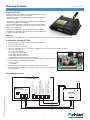
Inkopplingsschema Gateway Ec310 - Autodos
25
24
23
22
21
20
1918
14 15 16 17
13
Tx -
Tx +
Rx -
Rx +
GND
Tx term
Rx term
Rx term
COM
B
A
GND
PE
Al 4
COM
Al 3
Al 2
Al 1
D2-
D2+
D1-
D1+
COM
-V dc
+V dc
RS 485
WAN
LAN
RS 432
Tx
Rx
NO
Byglingar
Gateway EC310
Enheten är redan förkongurerad och medföljande beskrivning från
tillverkaren behöver normalt inte användas.
Inloggningsuppgifter samt ytterligare beskrivning av molntjänsten
redovisas separat.
I leveransen av Gateway EC310 art. 416231 ingår dokumentation,
registreringsuppgifter och nätadapter.
Notera att Gatewaymodulen inte behöver vara monterad alldeles
intill Autodos M. Den kan monteras i ett separat utrymme som har
tillgång till ethernet/WAN.
Observera att produkten är inte IP-klassad. Skall den monteras i
ett maskinrum med utsatt miljö bör den sitta i ett skåp som har den
IP-klass som miljön där kräver.
Säkerhet
Vid all elektrisk inkoppling eller annat arbete med Autodos och/eller EC310 skall anslutningsspänningen brytas.
Installation Gateway EC310
1. Montera EC310 mot ett fast underlag i ett IP-klassat utrymme.
2. Bryt strömmen till Autodos M.
3. Anslut en femledad kabel (5 x min 0,25 mm2) mellan EC310 och Autodos enligt kopplingsschema:
Tx - / Rx - överkopplas
Tx + / Rx + överkopplas
Tx + kopplas till A hos EC310
Tx – kopplas till B hos EC310
GND kopplas till COM hos EC310
Låt byglingar för Modbus-adressering sitta kvar.
Standby ingång 18 resp. 21 kopplas mot reläutgång NO resp. COM hos EC310.
4. Anslut nätadapterns enkelledare till EC310:
(+) på [+]
(-) på [-]
5. Anslut fastighetens ethernet anslutning mot WAN/Ethernet hos EC310.
6. Anslut nätadaptern till 230VAC och driftsätt Autodos M. Displayen kommer
initialt att visa Modbus-information innan den återgår till nedräkning från 60 sekunder.
Kopplingsschema el
Modbus-kortet monterat på bottenkortet 5 x min 0,25 mm2
12 VDC
WAN / Ethernet
Modbus RTU
9600 band, Parity None
Flödesmätare / 16 VDC PNP ingång
PNP in nivåvakt (larm vid sluten ingång)
Flödesmätare / NPN in ödesvakt
PNP in STDBY
Strömutgång 2 (redox/klor) 4–20mA
Strömutgång 1 (ph) 4–20mA
Flödesmätare / - GND strömutgångar
Temperatursensor
- GND temeratursensor
Tvåtrådskommunikation med PC
Analog In DI / Puls In Relay Power

6
SVENSKA
Gateway Autodos
MA60-26 SE (Instruktionens originalspråk)
E10075-0
150526 ASA
Autodos M1 / M2 / M3
GATEWAY
netbiter EC220
Inkopplingsschema Gateway EC220 - Autodos
25
24
23
22
21
20
1918
14 15 16 17
13
Modbus RTU
Tx -
Tx +
Rx -
Rx +
GND
Tx term
Rx term
Rx term
COM
B
A
Rs232
SIM
COM
NO
COM
Dl 2
Dl 1
COM
Al 1
Al 2
COM
OUT
GND
+Vdc
DI AI A0
RS 485
Byglingar
Gateway EC220
Enheten är redan förkongurerad och medföljande beskrivning från
tillverkaren behöver normalt inte användas.
Inloggningsuppgifter samt ytterligare beskrivning av molntjänsten
redovisas separat.
I leveransen av Gateway EC220 art. 416230 ingår dokumentation,
registreringsuppgifter och nätadapter.
Notera att Gatewaymodulen inte behöver vara monterad alldeles
intill Autodos M. Den kan monteras i ett separat utrymme som har
tillgång till mobil täckning.
Observera att produkten är inte IP-klassad. Skall den monteras i
ett maskinrum med utsatt miljö bör den sitta i ett skåp som har den
IP-klass som miljön där kräver.
Säkerhet
Vid all elektrisk inkoppling eller annat arbete med Autodos och/eller EC220 skall anslutningsspänningen brytas.
Installation Gateway EC220
1. Montera EC220 mot ett fast underlag i ett IP-klassat utrymme.
2. Anslut medföljande antenn.
3. Bryt strömmmen till Autodos M.
4. Anslut en femledad kabel (5 x min 0,25 mm2) mellan EC220 och Autodos enligt kopplingsschema:
Tx - / Rx - överkopplas
Tx + / Rx + överkopplas
Tx + kopplas till A hos EC220
Tx – kopplas till B hos EC220
GND kopplas till COM hos EC220
Låt byglingar för Modbus-adressering sitta kvar.
Standby ingång 18 resp. 21 kopplas mot reläutgång NO resp. COM hos EC220.
5. Anslut nätadapterns enkelledare till EC220:
(+ röd) på +VDC
(- vit) på GND
6. Anslut nätadaptern till 230VAC och driftsätt Autodos M. Displayen
kommer initialt att visa Modbus-information innan den återgår till nedräkning
från 60 sekunder.
Kopplingsschema el
12 VDC
5 x min 0,25 mm2
Modbus RTU
9600 band, Parity None
Flödesmätare / 16 VDC PNP ingång
PNP in nivåvakt (larm vid sluten ingång)
Flödesmätare / NPN in ödesvakt
PNP in STDBY
Strömutgång 2 (redox/klor) 4–20mA
Strömutgång 1 (pH) 4–20mA
Flödesmätare / - GND strömutgångar
Temperatursensor
- GND temeratursensor
Tvåtrådskommunikation med PC
Relay D1 A1 A0

7
SVENSKA
Gateway Autodos
MA60-26 SE (Instruktionens originalspråk)
EC220 EC310
M1 M2 M3
pH PB200 CLE3 CTE1 redox
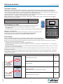
Fyll i uppgifterna nedan (vänligen TEXTA TYDLIGT) och skicka in dokumentet till [email protected]
Efter mottagen registrering återkommer Pahlén AB till er med era inloggningsuppgifter.
Återförsäljare
Kontaktperson (för- och efternamn)
Telefon
Email
Installationsdatum
Gateway-uppgifter
Gatewaymodell
SystemID (även IMEI/MAC-nr på Gateway)
Aktiveringskod (activation code)
Endast EC220: Telefonnr (phone mobile number)
Endast EC220: SIM-kort nr (SIM-card number)
Projektuppgifter
Projektnamn, max 30 tecken (företag, simanläggning, hotell, SPA etc.)
Systemnamn, max 30 tecken (t.ex. namn på poolen)
Autodosmodell
Serienr Autodos
Elektrodkonguration
Doseringsutrustning klor
Doseringsutrustning syra
Användaruppgifter - administratör (Serviceföretag eller liknande)
Kontaktperson (för- och efternamn)
Mobiltelefonnr.
Email
Larm via email och SMS
Användaruppgifter - gäst (valfritt) (Verksamhetsutövare eller liknande)
Kontaktperson (för- och efternamn)
Mobiltelefonnr.
Email
Larm via email och SMS
- Registreringsunderlag


9
ENGLISH
Gateway Autodos
MA60-26 GB Translation of the original instructions (Swedish)
Example:
SYSTEM ID
357973045706410
ACTIVATION CODE
CNEQPQA9
Example:
Phone number
+467190005071318
SIM-card number
89460954305000378343
Art.no.
Rev.no.
Scale
Designed by: Approved by:
Revised by: Date
Drawn by: Date
Drawing number
Assembly drawing no.
Surface treatment
part of ISO 2768-1
The tolerance class in accordance with this
E
Box 728, SE-194 27 Upplands Väsby, Sweden
Phone +46 8 59411050, Fax +46 8 59086880
TS 2010-07-08
Medium
Dimensions
Autodos M1-3
M11271 0
This document and its contents are the exclusive
property of Pahléns and may not be copied,
reproduced, transmitted or communicated to a third
party, or used for any purpose without written permission.
127 368,6
20
22,2594,4
5,2(4x)
639
46 46
160
80
A
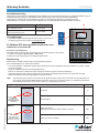
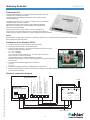
Product description
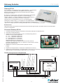
A Gateway EC220 or EC310 enables Internet communication between Autodos M and the Netbiter Argos cloud service for real-
time display and logging of water values and alarm handling via email (standard) or text messages (optional).
The EC220 uses a mobile data connection to the Internet, while the EC310 uses a xed Ethernet connection in a building.
With a Modbus RTU installed in the Autodos M, data communication is over a serial interface: RS485 via the Modbus protocol.
Product Pahlén item no.
Gateway EC310
includes AC adapter 230/12V Item no. 416231
Modbus-RTU
OPC communications module Item no. 416209
Requirements
• Your Autodos M must have system software version 5.6 or later.
If your unit has an earlier version, contact [email protected]
• A Modbus RTU communications module must be installed in your
Autodos M.
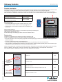
Check system software
Check the system software version in your Autodos M by pressing and holding the
[Alarm high] + [Alarm low] buttons.
The Autodos’s right-hand display (A) shows the current software version.
Registration
The product is shipped with documentation including registration data.
These are valuable documents and should be stored with appropriate care.
• Fill in this information in the accompanying registration document (last page). Include your installation, contact, project, and
system information.
• Send the completed document to [email protected]
If you need this document in electronic format, please contact us, preferably at the same E-mail address.
• Login information and additional documentation of the cloud service will be provided separately when we have received your
completed document. Gateway must be connected to WAN and be online.
NOTE: Each Gateway has a unique ID and will be connected in the system to the particular Autodos M that it has been paired
with. If the Gateway, at a later time, needs to communicate with a dierent Autodos, a new registration must be done.
If the Gateway module is swapped for another one, a new registration must be done.
Registration data EC310
Netbiter Argos
System ID YES
Activation code YES
SIM card
SIM card number
(The SIM card itself is already installed in the unit) NO
Telephone number for unit NO

10
ENGLISH
Gateway Autodos
MA60-26 GB Translation of the original instructions (Swedish)
Modbus-RTU
Item no. 416209 OPC communications module Modbus RTU
Safety
Before making any electrical connections or performing other work on the Autodos, the unit must be disconnected from
electrical power.
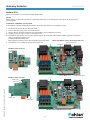
Installation of Modbus circuit board
(If the Modbus is already installed in your Autodos, proceed to the section for your Gateway model.)
1. Disconnect the Autodos M from electrical power.
2. Remove the upper (gray) cover from the Autodos M.
3. Remove the four screws that hold the cover (with display) on the Autodos M control box.
4. Carefully loosen the strip connector on the bottom card.
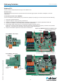
5. The Modbus card has one connector and 3 plastic clips on the underside. Place these in position opposite the specied
holes in the Autodos’s bottom card.
Carefully install the Modbus card.
Ensure that the connection is rm and the plastic clips lock in place.
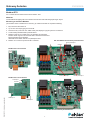
6. The Modbus is now installed on Autodos M’s bottom card Attach the Modbus card to the bottom card here
Modbus card installed on bottom card
Modbus card from below
Modbus card from above
Plastic clip 1
Plastic clip 2
Plastic clip 3
Connector
Connector
Hole for plastic clip 3 Hole for plastic clip 2
Hole for plastic clip 1

11
ENGLISH
Gateway Autodos
MA60-26 GB Translation of the original instructions (Swedish)
E10076-0
150527 ASA
Autodos M1 / M2 / M3
GATEWAY
netbiter EC310
Inkopplingsschema Gateway Ec310 - Autodos
25
24
23
22
21
20
1918
14 15 16 17
13
Tx -
Tx +
Rx -
Rx +
GND
Tx term
Rx term
Rx term
COM
B
A
GND
PE
Al 4
COM
Al 3
Al 2
Al 1
D2-
D2+
D1-
D1+
COM
-V dc
+V dc
RS 485
WAN
LAN
RS 432
Tx
Rx
NO
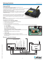
Strappings
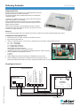
Gateway EC310
The unit is precongured, and the accompanying description from the
manufacturer is normally not needed.
Login information and additional description of the cloud service is
provided separately
The Gateway EC310, item no. 416231, is shipped with documentation,
registration data, and an AC adapter.
Note that the Gateway module need not be installed immediately
adjacent to the Autodos M. It can be installed in a separate area
with access to Ethernet/WAN.
Note that this product is not IP rated. If it is to be installed in an
engine room in an exposed environment, it should be placed inside a
cabinet whose IP rating corresponds to what is required in that environment.
Safety
Before making any electrical connections or performing other work on the Autodos and/or the EC310, the unit must be
disconnected from electrical power.
Installation of the Gateway EC310
1. Install the EC310 on a solid support in an IP-rated area.
2. Disconnect the Autodos M from electrical power.
3. Connect a 5-lead cable (5 x min 0,25 mm2) between the EC310 and the
Autodos per the connection diagram:
Tx – / Rx - (bridged)
Tx + / Rx + (bridged)
Tx + connects to A on the EC310 Tx – connects to B on the EC310
GND connects to COM on the EC310
Leave the strappings for Modbus addressing in position.
Standby inputs 18 and 21 connect to relay outputs NO and COM, respectively,
on the EC310.
4. Connect the AC adapter’s single-wire to the EC310:
(+) to [+]
(–) to [–]
5. Connect the building’s Ethernet to WAN/Ethernet on the EC310.
6. Connect the AC adapter to 230V AC and start the Autodos M. The display will initially show Modbus information, then revert
to a 60-second countdown.
Electrical connection diagram
5 x min 0,25 mm2
12 VDC
WAN / Ethernet
Modbus RTU
9600 band, Parity None
Flow meter / 16 VDC PNP input
PNP in level monitor (alarm when the input is closed)
Flow meter / NPN in ow monitor
PNP in STDBY
Power output 2 (redox/chlorine) 4–20mA
Power output 1 (pH) 4–20mA
Flow meter / - GND power outputs
Temperature sensor
- GND temerature sensor
Two-wire communication with PC
Analog In DI/Pulse In Relay Power

12
ENGLISH
Gateway Autodos
MA60-26 GB Translation of the original instructions (Swedish)
E10075-0
150526 ASA
Autodos M1 / M2 / M3
GATEWAY
netbiter EC220
Inkopplingsschema Gateway EC220 - Autodos
25
24
23
22
21
20
1918
14 15 16 17
13
Modbus RTU
Tx -
Tx +
Rx -
Rx +
GND
Tx term
Rx term
Rx term
COM
B
A
Rs232
SIM
COM
NO
COM
Dl 2
Dl 1
COM
Al 1
Al 2
COM
OUT
GND
+Vdc
DI AI A0
RS 485
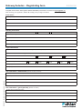
Strappings
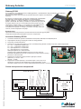
Gateway EC220
The unit is precongured, and the accompanying description from
the manufacturer is normally not needed.
Login information and additional description of the cloud service is provided separately.
The Gateway EC220, item no. 416230, is shipped with documentation,
registration data, and an AC adapter.
Note that the Gateway module need not be installed immediately adjacent
to the Autodos M. It can be installed in a separate area with access to
mobile data coverage.
Note that this product is not IP rated. If it is to be installed in an engine
room in an exposed environment, it should be placed inside a cabinet
whose IP rating corresponds to what is required in that environment.
Safety
Before making any electrical connections or performing other work on the Autodos and/or the EC220, the unit must be
disconnected from electrical power.
Installation of the Gateway EC220
1. Install the EC220 on a solid support in an IP-rated area.
2. Connect the supplied antenna.
3. Disconnect the Autodos M from electrical power.
4. Connect a 5-lead cable (5 x min 0,25 mm2) between the EC220 and the Autodos per the connection diagram:
Tx - / Rx - (bridged)
Tx + / Rx + (bridged)
Tx + connects to A on the EC220
Tx – connects to B on the EC220
GND connects to COM on the EC220
Leave the strappings for Modbus addressing in position.
Standby inputs 18 and 21 connect to relay outputs NO and COM, respectively,
on the EC220.
5. Connect the AC adapter’s single-wire to the EC220:
(+ red) to +VDC
(- white) to GND
6. Connect the AC adapter to 230V AC and start the Autodos M.
The display will initially show Modbus information, then revert to a countdown
from 60 seconds
Electrical connection diagram
12 VDC
5 x min 0,25 mm2
Modbus RTU
9600 band, Parity None
Flow meter / 16 VDC PNP input
PNP in level monitor
(alarm when the input is closed)
Flow meter / NPN in ow monitor
PNP in STDBY
Power output 2 (redox/chlorine) 4–20mA
Power output 1 (pH) 4–20mA
Flow meter / - GND power outputs
Temperature sensor
- GND temerature sensor
Two-wire communication with PC
Relay D1 A1 A0

13
ENGLISH
Gateway Autodos
MA60-26 GB Translation of the original instructions (Swedish)
EC220 EC310
M1 M2 M3
pH PB200 CLE3 CTE1 redox
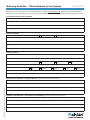
Complete the information below (please WRITE READABLE) and send the document to [email protected]
After receiving your registration, Pahlén AB will reply with your login information.
Retail dealer
Contact person (rst and last name)
Telephone
Email
Installation date
Gateway information
Gateway model
System ID (including IMEI/MAC number on the Gateway)
Activation code
EC220 only: Mobile telephone number)
EC220 only: SIM card number
Project declaration
Project name, max 30 characters (company, swimming complex, hotel, spa, etc.)
System namne, max 30 characters (e.g., name of pool)
Autodos model
Autodos serie number
Electrode conguration
Dosing equipment, chlorine
Dosing equipment, acid
User information - administrator (Service company or similar)
Contact person (rst and last name)
Mobile telephone number
Email
Alarm via email and text messages
User information - guest (optional) (Operator or similar)
Contact person (rst and last name)
Mobile telephone number
Email
Alarm via email and SMS
- Registrating form


15
РУССКИЙ
Gateway Autodos
MA60-26 RU Перевод оригинальных инструкций (Шведский)
Art.no.
Rev.no.
Scale
Designed by: Approved by:
Revised by: Date
Drawn by: Date
Drawing number
Assembly drawing no.
Surface treatment
part of ISO 2768-1
The tolerance class in accordance with this
E
Box 728, SE-194 27 Upplands Väsby, Sweden
Phone +46 8 59411050, Fax +46 8 59086880
TS 2010-07-08
Medium
Dimensions
Autodos M1-3
M11271 0
This document and its contents are the exclusive
property of Pahléns and may not be copied,
reproduced, transmitted or communicated to a third
party, or used for any purpose without written permission.
127 368,6
20
22,2594,4
5,2(4x)
639
46 46
160
80
A
www.pahlen.com
R
Black
Autodos M3
Редокс pH
528639
1 7
pH7 pH9
This document and its contents are the exclusive
property of Pahléns and may not be copied,
reproduced, transmitted or communicated to a third
party, or used for any purpose without written permission.
Overlay Autodos M3 (Rysk)
fritt klor , Redox, pH
178
LEXAN A350250 alt.Material =
Adhesive:
Polyesterfoil Fine texture Autotex F200
3M 8153 LE
Silver, PMS 877 C
White
Window
(transparent clear)
Blue , PMS 2945 C
111
R1 (4x)
Window
(transparent clear)
Art.no.
Rev.no.
Scale
Designed by: Approved by:
Revised by: Date
Drawn by: Date
Drawing number
Assembly drawing no.
Surface treatment
part of ISO 2768-1
The tolerance class in accordance with this
E
Box 728, SE-194 27 Upplands Väsby, Sweden
Phone +46 8 59411050, Fax +46 8 59086880
TSTS
Fine
2012-06-28
M11674
1:1
16013155
3
Активация
Настройки
0
15
13 14
11
10
12
Низкий
поток
Свободный хлор
АвтАвт
Дозация
Поток
л ч)(/
Темп
(ºC)
Поток
Темп
Дозирование щелочи
Дозирование кислоты
ВыклВыкл
Выбор
функции
Выбор
функции
Выбор
/Clщёл
Выбор
кислоты
pH
T.S 2012-08-29
K-алиб
ровка
Сброс
Аварийный режимАварийный режимАварийный режим
Kоды
доступа
Режим
ожидания
Kоды
доступа
Hижний
предел
/Cl/Re рН
В
C рН/
ерхний
предел
l/Re
Описание изделия
Gateway ЕС 220 и EC310 обеспечивают возможность связи через Интернет между Autodos М и облачным сервисом
Netbiter Argos с целью регистрации и отображения параметров воды в режиме реального времени. (Управления нет,
только перевод в спящий режим с отключением дозирования. Параметры менять нельзя.) Сообщения сигнализации могут
посылаться при помощи электронной почты (стандартно) или СМС (опционально).
Подключение к Интернету для ЕС220 осуществляется с использованием сети мобильной связи,, а подключение к сети
Ethernet для EC310 – с помощью соответствующей проводки в здании.
Модуль Modbus RTU, установленный в Autodos М, обеспечивает трафик данных через последовательный интерфейс:
RS485, согласно протоколу Modbus.
Изделие Артикул Pahlén
Gateway EC310 включая сетевой адаптер 230/12 В Артикул №: 416231
Modbus-RTU Коммуникационный модуль OPC Артикул №: 416209
Необходимые условия
• Ваш Autodos M должен иметь системное ПО версии 5.6 или более поздней.
При использовании более старой версии ПО обращайтесь по адресу
• В вашем Autodos M должен быть установлен коммуникационный модуль
Modbus-RTU
.
Проверьте системное ПО.
Проверьте, какая версия программного обеспечения установлена в Autodos М, нажав
и удерживая нажатыми кнопки сигнализации [Alarm high] + [Alarm low].
Теперь правый дисплей (A) Autodos показывает текущую версию ПО.
Регистрация
Вместе с изделием поставляется соответствующая документация и данные регистрации,
которые являются официальными документами и должны храниться надлежащим образом.
Внесите эти данные в прилагаемую регистрационную форму (последняя страница). Внесите свои данные установки,
контактные, проектные и системные данные.
• Отправьте заполненный документ по адресу [email protected].
Если этот документ нужен вам в электронном формате, пожалуйста, свяжитесь с нами (желательно – по этому адресу
электронной почты).
• Данные для входа в облачный сервис и его более подробное описание будет передано вам отдельно после того, как мы
получим от вас заполненный документ.
Примечание: Каждый шлюз Gateway имеет уникальный идентификатор (ID) и подключается к системе, как только к нему
подключается Autodos М.
В последнем случае, если шлюз Gateway должен обеспечивать обмен данными с другим модулем Autodos, необходимо
заново выполнить процедуру регистрации. Если модуль Gateway заменяется на другой, необходимо заново выполнить
процедуру регистрации.
Пример:
ИДЕНТИФИКАТОР
СИСТЕМЫ
357973045706410
КОД АКТИВАЦИИ
CNEQPQA9
Пример:
Номер телефона:
+467190005071318
Номер СИМ-карты:
89460954305000378343
Регистрационные данные EC310
Netbiter Argos
Идентификатор системы ДА
Код активации ДА
СИМ-карта
Номер СИМ-карты
(сама СИМ-карта уже установлена в модуль) НЕТ
Номер телефона для модуля НЕТ

16
РУССКИЙ
Gateway Autodos
MA60-26 RU Перевод оригинальных инструкций (Шведский)
Modbus-RTU
Артикул 416209 Коммуникационный модуль OPC Modbus- RTU
Безопасность
При выполнении электрического подключения или выполнении других работ на Autodos необходимо отключать
напряжение.
Установка печатной платы Modbus
(если плата Modbus в вашем Autodos уже установлена, перейдите к разделу для соответствующего шлюза Gateway).
1. Отключите питание Autodos M.
2. Поднимите верхнюю (серую) крышку на Autodos M.
3. Снимите четыре винта, которыми крышка (с дисплеем на ней) крепится к коробке управления Autodos M.
4. Осторожно отсоедините ленточный разъем на нижней стороне платы.
5. Плата Modbus имеет один разъем и 3 пластиковых зажима на нижней стороне.
Поместите их против соответствующих отверстий на нижней плате Autodos. Осторожно установите плату Modbus.
Убедитесь, что разъем полностью вошел и пластиковые зажимы защелкнулись.
6. Теперь плата Modbus закреплена на нижней плате Autodos M. Здесь плата Modbus крепится к нижней плате
Плата Modbus установлена на нижней плате
Плата Modbus, вид снизу
Плата Modbus, вид сверху
Пластиковый
зажим 1
Пластиковый
зажим 2 Пластиковый
зажим 3
Контакт
Отверстие для
пластикового зажима 3
Контакт:
Отверстие для пластикового
зажима 1.
Отверстие для
пластикового зажима 2

17
РУССКИЙ
Gateway Autodos
MA60-26 RU Перевод оригинальных инструкций (Шведский)
E10076-0
150527 ASA
Autodos M1 / M2 / M3
GATEWAY
netbiter EC310
Inkopplingsschema Gateway Ec310 - Autodos
25
24
23
22
21
20
1918
14 15 16 17
13
Tx -
Tx +
Rx -
Rx +
GND
Tx term
Rx term
Rx term
COM
B
A
GND
PE
Al 4
COM
Al 3
Al 2
Al 1
D2-
D2+
D1-
D1+
COM
-V dc
+V dc
RS 485
WAN
LAN
RS 432
Tx
Rx
NO
Плата Modbus установлена на нижней плате
Gateway EC310
Это устройство уже предварительно конфигурировано, и прилагаемое к
нему описание от изготовителя, как правило, не используется.
Данные для входа и дополнительное описание облачного сервиса
поставляются отдельно.
В комплект поставки EC310 с артикулом 416231 входит необходимая
документация, регистрационные данные и сетевой адаптер.
Следует отметить, что модуль Gateway не должен устанавливаться
рядом с Autodos М. Его можно установить в отдельном
пространстве, в котором имеется доступ к сети Ethernet/WAN.
Пожалуйста, имейте в виду, что это изделие не классифицировано
по IP. Если его нужно установить в машинном отделении с незащищенной
средой, его следует установить в шкафу, имеющем класс IP, соответствующий этой среде.
Безопасность
При выполнении электрического подключения или выполнении других работ на Autodos и/или ЕС310 необходимо
отключать напряжение.
Установка Gateway EC310
1. Установите EC310 на прочном основании в помещении, имеющем классификацию IP.
2. Отключите питание Autodos M.
3. Подключите пятижильный кабель (5 x мин. 0,25 мм2) между EC310 и
Autodos согласно схеме соединений:
Tx – / Rx –: соединение перемычкой
Tx + / Rx +: соединение перемычкой
Tx + присоединяется к т. A на EC310
Tx – присоединяется к т. В на EC310
GND присоединяется к COM на EC310
Перемычки для адресации Modbus должны остаться на месте.
В режиме ожидания вход 18 или 21 подключен соответственно к выходу
реле NO и COM на EC310
4. Подключите отдельный провод сетевого адаптера к EC310:
(+) к [+]
(–) к [–]
5. Подключите вывод Ethernet в помещении к WAN/Ethernet на EC310.
6. Подключите сетевой адаптер к сети 230 В перем. тока и запустите Autodos М. Сначала на дисплей выводятся
данные Modbus, затем начинается обратный отсчет от 60 секунд.
Схема электрических соединений
Клеммы
5 x мин. 0,25 мм2
12 В пост. тока
WAN / Ethernet
Modbus RTU
Полоса 9600, контроль
четности отсутствует
Датчик температуры
Датчик температуры - GND
Двухпроводная связь с PC
Аналоговый
вход
DI / Импу-
льсный вход
Реле Питание
Измеритель расхода / - GND, токовые выходы
Выходной ток 1 (pH) 4–20 мА
Выходной ток 2 (редокс/хлор) 4–20 мА
Вход PNP, режим STDBY
Измеритель расхода / вход NPN, реле расхода
PNP, реле уровня
(при закрытом входе подается сигнал тревоги)
Измеритель расхода / 16 В пост. тока, вход PNP Вход
Перемычки

18
РУССКИЙ
Gateway Autodos
MA60-26 RU Перевод оригинальных инструкций (Шведский)
E10075-0
150526 ASA
Autodos M1 / M2 / M3
GATEWAY
netbiter EC220
Inkopplingsschema Gateway EC220 - Autodos
25
24
23
22
21
20
1918
14 15 16 17
13
Modbus RTU
Tx -
Tx +
Rx -
Rx +
GND
Tx term
Rx term
Rx term
COM
B
A
Rs232
SIM
COM
NO
COM
Dl 2
Dl 1
COM
Al 1
Al 2
COM
OUT
GND
+Vdc
DI AI A0
RS 485
Gateway EC220
Это устройство уже предварительно конфигурировано, и прилагаемое к нему описание от изготовителя,
как правило, не используется.
Данные для входа и дополнительное описание облачного сервиса поставляются
отдельно.
В комплект поставки EC220 с артикулом 416230 входит необходимая
документация, регистрационные данные и сетевой адаптер.
Следует отметить, что модуль Gateway не должен устанавливаться
рядом с Autodos М. Его можно установить в отдельном пространстве,
в котором имеется доступ к сети мобильной связи (покрытие сети)
Пожалуйста, имейте в виду, что это изделие не классифицировано
по IP. Если его нужно установить в машинном отделении с
незащищенной средой, его следует установить в шкафу, имеющем
класс IP, соответствующий этой среде.
Безопасность
При выполнении электрического подключения или выполнении других работ
на Autodos и/или ЕС220 необходимо отключать напряжение.
Установка Gateway EC220
1. Установите EC220 на прочном основании в помещении, имеющем классификацию IP.
2. Подсоедините антенну, входящую в комплект оборудования.
3. Отключите питание Autodos M.
4. Подключите пятижильный кабель (5 x мин. 0,25 мм2) между EC220 и Autodos согласно схеме соединений:
Tx – / Rx –: соединение перемычкой
Tx + / Rx +: соединение перемычкой
Tx + присоединяется к т. A на EC220
Tx – присоединяется к т. В на EC220
GND присоединяется к C0M на EC220
Перемычки для адресации Modbus должны остаться на месте.
В режиме ожидания вход 18 или 21 подключен соответственно к выходу
реле NO и COM на EC220
5. Подключите отдельный провод сетевого адаптера к EC220:
(красный +) к +V пост. тока
(белый – ) к GND
6. Подключите сетевой адаптер к сети 230 В перем. тока и запустите
Autodos М. Сначала на дисплей выводятся данные Modbus, затем
начинается обратный отсчет. Схема соединений Gateway EC220 - Autodos Перемычки от 60 секунд.
Схема электрических соединений
Перемычки
Relay D1 A1 A0
5 x мин. 0,25 мм2
12 В пост. тока
Modbus RTU
Полоса 9600, контроль
четности отсутствует
Датчик температуры
Датчик температуры - GND
Двухпроводная связь с PC
Измеритель расхода / - GND, токовые выходы
Выходной ток 1 (pH) 4–20 мА
Выходной ток 2 (редокс/хлор) 4–20 мА
Вход PNP, режим STDBY
Измеритель расхода / вход NPN, реле расхода
PNP, реле уровня
(при закрытом входе подается сигнал тревоги)
Измеритель расхода / 16 В пост. тока, вход PNP Вход

19
РУССКИЙ
Gateway Autodos
MA60-26 RU Перевод оригинальных инструкций (Шведский)
EC220 EC310
M1 M2 M3
pH PB200 CLE3 CTE1 redox
Введите указанные ниже данные и отошлите документ по адресу [email protected] (пожалуйста, пишите разборчиво,
желательно печатными буквами). После получения регистрации Pahlén AB в ответ отправит вам ваши данные для входа.
Установщик/Розничный продавец
Контактное лицо (ФИО)
Телефон
Электронная почта
Дата установки
Данные Gateway
Модель Gateway
Идентификатор системы SystemID (а также номер IMEI/MAC на Gateway)
Код активирования
Только для EC220: номер мобильного телефона
Только для EC220: номер СИМ-карты
Данные проекта
Название проекта, компания, бассейн, отель, СПА и т.д. (макс. 30 символов)
Наименование системы (например, название бассейна) (макс. 30 символов)
Модель Autodos
Серийный номер Autodos
Конфигурация электродов
Оборудование для дозирования хлора
Оборудование для дозирования кислоты
Данные пользователя – администратор (сервисная компания или аналогично)
Контактное лицо (ФИО)
Номер мобильного телефона
Электронная почта
Тревожное сообщение - по электронной почте и/ипи с помощью СМС
Данные пользователя – посетитель (по желанию) (компания-оператор или аналогично)
Контактное лицо (ФИО)
Номер мобильного телефона
Электронная почта
Сообщение сигнализации - по электронной почте и/ипи с помощью СМС
- Обоснование регистрации
-
 1
1
-
 2
2
-
 3
3
-
 4
4
-
 5
5
-
 6
6
-
 7
7
-
 8
8
-
 9
9
-
 10
10
-
 11
11
-
 12
12
-
 13
13
-
 14
14
-
 15
15
-
 16
16
-
 17
17
-
 18
18
-
 19
19


