Yamaha S12 Bruksanvisning
- Kategori
- Kompletterande musikutrustning
- Typ
- Bruksanvisning

GEO S12 Series
Geo S1210 & Geo S1230 Tangent Array Modules
Geo S12 Analog TD Controller
User Manual
GEO S12 Series User Manual V1.02
Date: 07/03/2008

Page 2/112 INTRODUCTION
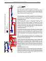
GEO Technology is radically new thinking
The GEO R&D Project has, to date, resulted in the following patent applications:
• The GEO Hyperboloid Reflective Wavesource™ differs radically from the megaphone-variant
type horns you know and love (or hate). “Tried and true” methods will produce entirely
unexpected results. HRW technology produces precise and predictable results.
• The Configurable Directivity Flange. A waveguide that allows the operator to alter its behaviour.
An unprecedented NEXO development that is easy to use – once you know how and when.
• The Directivity Phase Device needs no operator input to function, but it is reassuring to know that
the coupling of the midrange of the system is considered as important as the high frequencies…
• DSP-driven Directional Sub-bass devices are a new approach to controlling LF/VLF acoustic
energy.
GEO is not hard to use when you understand how…
The technology behind GEO is revolutionary, but it is grounded in years of practical experience with the
problems of delivering high quality professional sound to large audiences at high SPL levels. The GEO
toolbox includes GEOSoft -a simple yet powerful and highly predictive design tool. The array assembly
system is keyed to the design software and will easily enable you to deploy your design with great
precision. The NX242 Digital TDcontroller provides driver protection and system optimization as well as
DSP-driven cardioid pattern control for the CD18, GEO SUB and RS series Directional Subwoofers.
GEO is a high precision system
The GEO HRW™ controls acoustic energy more precisely than other multiple element waveguides. It
also makes GEO less forgiving of mistakes. Whilst conventional horns never combine into a coherent
array, they may deliver acceptable results even if the design and deployment of the system is less than
optimal. This is not the case with GEO where careless installation produces catastrophic results.
A GEO Tangent Array is not a “line array”
GEO Technology is equally effective in designing and deploying tangent horizontal arrays or curved
vertical arrays. For best results in a specific application the user needs to know how multi-speaker
arrays interact with audience geometry, along with the benefits and drawbacks of curved vertical arrays
and horizontal arrays.
Curved tangent arrays require different design techniques
For the past 20 years, sound reinforcement professionals have worked with horizontal arrays that use
conventional horns to deliver [more or less] ‘equal power to equal angles’. Curved vertical arrays are
designed to deliver [more or less] equal power to equal areas’. When arrays use conventional horns,
the lack of precision, overlap and interference masks errors in array design and aiming. The highly
precise GEO wavesource responds accurately, consistently and predictably to the design and
deployment of a curved vertical tangent array. This is why the GEO rigging system is designed to
control angular splay to 0.01° precision.
GEO curved tangent arrays require different operational techniques
Over the years, system designers and operators have developed a number of signal processing
techniques to disguise and partly overcome the limitations of horn design. “Frequency shading,”
“amplitude shading,” “system tuning,” all of these are tools of the advanced sound system operator.
NONE OF THESE TECHNIQUES ARE APPLICABLE TO GEO TANGENT ARRAYS. Instead of
enhancing the array’s performance they will severely degrade it.
Take time to learn how to get great results with GEO Technology. It is an investment that will pay off in
more satisfied clients, more efficient operating procedures and more recognition for your skill as a
sound system designer and operator. A comprehensive understanding of GEO theory, tangent arrays,
and specific features of the GEO S12 Series will help you to operate your system at its full potential.

INTRODUCTION Page 3/112
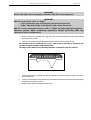
SAFETY ISSUES
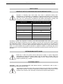
IMPORTANT NOTICE CONCERNING HIGH SOUND PRESSURE LEVELS
Exposure to extremely high noise levels may cause a permanent hearing loss.
Individuals vary considerably in susceptibility to noise-induced hearing loss, but nearly
everyone will lose some hearing if exposed to sufficiently intense noise for a sufficient
time. The U.S. Government’s Occupational and Health Administration (OSHA) has
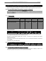
specified the following permissible noise level exposures: Sound Duration Per
Day In Hours Sound Level dBA, Slow Response
8 90
6 92
4 65
3 97
2 100
1 ½ 102
1 105
½ 110
¼ or less 115
According to OSHA, any exposure in excess of the above permissible limits could result in some
hearing loss. Ear plugs or protectors to the ear canals or over the ears must be worn when operating
this amplification system in order to prevent a permanent hearing loss, if exposure is in excess of the
limits as set forth above. To ensure against potentially dangerous exposure to high sound pressure
levels, it is recommended that all persons exposed to equipment capable of producing high sound
pressure levels such as this amplification system be protected by hearing protectors while this unit is in
operation.
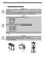
SYSTEM RIGGING SAFETY RULES
Before use of GEO S12, please ensure that anyone involved in system deployment
understands the rigging and stacking Safety rules are described in chapter “GEO S12
hardware setup procedure”, “SAFETY FIRST” pages 31 to 33 . Failure to do this exposes
people to potential injury or death.
ELECTRICAL SAFETY
WARNING ! GEO S12 TDCONTROLLER AND NX242 DIGITAL CONTROLLER ARE CLASS 1
APPARATUS AND MUST BE EATHED.
The green and yellow wire of the mains cord must always be connected to an installation
safety earth or ground. The earth is essential for personal safety as well as the correct
operation of the system, and is internally connected to all exposed metal surfaces.

Page 4/112 INTRODUCTION
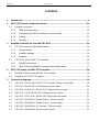
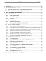
CONTENTS
1 Introduction.....................................................................................................................9
2 GEO S12 General Set-up Instructions.........................................................................12
2.1 Speaker connection.................................................................................................12
2.1.1 GEO S12 connectors........................................................................................12
2.1.2 Configuring Geo S12 for Passive or Active Mode.............................................12
2.1.3 Cabling .............................................................................................................12
2.1.4 Example:...........................................................................................................13
3 Amplifier Selection for use with GEO S12s................................................................14
3.1 GEO S12 recommended amplification.....................................................................14
3.1.1 Current rating....................................................................................................14
3.1.2 Amplifier settings ..............................................................................................14
3.1.3 Example............................................................................................................16
3.2 GEO S12s and NXAMP TDControllers....................................................................16
3.2.1 NXAMP connectors ..........................................................................................16
3.2.2 GEO S12s and NXAMP recommended configurations.....................................17
4 GEO S12 Setups on NEXO TD Controllers .................................................................18
4.1 Digital NX242-ES4 and NXAMP TDControllers.......................................................18
4.2 Analogue GEOS12 TDController.............................................................................19
5 Connection diagrams...................................................................................................19
5.1 GEO S12 & RS15 with GEOS12 TDController (Mono Omni Mode) ........................19
5.2 GEO S12 / NX242-ES4 (4 channels passive mode)................................................20
5.3 GEO S12 / ALPHA S2 / NX242-ES4 (Stereo passive mode) ..................................21
5.4 GEO S12 / CD18 / NX242-ES4 (Stereo passive mode) ..........................................22
5.5 GEO S12 / GEO SUB / NX242-ES4 (Stereo passive mode) ...................................23
5.6 GEO S12 / NXAMP4x1 (Bridge Stereo - Passive mode).........................................24
5.7 GEO S12 / NXAMP4x1 (Bridge Stereo - Active mode)............................................25
5.8 GEO S12 / NXAMP4x4 (4 Channels - Passive mode).............................................26
5.9 GEO S12 / NXAMP4x4 (Stereo Active mode).........................................................27

INTRODUCTION Page 5/112
6 GEOSoft2.......................................................................................................................28
7 Configurable Directivity Device...................................................................................29
7.1 Installing & removing GEO’s Configurable Directivity flanges .................................29
7.2 When & where to use Configurable Directivity flanges............................................30
8 GEO S12 hardware setup procedure ..........................................................................31
8.1 SAFETY FIRST.......................................................................................................31
8.1.1 Flown Systems Safety...................................................................................... 31
8.1.2 Ground Stacking Safety ...................................................................................32
8.1.3 Contacts ........................................................................................................... 33
8.2 General Description.................................................................................................34
8.2.1 Described configurations..................................................................................35
8.2.2 WARNINGS ON GEO S12 ACCESSORIES .................................................... 36
8.3 GEO S12 in fixed installations.................................................................................37
8.3.1 Fixed installation Accessories and kits .............................................................37
8.3.2 Single GEO S12 rigidly mounted on a wall or a ceiling (vertical or horizontal) . 38
8.3.3 Single GEO S12 cable mounted on a wall or a ceiling (vertical or horizontal).. 39
8.3.4 GEO S12 vertical array rigidly mounted on a ceiling ........................................ 40
8.3.5 GEO S12 vertical array cable mounted on a ceiling ......................................... 42
8.3.6 GEO S12 horizontal array rigidly mounted on a ceiling ....................................43
8.3.7 GEO S12 horizontal array cable mounted on a ceiling..................................... 45
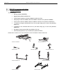
8.4 GEO S12 in touring applications .............................................................................46
8.4.1 Touring Accessories......................................................................................... 46
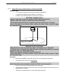
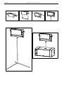
8.4.2 Single GEO S12 on speaker stand or on RS15 horizontally ............................47
8.4.3 Single GEO S12 flown vertically.......................................................................49
8.4.4 Single GEO S12 flown horizontally...................................................................50
8.4.5 Two GEO S12 on wind-up stand or on RS15 horizontally................................ 51
8.4.6 Two GEO S12 flown horizontally......................................................................55
8.4.7 Two or more GEO S12 flown vertically............................................................. 56
8.4.8 Three or more GEO S12 flown horizontally...................................................... 59
8.4.9 Ground stacked GEO S1210............................................................................63
8.5 Testing and Maintenance of the system..................................................................67

Page 6/112 INTRODUCTION
9 NEXO Analogue Geo S12TD Controller......................................................................68
9.1 Analogue TDcontroller Declaration of conformity.....................................................68
9.2 IMPORTANT SAFETY INSTRUCTIONS.................................................................68
9.3 Analogue TDcontroller Setting-Up Advice ...............................................................69
9.3.1 Mains Power.....................................................................................................69
9.3.2 Voltage setting..................................................................................................69
9.3.3 Mounting the TDcontroller in a rack (Grounding, shielding & safety issues).....69
9.3.4 Fuse .................................................................................................................69
9.3.5 Recommendations for wiring the sense lines ...................................................70
9.3.6 Recommendations for wiring the audio outputs................................................70
9.3.7 Electromagnetic environments .........................................................................70
9.3.8 Analogue signal cables.....................................................................................70
9.4 Analogue TDcontroller USER GUIDE......................................................................71
9.4.1 Read before use ...............................................................................................71
9.4.2 Front Panel .......................................................................................................72
9.4.3 Rear Panel........................................................................................................73
9.5 TDcontroller REFERENCE GUIDE..........................................................................74
9.5.1 Linear section ...................................................................................................74
9.5.2 Servo Control section ..................................................................................................74
10 NEXO NX242-ES4 Digital Controller for GEO S12..................................................76
10.1 NX242 Proprietary Functions...................................................................................76
10.1.1 Upgradable Firmware .......................................................................................76
10.1.2 EQ & Filtering ...................................................................................................76
10.1.3 Protection .........................................................................................................77

INTRODUCTION Page 7/112
10.2 Trouble shooting......................................................................................................78
10.2.1 Operation of Multiple TDcontrollers output channels........................................ 78
10.2.2 Amplifier Power (MENU 2.7) ............................................................................ 78
10.2.3 Amplifier Gain (MENU 2.6)............................................................................... 78
10.2.4 Gains................................................................................................................ 78
10.2.5 Delays ..............................................................................................................79
10.2.6 Reversed Cardioid Pattern ...............................................................................79
10.2.7 Using the wrong NX242 setups for a given cabinet..........................................79
10.2.8 Connections ..................................................................................................... 79
11 System alignment guidelines...................................................................................80
11.1 GEO S12 Vertical Cluster design ............................................................................80
11.2 Stacked RS15 / CD18 / S2 / GEO SUB and Flown GEO S12.................................80
11.3 Driving the GEO SUB’s from the AUX send............................................................81
11.4 Recommended installation tools and equipment.....................................................81
12 GEO S12 – RS15 / CD18/S2/GEOSUB System Check List.....................................83
12.1 Are the NX242 Digital TDcontrollers properly configured?......................................83
12.1.1 NX242 settings .................................................................................................83
12.2 Are the amplifiers properly configured?...................................................................83
12.3 Are the amps and the NX properly connected?.......................................................83
12.4 Are the speakers properly connected and angled ? ................................................84
12.5 Final Pre-Sound Check Check ................................................................................84
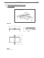
13 Technical Specifications..........................................................................................85
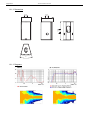
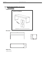
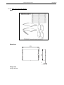
13.1 GEO S1230 Module ................................................................................................85
13.1.1 System specifications.......................................................................................85
13.1.2 Dimensions ......................................................................................................86
13.1.3 Diagrams..........................................................................................................86
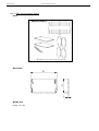
13.2 GEO S1210 Module ................................................................................................87
13.2.1 System specifications.......................................................................................87
13.2.2 Dimensions ......................................................................................................88
13.2.3 Diagrams..........................................................................................................88

Page 8/112 INTRODUCTION
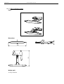
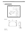
13.3 GEO S12 Touring Applications Accessories............................................................89
13.3.1 GEO S12 Bumper.............................................................................................89
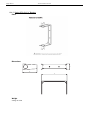
13.3.2 GEO S12 Rigging Plates ..................................................................................90
13.3.3 Tension Mode Link Bars for GEOS12-XBOW-V2.............................................91
13.3.4 Lifting Ring........................................................................................................92
13.3.5 Truss hook for GEOS12-SSBRK or GEOS12-PSBRK .....................................93
13.3.6 Truss hook for single vertical GEO S12............................................................94
13.3.7 “U” Bracket for single vertical GEO S12 ...........................................................95
13.3.8 U” Bracket for two vertical GEO S12 ................................................................96
13.3.9 Ground Stacking Device for up to 6 GEO S1210..............................................97
13.4 GEO S12 Fixed Installations Accessories ...............................................................98
13.4.1 GEO S12 Bumper.............................................................................................98
13.4.2 GEO S12 Connecting Plate 1 ...........................................................................99
13.4.3 GEO S12 Connecting Plate 2 .........................................................................100
13.4.4 GEO S12 Connecting Plate 3 .........................................................................101
13.4.5 Single GEO S12 “U” Bracket ..........................................................................102
13.4.6 “L” Bracket for cable suspension ....................................................................103
13.4.7 “U” Bracket for rigid suspension .....................................................................104
13.4.8 GEO S12 Push-Pins (BLGEOS).....................................................................105
13.5 GEO S12 Analogue TDcontrollers.........................................................................106
13.5.1 Specifications .................................................................................................106
13.5.2 Front and Rear Panel view .............................................................................106
13.6 NX242 TDcontroller with NX-Tension Card ...........................................................107
13.6.1 Specifications .................................................................................................107
13.6.2 Front and Rear Panel view .............................................................................107
13.6.3 Block Diagram ................................................................................................108
14 GEO S12 Series Parts & Accessories List ............................................................109
14.1 Modules & Control Electronics List........................................................................109
14.2 Accessories List.....................................................................................................109
15 USER NOTES...........................................................................................................111

INTRODUCTION Page 9/112
1 INTRODUCTION
Thank you for selecting a NEXO GEO S12 Series Tangent Array System. This manual is intended to
provide you with necessary and useful information about your GEO S12 System, which includes the
following products:
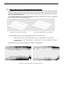
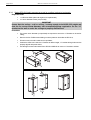
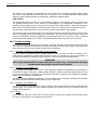
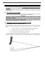
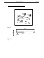
• GEO S1230 is a 30° Tangent Array Module.
It comprises 1x12” (30cm) Neodynium 16
ohms LF/MF driver and 1x3” voice coil, 1.4”
Throat 16 Ohm HF Driver loaded by a 28.5°
Hyperboloid Reflective Wavesource™.
• GEO S1210 is a 10° Tangent Array Module.
It comprises 1x12” (30cm) Neodynium 16
ohms LF/MF driver and 1x3” voice coil, 1.4”
Throat 16 Ohm HF Driver loaded by a 5°
Hyperboloid Reflective Wavesource™.
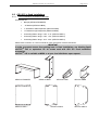
• GEO S12 Accessory Range. a full range of accessories that provides safe, flexible and simple
means of installing Geo S12 Tangent Arrays in fixed installation as well as in touring applications.

Page 10/112 INTRODUCTION
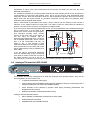
As for all NEXO systems, GEO S12s are controlled, powered and monitored by dedicated NEXO
TDControllers:
• GEO S12 TDController is based on PS analogue TDController design, and provides full control
for RS15 subwoofer in omnidirectional mode associated to Geo S12. It has 2 analogue inputs
(Left and Right) and 3 analogue outputs (RS15 Mono Omni, GeoS12 Left and GeoS12 Right);
• NX242-ES4 Digital TDController provides comprehensive control of GEO S12 loudspeakers in
multiple configurations. It allows Ethersound
TM
digital audio networking, as well as remote control
for all units in the network. It has 2 analogue / 4 digital inputs and 4 analogue / 4 digital outputs;
IMPORTANT
NX242 must be equipped with NX-Tension Card (ES4 or CAI) to access GEO S12 setups
• NXAMP4x1 and NXAMP 4x4 are Powered Digital Controllers, providing full control and
amplification for RS15 in multiple configurations. Both devices feature 4 analogue inputs and 4
speaker outputs. When equipped with optional card, 4 digital inputs in Ethersound
TM
digital audio
network format as well as remote control for all units in the network become available.
For a complete description of these controllers, please refer to User Manuals. The NX242 and NXAMP
DSP algorithms and parameters are fixed in software and updated regularly: Please consult the NEXO
web site (www.nexo.fr
) for the latest software releases.
GeoD Passive mode
Crossover 80Hz

INTRODUCTION Page 11/112
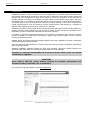
• GEOSoft2 Array Design Software assists in the design and implementation of vertical tangent
GEO arrays. Please consult the NEXO web site (www.NEXO.fr or www.NEXO-sa.com) for the
latest software releases.
Please devote your time and attention to reading this manual. A comprehensive understanding of GEO
theory, tangent arrays and specific features of GEO S12 will help you to operate your system at its full
potential.

Page 12/112 GEO S12 GENERAL SET-UP INSTRUCTIONS
2 GEO S12 GENERAL SET-UP INSTRUCTIONS
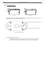
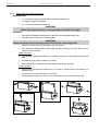
2.1 Speaker connection
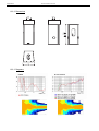
2.1.1 GEO S12 connectors
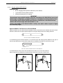
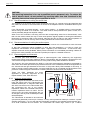
GEO S12 is connected with Speakon NL4FC plugs (not supplied). A wiring
diagram is printed on the connection panel located on the back of each
cabinet.The 4 pins of the 2 Speakon sockets identified in / out are connected in
parallel within the enclosure.
Either connector can be used to connect amplifier or to link to an additional Geo
S12 cabinet or to link to an optional Sub (if present). Therefore, a single 4-
conductor cable can connect two amplifier channels to various Geo S12 and/or
Sub Bass.
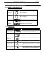
Connectors are wired as follows:
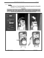
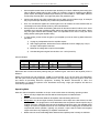
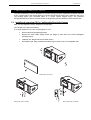
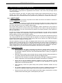
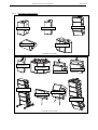
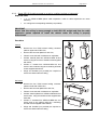
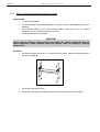
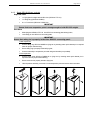
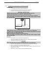
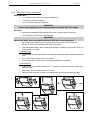
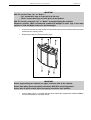
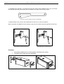
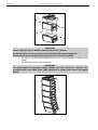
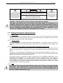
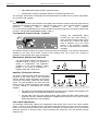
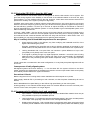
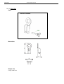
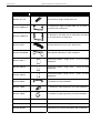
2.1.2 Configuring Geo S12 for Passive or Active Mode
• Remove the six TORX screws that hold the connector panel (figure next page);
• Remove the connector panel so that filter WAGO connectors become accessible;
• In Passive Mode, connector A (from filter) should be inserted in connector B (PCB “Passive In”),
and Connector D (“Passive Out”) should be connected to speakers via connector C.
• In Active Mode, WAGO Connector A (from filter) should be directly connected into to speakers via
connector C (PCB connectors B & D are then unused).
2.1.3 Cabling
NEXO recommends the exclusive use of multi-conductor cables to connect the system: the cable kit is
compatible with all the cabinets, and there is no possible confusion between LF, MF and HF sections.
Cable choice consists mainly of selecting cables of the correct sectional dimension (size) in relation to
the load resistance and the cable length. Too small a cable section will increase both its serial
resistance and its capacitance; this reduces the electrical power delivered to the loudspeaker and can
also induce response (damping factor) variations.
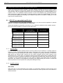
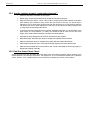
For a serial resistance less or equal to 4% of the load impedance (damping factor = 25), the maximum
cable length is given by:
L
max
= Z x S S in mm
2
, Z in Ohm, L
max
in meters
The table below indicates these values, for 3 common sizes.
Load Impedance (Ω)
2 3 4 6 8 12 16
Cable section Maximum Length (meters)
1,5 mm² (AWG #14) 3 4.5 6 9 12 18 24
2,5 mm² (AWG #12) 5 7.5 10 15 20 30 40
4 mm² (AWG #10) 8 12 16 24 32 48 64
Speakon
Connector
Passive
Mode
Active
Mode
1(-)
Ö
Not Connected Geo S12 LF (-)
1(+)
Ö
Not Connected Geo S12 LF (+)
2(-)
Ö
Geo S12 (-) Geo S12 HF (-)
2(+) Geo S12 (+) Geo S12 HF (+)

GEO S12 GENERAL SET-UP INSTRUCTIONS Page 13/112
2.1.4 Example:
• GEO S12 has a 16 Ohms nominal impedance in passive mode, so 4x Geo S12 wired in parallel
will present a 16/4 = 4 Ohm load impedance. The maximum acceptable 2x2.5 mm
2
(AWG #12)
cable length L
max
for such a cluster is 10 meters.
IMPORTANT
Long speaker cables induce capacitive effects – up to hundreds of pF depending on the
quality of the cable - with a high-pass effect on high frequencies. If long speaker cables
must be used, ensure that they do not remain coiled while in use.
CONNECTOR PANEL PASSIVE MODE ACTIVE MODE
B
A
D
C
B
D
A
C

Page 14/112 AMPLIFIER SELECTION FOR USE WITH GEO S12S
3 AMPLIFIER SELECTION FOR USE WITH GEO S12S
NEXO recommends high power amplifiers in all cases. Budget constraints are the only reason to select
lower power amplifiers. A lower power amplifier will not reduce the chances of driver damage due to
over-excursion, and may actually increase the risk of thermal damage due to sustained clipping. If an
incident occurs on an installation without protection, the fact that amplifiers only generating half their
rated output power (-3dB) are used will not change anything in respect of possible damage. This is due
to the fact that the RMS power handling of the weakest component in the system is always 6 to 10 dB
lower than the amplifier rating.
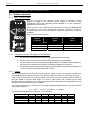
3.1 GEO S12 recommended amplification
GEO S12 is rated for very high power handling and has a 16 Ohms nominal impedance in passive
mode or 2 x 16 Ohms nominal impedance in active mode.
These high impedance values allow connection of 3 to 6 cabinets in parallel for each amplifier channel.
Nexo recommends amplifiers in agreement with table below:
Recommended
Amplifier#
Channel 1
LF in Active Mode or
LF+HF in Passive Mode
Channel 2
HF in Active Mode
GEO S12 Passive Mode
3 in parallel (5.3 Ohms load)
1750 to 3100 W / 4 Ohms
GEO S12 Active Mode
3 in parallel (5.3 Ohms load)
1750 to 3100 W / 4 Ohms 875to 1550 W / 4 Ohms
GEO S12 Passive Mode
4 in parallel (4 Ohms load)
2000 W to 3600 W / 4 Ohms -
GEO S12 Active Mode
4 in parallel (4 Ohms load)
2000 to 3600 W / 4 Ohms 1000 to 1800 W / 4 Ohms
GEO S12 Passive Mode
6 in parallel (2.7 Ohms load)
3300 to 6000 W / 2 Ohms
GEO S12 Active Mode
6 in parallel (2.7 Ohms load)
3300 to 6000 W / 2 Ohms 1650 to 3000 W / 2 Ohms
3.1.1 Current rating
It is very important that the amplifier behaves correctly under low load conditions. A speaker system is
reactive by nature: on transient signals like music it will require four to ten times more instantaneous
current than its nominal impedance would indicate. Amplifiers are generally specified by continuous
RMS power into resistive loads, however the only useful information about current capacity is the
specification into a 2 Ohm load. It is possible to perform an amplifier listening test by loading the amps
with twice the number of cabinets considered for the application (2 speakers per channel instead of one,
4 instead of 2) and running the amps up to the onset of clipping. If the signal does not noticeably
deteriorate, the amplifier is well adapted (overheating after approximately ten minutes is normal but
thermal protection must not operate too quickly after starting this test).
3.1.2 Amplifier settings
Gain value
Gain is the key to correct alignment of the system. It is especially important to know the gain of all
amplifiers used in your set-up. The tolerance should be about ±0.5 dB. In practice this can be difficult to
achieve because:

AMPLIFIER SELECTION FOR USE WITH GEO S12S Page 15/112
• Some amplifier brands have an identical input sensitivity for models of different power rating (this
infers a different voltage gain for each model). For example, a range of amplifiers with different
power outputs, all having a published input sensitivity of 775mV/0dBm or 1.55V/+6dBm, will have
a wide range of actual gains – the higher the power, the greater the gain.
• Various other brands may offer constant gain but only within a given product range, for example
they may fit fixed input sensitivity only on their semi-professional amps.
• Even if a manufacturer applies the constant gain rule to all models, the value selected will not
necessarily be the same as that chosen by other manufacturers.
• Some products can exhibit manufacturing tolerances for the same model of ±1dB or more. Some
amplifiers may have been modified, possibly without any label indicating the new values. Others
may have gain switches fitted internally where it is impossible for the user to verify the actual
setting without opening the amplifier casing.
• In cases where you don't know the gain of your amplifier (or want to check it) please follow this
procedure:
1) Unplug any loudspeakers from the amplifier outputs
2) With a signal generator, feed a sine wave at 1000Hz at a known voltage (say 0.5V) to
the input of the amplifier under test
3) Measure the voltage at the output of the amplifier
4) Calculate the gain using the formula Gain = 20 * LOG
10
(Vout/Vin).
Some examples:
Vin / Gain 20dB 26dB 32dB 37dB (1.4V sensitivity / 1350Wrms)
0.1 V 1 V 2 V 4 V 7.1 V
0.5 V 5 V 10 V 20 V 35.4 V
1 V 10 V 20 V 40 V 70.8 V
Remember that constant sensitivity settings will give a different gain value when the amplifier power is
different.
NEXO recommends low gain amplifiers: +26dB is recommended, as it is at the same time adequately
low and quite common amongst amplifier manufacturers. This gain setting improves signal to noise ratio
and allows all preceding electronic equipment, including the NX242 TDcontroller or GEO S12
TDController, to operate at optimum level. Remember that using a high gain amplifier will raise the
noise floor proportionally.
Operating Mode
Most two channel amplifiers available on the pro-audio market have the following operating modes:
• Stereo:
two fully independent channels deliver identical power into identical loads
• NEXO recommends Stereo Mode for all amplifier channels feeding GEO S12’s.
• Bridge-Mono:
the second signal channel processes the same input as the first channel, but with
reversed phase. The (single) load is connected between the two positive channel outputs using a
suitable connection. While the total output of the amplifier remains the same, the available output
voltage, the minimum impedance that can be connected and the voltage gain are doubled as
compared with stereo operation. Typically, only channel 1 input is active. Positive and negative
output connections vary depending on amplifier manufacturers.
• NEXO does not recommend Bridge Mono Mode unless amplifier power is clearly not sufficient.

Page 16/112 AMPLIFIER SELECTION FOR USE WITH GEO S12S
IMPORTANT
When in Bridge-Mono mode, check your amplifier user manual for proper connection of
outputs 1(+) and (2+) in relation to input phase.
• Parallel-mono: the output terminals of the two channels are configured in parallel using an
internal relay. The (single) load is connected either to the output of channel 1 or to that of channel
2 (as if in stereo). While the total output of the amplifier remains the same the output voltage level
is also the same as in stereo mode. The minimum impedance that can be connected is reduced
by half due to the fact that current capability is doubled. Typically, only channel 1 input is active.
• NEXO does not recommend Parallel-Mono Mode for any GEO S12 amplification.
Warning on amplifiers signal processing features
Some high-end amplifiers may include signal processing functions similar to those found in the NX242
TDcontroller or in GEO S12 TDController ("loudspeaker offset integration", "limiter", "compressor," etc.).
Moreover, when this processing is digital, computation latency time can introduce a few milliseconds
delay from input to output. These functions are not adapted to specific system requirements and may
interfere with the complex protection algorithms used in the NX242.
NEXO do not advise using other protection systems in conjunction with the NX242 and they should be
disabled.
IMPORTANT
For proper system protection, no latency time or non-linear devices should be
introduced between the output of the NX242 TDcontroller and the input of loudspeakers
through use of DSP modules such as internal amplifier signal processing.
3.1.3 Example
For a 6 GEO S12 cluster, and considering an amplifier model which is capable of delivering 2 x 3300W
into 2 Ohms or 2 x 2300W into 4 Ohms, NEXO recommends the following quantities and settings:
• Geo S12 Passive Mode:
• 1 stereo amplifier, 3 x GEO S12 per amplifier channel, mode switch in Stereo position, Gain
switch in 26 dB gain position, all dynamic or filter processing switches off.
3.2 GEO S12s and NXAMP TDControllers
NEXO Powered TDControllers NXAMP 4X1 & 4X4 are integrated solutions for Control and amplification
for all NEXO speaker ranges.
NXAMP4x1 and NXAMP4x4 power capability is listed in the table below:
Mode 4 Channels Bridge Stereo
NXAMP4x1 4 x 650 Watts / 8 Ohms
4 x 900 Watts / 4 Ohms
4 x 1300 Watts / 2 Ohms
2 x 1800 Watts / 8 Ohms
2 x 2600 Watts / 4 Ohms
NXAMP4x4 4 x 1900 Watts / 8 Ohms
4 x 3400 Watts / 4 Ohms
4 x 4000 Watts / 2 Ohms
2 x 6800 Watts / 8 Ohms
2 x 8000 Watts / 4 Ohms
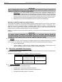
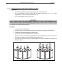
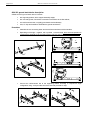
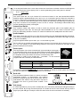
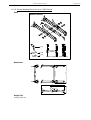
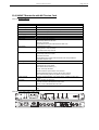
3.2.1 NXAMP connectors
NXAMP4x1 and NXAMP4x4 rear panels feature:
• 4 analog inputs / outputs (links) on XLR3 connectors;
• 4 digital inputs / outputs on RJ45 connectors with optional card;
• 4 speaker level outputs on NL4FC connectors.

AMPLIFIER SELECTION FOR USE WITH GEO S12S Page 17/112
Figure below shows connectors implementation on the rear panel.
3.2.2 GEO S12s and NXAMP recommended configurations
Passive Mode Active Mode
3 GEO S12 1 channel of NXAMP4x1 in Bridge Stereo Mode
1 channel of NXAMP4x4 in 4 channels mode
2 channels of NXAMP4x1 in Bridge Stereo Mode
2 channels of NXAMP4x4 in 4 channels mode
4 GEO S12 1 channel of NXAMP4x4 in 4 channels mode 2 channels of NXAMP4x4 in 4 channels mode

Page 18/112 GEO S12 SETUPS ON NEXO TD CONTROLLERS
4 GEO S12 SETUPS ON NEXO TD CONTROLLERS
4.1 Digital NX242-ES4 and NXAMP TDControllers
At GEO S12 User Manual current version printing time, 38 setups combining GEO S12s with NEXO
subwoofers are available in NX242 / NXAMP load 2.45. Please consult www.nexo-sa.com for upgrade
releases.
GEO S12 - 4 x S1210 Passive Wideband;
- 4 x S1230 Passive Wideband;
- 2 x S1210 Active Wideband;
- 2 x S1230 Active Wideband;
- 2 x S1210 Active X-Over 80 Hz;
- 2 x S1230 Active X-Over 80 Hz;
GEO S12
& ALPHA S2
- 2 x S1210 Passive Wideband + 2 x Alpha S2;
- 2 x S1230 Passive Wideband + 2 x Alpha S2;
- 2 x S1210 Passive X-Over 80 Hz + 2 x Alpha S2;
- 2 x S1230 Passive X-Over 80 Hz + 2 x Alpha S2;
GEO S12
& GEO SUB
- 2 x S1210 Passive Wideband + 1 x GeoSub 35 Hz – 80 Hz;
- 2 x S1230 Passive Wideband + 1 x GeoSub 35 Hz – 80 Hz;
- 2 x S1210 Passive Wideband + 1 x GeoSub 35 Hz – 200 Hz;
- 2 x S1230 Passive Wideband + 1 x GeoSub 35 Hz – 200 Hz;
- 2 x S1210 Passive X-Over 80 Hz + 1 x GeoSub 35 Hz – 80 Hz;
- 2 x S1230 Passive X-Over 80 Hz + 1 x GeoSub 35 Hz – 80 Hz;
- 2 x S1210 Passive X-Over 80 Hz + 1 x GeoSub 35 Hz – 200 Hz;
- 2 x S1230 Passive X-Over 80 Hz + 1 x GeoSub 35 Hz – 200 Hz;
- 2 x S1210 Active X-Over 80 Hz + 1 x GeoSub 35 Hz – 80 Hz;
- 2 x S1230 Active X-Over 80 Hz + 1 x GeoSub 35 Hz – 80 Hz;
- 2 x S1210 Active X-Over 80 Hz + 1 x GeoSub 35 Hz – 200 Hz;
- 2 x S1230 Active X-Over 80 Hz + 1 x GeoSub 35 Hz – 200 Hz;
GEO S12
& CD18
- 2 x S1210 Passive Wideband + 1 x CD18 85Hz;
- 2 x S1230 Passive Wideband + 1 x CD18 85 Hz;
- 2 x S1210 Passive X-Over + 1 x CD18 85 Hz;
- 2 x S1230 Passive X-Over + 1 x CD18 85 Hz;
- 2 x S1210 Active X-Over + 1 x CD18 85 Hz;
- 2 x S1230 Active X-Over + 1 x CD18 85 Hz;
GEO S12
& RS15
- 2 RS15 omni 35Hz-80Hz + 2 x S1210 Passive Wideband
- 2 RS15 omni 35Hz-80Hz + 2 x S1230 Passive Wideband
- 1 x RS15 cardio 35Hz-80Hz + 1 x S1210 Active Wideband
- 1 x RS15 cardio 35Hz-80Hz + 1 x S1230 Active Wideband
- 2 RS15 omni 35Hz-80Hz + 2 x S1210 Passive X-Over
- 2 RS15 omni 35Hz-80Hz + 2 x S1230 Passive X-Over
- 1 x RS15 cardio 35Hz-80Hz + 2 x S1210 Passive X-Over
- 1 x RS15 cardio 35Hz-80Hz + 2 x S1230 Passive X-Over
- 1 x RS15 cardio 35Hz-80Hz + 1 x S1210 Active X-Over
- 1 x RS15 cardio 35Hz-80Hz + 1 x S1230 Active X-Over

CONNECTION DIAGRAMS Page 19/112
4.2 Analogue GEOS12 TDController
GEO S12 TDController parameters have been optimized for 1 x RS15 (omni mode, mono) used in
conjunction with 2 x GEO S1210’s or 2 Geo x S1230’s (mono or stereo).
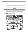
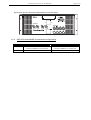
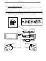
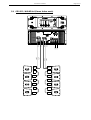
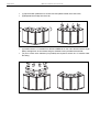
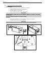
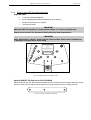
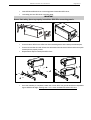
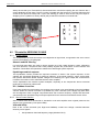
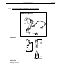
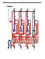
5 CONNECTION DIAGRAMS
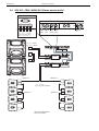
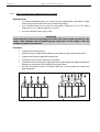
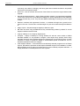
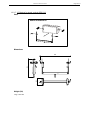
5.1 GEO S12 & RS15 with GEOS12 TDController (Mono Omni Mode)
AMPLIFIER 1
AMPLIFIER 2
MONO
STEREO
Speakon 4
1 (+) / 1 (-) VLF1 *
2 (+) / 2 (-) VLF2 *
Speakon 4
Speakon 4
Speakon 4
Speakon 4
1 (+) / 1 (-) N.C.
2 (+) / 2 (-) FULL RANGE
Speakon 4
1 (+) / 1 (-) VLF
2 (+) / 2 (-) N.C.
TO AMPLIFIERS
B
ALANC
E
D IN
P
UT
S
RIGHT
LEFT
-
6dB
-
12dB
0dB
OUT
P
UT
L
E
V
E
L
B
ALANC
E
D OUT
P
UT
S
RIGHT LEFTSUB L+R
E
A
R
TH
LI
F
T
FROM AMPLIFIERS
+ 3-
+ 2 - + 1 -
S
E
N
S
E
IN
P
UT
(from amp terminals)
CAUTION
!
Sense must be connected for
speaker protection
SEE USER MANUAL
STEREO
IN
GEOS12
LEFT
GEOS12
RIGHT
SUB
OUT
GEOS12
LEFT
GEOS12
RIGHT
SUB
* VLF1 and VLF2 on one amplifier channel

Page 20/112 CONNECTION DIAGRAMS
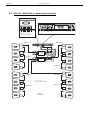
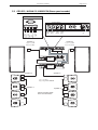
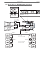
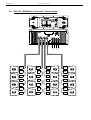
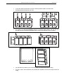
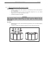
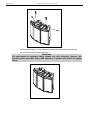
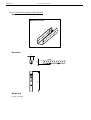
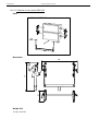
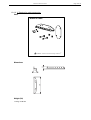
5.2 GEO S12 / NX242-ES4 (4 channels passive mode)
AMPLIFIER 1
AMPLIFIER 2
GEOS12
#3
IN
1
TO AMPLIFIERS
STEREO
FROM AMPLIFIERS
GEOS12
#3
GEOS12
#4
+ 4 - + 3-
STEREO
GEOS12
4 CHANNELS
+ 2 - + 1 -
Speakon 4
Speakon 4
Speakon 4
1 (+) / 1 (-) N.C.
2 (+) / 2 (-) FULL RANGE
GEOS12
#4
Speakon 4
Speakon 4
Speakon 4
Speakon 4
Speakon 4
GEOS12
#1
GEOS12
#2
IN
2
GEOS12
#1
GEOS12
#2
Sidan laddas ...
Sidan laddas ...
Sidan laddas ...
Sidan laddas ...
Sidan laddas ...
Sidan laddas ...
Sidan laddas ...
Sidan laddas ...
Sidan laddas ...
Sidan laddas ...
Sidan laddas ...
Sidan laddas ...
Sidan laddas ...
Sidan laddas ...
Sidan laddas ...
Sidan laddas ...
Sidan laddas ...
Sidan laddas ...
Sidan laddas ...
Sidan laddas ...
Sidan laddas ...
Sidan laddas ...
Sidan laddas ...
Sidan laddas ...
Sidan laddas ...
Sidan laddas ...
Sidan laddas ...
Sidan laddas ...
Sidan laddas ...
Sidan laddas ...
Sidan laddas ...
Sidan laddas ...
Sidan laddas ...
Sidan laddas ...
Sidan laddas ...
Sidan laddas ...
Sidan laddas ...
Sidan laddas ...
Sidan laddas ...
Sidan laddas ...
Sidan laddas ...
Sidan laddas ...
Sidan laddas ...
Sidan laddas ...
Sidan laddas ...
Sidan laddas ...
Sidan laddas ...
Sidan laddas ...
Sidan laddas ...
Sidan laddas ...
Sidan laddas ...
Sidan laddas ...
Sidan laddas ...
Sidan laddas ...
Sidan laddas ...
Sidan laddas ...
Sidan laddas ...
Sidan laddas ...
Sidan laddas ...
Sidan laddas ...
Sidan laddas ...
Sidan laddas ...
Sidan laddas ...
Sidan laddas ...
Sidan laddas ...
Sidan laddas ...
Sidan laddas ...
Sidan laddas ...
Sidan laddas ...
Sidan laddas ...
Sidan laddas ...
Sidan laddas ...
Sidan laddas ...
Sidan laddas ...
Sidan laddas ...
Sidan laddas ...
Sidan laddas ...
Sidan laddas ...
Sidan laddas ...
Sidan laddas ...
Sidan laddas ...
Sidan laddas ...
Sidan laddas ...
Sidan laddas ...
Sidan laddas ...
Sidan laddas ...
Sidan laddas ...
Sidan laddas ...
Sidan laddas ...
Sidan laddas ...
Sidan laddas ...
Sidan laddas ...
-
 1
1
-
 2
2
-
 3
3
-
 4
4
-
 5
5
-
 6
6
-
 7
7
-
 8
8
-
 9
9
-
 10
10
-
 11
11
-
 12
12
-
 13
13
-
 14
14
-
 15
15
-
 16
16
-
 17
17
-
 18
18
-
 19
19
-
 20
20
-
 21
21
-
 22
22
-
 23
23
-
 24
24
-
 25
25
-
 26
26
-
 27
27
-
 28
28
-
 29
29
-
 30
30
-
 31
31
-
 32
32
-
 33
33
-
 34
34
-
 35
35
-
 36
36
-
 37
37
-
 38
38
-
 39
39
-
 40
40
-
 41
41
-
 42
42
-
 43
43
-
 44
44
-
 45
45
-
 46
46
-
 47
47
-
 48
48
-
 49
49
-
 50
50
-
 51
51
-
 52
52
-
 53
53
-
 54
54
-
 55
55
-
 56
56
-
 57
57
-
 58
58
-
 59
59
-
 60
60
-
 61
61
-
 62
62
-
 63
63
-
 64
64
-
 65
65
-
 66
66
-
 67
67
-
 68
68
-
 69
69
-
 70
70
-
 71
71
-
 72
72
-
 73
73
-
 74
74
-
 75
75
-
 76
76
-
 77
77
-
 78
78
-
 79
79
-
 80
80
-
 81
81
-
 82
82
-
 83
83
-
 84
84
-
 85
85
-
 86
86
-
 87
87
-
 88
88
-
 89
89
-
 90
90
-
 91
91
-
 92
92
-
 93
93
-
 94
94
-
 95
95
-
 96
96
-
 97
97
-
 98
98
-
 99
99
-
 100
100
-
 101
101
-
 102
102
-
 103
103
-
 104
104
-
 105
105
-
 106
106
-
 107
107
-
 108
108
-
 109
109
-
 110
110
-
 111
111
-
 112
112


Yamaha S12 Bruksanvisning
- Kategori
- Kompletterande musikutrustning
- Typ
- Bruksanvisning
på andra språk
- italiano: Yamaha S12 Manuale del proprietario
- čeština: Yamaha S12 Návod k obsluze
- español: Yamaha S12 El manual del propietario
- Deutsch: Yamaha S12 Bedienungsanleitung
- polski: Yamaha S12 Instrukcja obsługi
- português: Yamaha S12 Manual do proprietário
- français: Yamaha S12 Le manuel du propriétaire
- 日本語: Yamaha S12 取扱説明書
- Türkçe: Yamaha S12 El kitabı
- English: Yamaha S12 Owner's manual
- dansk: Yamaha S12 Brugervejledning
- Nederlands: Yamaha S12 de handleiding
- română: Yamaha S12 Manualul proprietarului
Relaterade papper
Andra dokument
-
Q Acoustics 2000i serues Användarmanual
-
Bose F1 Powered Subwoofer Bruksanvisning
-
Hach SC200 Basic User Manual
-
Genelec 5051A Active Subwoofer Bruksanvisningar
-
-
-
Ingersoll-Rand L5H600 Bruksanvisningar
-
Bose L1 Model II Bruksanvisning
-
-
 Pressalit RK1181 Användarguide
