
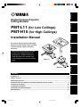
Digital Cinema Projector
Ceiling Bracket
PMT-L11 (for Low Ceilings)
PMT-H15 (for High Ceilings)
Installation Manual
Be sure to read this manual thoroughly
before using this bracket. After you have
read this manual, retain it for future
reference.
When installing the projector using this
bracket, all installation work must be
performed by a qualified contractor or
dealer personnel. The customer must
never attempt to perform this installation
work.
Packing List .................................................................................................................................. 4
Names of Parts ............................................................................................................................. 5
Dimensions of Parts .................................................................................................................... 7
Guidelines for the Projector Installation Position and Screen Size ........................................ 8
Installation Examples ................................................................................................................ 10
Installing the Projector .............................................................................................................. 11
Adjusting the Projection Angle................................................................................................. 14
Specifications ............................................................................................................................. 16
Contents
(PMT-L11)
(PMT-H15)
English
Français
Deutsch
Svenska
Italiano
Español
Nederlands
11PMT_TOC_E 5/29/1, 9:16 AM1

E-2
Safety Instruction
1. Always follow the instructions set forth in this manual when installing the projector
using this bracket.
Improper or inadequate installation could cause the projector to fall and injure someone.
2. The installation must be secure enough to bear the weight of the projector, the ceiling
bracket, and other hardware indefinitely, and must also be secure enough to withstand
vibration.
Inadequate installation could cause the projector to fall and injure someone.
3. To ensure safety, all bolts and screws must be tightened securely.
Loose bolts or screws could cause the projector to fall and injure someone.
4. Use only the parts provided with the bracket, and any other parts (commrecially
available) that are specified in this manual.
Using other parts could cause the projector to fall and injure someone.
5. Do not modify the bracket or the parts provided with the bracket.
Modifying the bracket or the other parts could cause the projector to fall and injure someone.
6. Do not use damaged parts.
Using damaged parts could cause the projector to fall and injure someone.
If any parts become damaged, contact your dealer.
7. Make sure to leave enough open space around the unit to allow heat generated by the
projector to dissipate.
Failure to provide adequate space around the unit could cause the projector to overheat internally, causing a
fire.
8. Before replacing the lamp cartridge, always remove the projector (with the mounting
adapter attached) from the ceiling bracket.
Attempting to replace the lamp cartridge while the projector is attached to the ceiling bracket could cause
the projector or the ceiling bracket to fall and injure someone.
11PMT_TOC_E 5/29/1, 9:16 AM2

E-3
English
Français
Deutsch
Svenska
Italiano
Español
Nederlands
9. Never hang from the projector or the ceiling bracket.
Hanging from the projector or the ceiling bracket could cause the projector or the ceiling bracket to fall and
injure someone.
10. Do not install the projector in a location near an air conditioning vent or in a location
subject to vibration.
Such conditions could have an adverse effect on the projector, and could even cause a fire or electric shock.
11. Do not install the projector in a location that is subject to high levels of dust or
humidity.
Dust accumulating inside the projector could cause a short circuit that in turn could cause a fire or electric
shock.
12. Do not install the projector in a location that is exposed to direct sunlight or in a
location that is subject to extreme fluctuations in temperature (such as near an air
conditioner).
Such conditions can cause the projector housing to warp or to become discolored.
13. Do not wipe the exterior of the ceiling bracket with benzene, paint thinner or cleaning
compounds.
Doing so could damage the finish.
14. Special techniques and experience are essential when installing the projector using
this bracket. Request that your dealer arrange to have the equipment installed. The
customer should never attempt to suspend the projector from the ceiling.
Improper installation could cause the ceiling bracket or the projector to fall and injure someone.
15. Once the projector is installed, safety checks should be conducted on a regular basis.
If the projector is used over an extended period of time, screws can become loose and the installation can
become weaker due to the passage of time, vibration, etc.
11PMT_TOC_E 5/29/1, 9:16 AM3

E-4
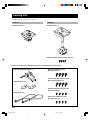
Packing List
Confirm that all of the parts are present.
PMT-L11
Ceiling bracket x 1
PMT-H15
Ceiling bracket x 1
Common Components (The following parts are provided with each bracket.)
Projector mounting adapter x 1
Projector mounting screws
(M6, pan head) x 4
Adjustment pole locking screws (M5) x 4
Safety brackets x 2
Safety wires x 2
Vertical angle adjustment screws
(M6, hexagonal head) x 4
Safety bracket mounting screws
(M4, pan head) x 4
Safety wire mounting screws
(M4, pan head) x 4
12PMT_BODY_E 5/29/1, 9:16 AM4

E-5
English
Français
Deutsch
Svenska
Italiano
Español
Nederlands
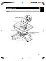
Names of Parts
PMT-L11
Ceiling bracket
Projector mounting adapter
Tilt angle adjustment screws
(There are also screws on the
opposite side.)
Vertical angle adjustment screws
(There are also screws on the
opposite side.)
Horizontal angle adjustment
screws
Mounting guide pin
12PMT_BODY_E 5/29/1, 9:16 AM5

E-6
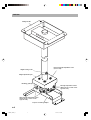
PMT-H15
Height locking screw
Ceiling bracket
Projector mounting adapter
Tilt angle adjustment screws
(There are also screws on the
opposite side.)
Vertical angle adjustment screws
(There are also screws on the
opposite side.)
Horizontal angle adjustment screw
(four in total)
Height adjustment pole
Mounting guide pin
12PMT_BODY_E 5/29/1, 9:16 AM6

E-7
English
Français
Deutsch
Svenska
Italiano
Español
Nederlands
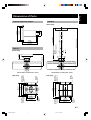
230 mm
Dimensions of Parts
Projector Mounting Adapter
with the DPX-1 installed (lens center)
[Top View]
PMT-H15
[Front View]
with the DPX-1 installed (lens center)
[Top View]
PMT-L11
[Front View]
200 mm
190 mm
212 mm
55 mm
80 mm
81 mm
201.65 mm
10˚
10˚
Ø10 x 13 mm
Ø3/8 x 1/2 inch
(elliptical hole)
Ø10 mm
Ø3/8 inch
(hole)
Ø9 mm
Ø3/8 inch
(hole)
Ø9 x 13 mm
Ø3/8 x 1/2 inch
(elliptical hole)
10˚
10˚
196 mm
170 mm
140 mm
120 mm
156 mm
777 to 1347 mm
896.65 to 1466.65 mm
226 mm
200 mm
140 mm
175 mm
Ø8.8 mm
Ø3/16 inch
(fully penetrating holes)
9-9/16 inch
7-7/8 inch
7-1/2 inch
8-3/8 inch
3-1/8 inch
2-3/16 inch
7-3/4 inch
6-11/16 inch
5-1/2 inch
3-3/16 inch
7-15/16 inch
4-3/4 inch
6-1/8 inch
30-9/16 to 53 inch
35-5/16 to 57-3/4 inch
1-3/16 inch
Ø10 x 13 mm
Ø3/8 x 1/2 inch
(elliptical hole)
Ø10 mm
Ø3/8 inch
(hole)
Ø9 mm
Ø3/8 inch
(hole)
Ø9 x 13 mm
Ø3/8 x 1/2 inch
(elliptical hole)
8-7/8 inch
7-7/8 inch
30 mm
5-1/2 inch
6-7/8 inch
12PMT_BODY_E 5/29/1, 9:16 AM7

E-8
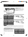
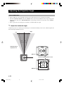
Guidelines for the Projector Installation Position and
Screen Size
• The relationship between the projection distance and the screen size is shown below. Use these values as
guidelines for determining the installation position.
When using a 4:3 Screen
Screen size Projection distance (Wide/Tele.)
(inch) (m) (feet, inch)
60 2.4 – 2.9 7’ 10” – 9’ 6”
80 3.2 – 3.9 10’ 6” – 12’ 10”
100 4.0 – 4.9 13’ 1” – 16’
120 4.8 – 5.8 15’ 9” – 19’
150 6.1 – 7.3 20’ – 23’ 11”
200 8.1 – 9.8 26’ 7” – 32’ 2”
When using a 16:9 Screen
Screen size Projection distance (Wide/Tele.)
(inch) (m) (feet, inch)
60 2.6 – 3.2 8’ 6” – 10’ 6”
80 3.5 – 4.2 11’ 6” – 13’ 9”
100 4.4 – 5.3 14’ 5” – 17’ 5”
120 5.3 – 6.4 17’ 5” – 21’
150 6.6 – 8.0 21’ 8” – 26’ 3”
200 8.8 – 10.6 28’ 10” – 34’ 9”
Cautions
• The projection distance is the horizontal distance from the surface of the projector lens to the surface of the screen.
In the case of the DPX-1, the surface of the lens is recessed by approximately 4 cm (1-9/16 inch) from its exterior.
• Although the ceiling bracket permits adjustment of the vertical angle of the projector over a range of ±15˚, a large
angle adjustment will distort the projected image somewhat. Therefore, we recommend adjusting both the angle of
the projector and the angle of the screen.
Adjustment Through Digital Lens Shift
Screen size Distance to top edge of screen
(inch) (cm) (inch)
60 19 – 44 7-1/2 to 17-5/16
80 26 – 59 10-1/4 to 23-1/4
100 32 – 74 12-5/8 to 29-1/8
120 39 – 89 15-3/8 to 35
150 49 – 111 19-3/8 to 43-3/4
200 65 – 145 25-5/8 to 57
Distance from center of projector’s lens to top
edge of screen
(See the owner’s manual for the projector.)
Screen
Projection distance
(See the diagram below.)
Distance from ceiling installation surface to
center of lens
PMT-L11: 20 cm (7-7/8 inch)
PMT-H15: 90 to 147 cm (35-7/16 to 57-7/8 inch)
(can be adjusted in 3 cm (1-3/16 inch) steps)
Ceiling
When “SCREEN ASPECT” is set to 16:9 in the
SETUP menu, it is possible to use the projector’s
digital shift function to adjust the distance from the
center of the projector’s lens to the top edge of the
screen. The range of adjustment is indicated at right.
Distance from the center of the
ceiling bracket to the front edge
of the projector:
approximately 20 cm (7-7/8 inch)
Smaller ← Screen size → Larger
Projection distance Zoom function
Wide
Tele.
Wide
Tele.
Wide
Tele.
Projection distance
Zoom function
Wide
Tele.
Wide
Tele.
Wide
Tele.
Smaller ← Screen size → Larger
12PMT_BODY_E 5/29/1, 9:16 AM8

E-9
English
Français
Deutsch
Svenska
Italiano
Español
Nederlands
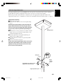
PMT-H15 Height Adjustment
The height adjustment pole for the PMT-H15 has holes spaced 3 cm apart that can be used to adjust the
height. When the bracket is shipped from the factory, the pole is set at the shortest height.
Follow the procedure described below to adjust the pole to the appropriate height. For details on the
appropriate height, refer to “Guidelines for the Projector Installation Position and Screen Size” on page 8.
[Adjustment Procedure]
1 Remove the safety pin.
2 Loosen the nut, and then remove the height locking
screw.
Removing the height locking screw will unlock the
height adjustment pole from the ceiling bracket. In
order to ensure that the height adjustment pole does
not fall, always hold the pole while performing this
work.
3
Determine the correct position in accordance with the
height of the screen, insert the height locking screw,
and then hand-tighten the nut.
4 Securely tighten the four height adjustment pole
locking screws (M5) provided.
5 Securely tighten the nut that was previously hand-
tightened.
6 Be sure to insert the safety pin.
Finally, after adjusting the height, make sure that the
adjustment pole locking screws and the nut are all
tightened securely. Also make sure that the safety
pin has been inserted properly.
Safety pin
Nut
Adjustment pole locking screws
(Tighten the other side also.)
Height
locking
screw
1
2
3
4
Hight adjustment pole
Ceiling bracket
12PMT_BODY_E 5/29/1, 9:16 AM9

E-10
Installation Examples
When the ceiling is made of wood
1 Drill matching holes through the reinforcing
plate and the ceiling in the proper locations
and then pass bolts through the holes.
2 Tighten the bolts to secure the reinforcing
plate to a ceiling beam.
Cautions
• Make sure that the reinforcing plate is strong
enough to bear the weight of the projector and the
ceiling bracket.
• Use M8 bolts (commercially available).
When the ceiling is made of concrete
Reinforcing plate
Washer
Nut and
washer
Bolt (M8)
Ceiling
beam
(Obtain the reinforcing plate, bolts, nuts and washers
commercially available.)
1 Install anchor nuts in the ceiling.
2 Screw the bolts into the anchor nuts.
Cautions
• Make sure that the anchor nuts are strong enough
to bear the weight of the projector and the ceiling
bracket.
• Use M8 bolts (commercially available).
Anchor nut
Ceiling
Nut and
washer
Bolt (M8)
(Obtain the anchor nuts, bolts, nuts and washers
commercially available.)
12PMT_BODY_E 5/29/1, 9:16 AM10

E-11
English
Français
Deutsch
Svenska
Italiano
Español
Nederlands
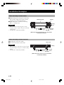
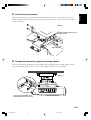
Installing the Projector
1 Mount the projector mounting adapter onto the projector.
Align the holes in the mounting adapter with the holes in the bottom of the projector, and then use the four
projector mounting screws (M6, pan head) provided to securely attach the mounting adapter to the
projector.
Caution
• Do not tighten the projector mounting screws excessively. Excessive tightening could damage the mount and cause
the projector to fall.
2 Attach the safety wire.
Use the four safety wire mounting screws (M4, pan head) provided to attach the safety wires to the
projector mounting adapter. (Use two screws on the left side and two screws on the right.) After tightening
the screws, place the wire loops around the projector’s adjusters, and then tighten the band.
Projector mounting adapter
Projector mounting screws (M6, pan head)
Bottom of the projector
Safety wire mounting screws
(M4, pan head)
Projector mounting adapter
Band
Safety wire
12PMT_BODY_E 5/29/1, 9:16 AM11

E-12
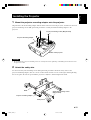
3 Install the ceiling bracket on the ceiling.
First hand-tighten the four nuts, determine the position, and then tighten the nuts securely.
(PMT-L11) (PMT-H15)
Caution
• Use M8 bolts (commercially available) to install the ceiling bracket. Using any bolts other than M8 bolts could
cause the projector to fall.
Note to Dealers and Installers
For the customer’s safety, make sure that the location where the projector is to be installed is strong
enough to bear the weight of the projector, the ceiling bracket, and the other hardware before
installing the ceiling bracket.
4 Hang the projector from the ceiling bracket.
Slide the mounting guide pin all of the way into the notch on the projector mounting adapter. This pin is
only meant to support the projector temporarily, and does not hold the projector securely. Make sure that
the projector does not fall.
(PMT-L11)
Mounting guide pin
Projector mounting adapter
Projection
direction
Projection
direction
12PMT_BODY_E 5/29/1, 9:16 AM12

E-13
English
Français
Deutsch
Svenska
Italiano
Español
Nederlands
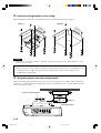
5 Install the safety brackets.
Align the safety brackets so that the mounting guide pin fits into the hole, and then use the four safety
bracket mounting screws (M4, pan head) to secure the brackets. (Use two screws on the left side and two
screws on the right.)
Safety bracket mounting screw
(M4, pan head)
Safety bracket
(PMT-L11)
6 Temporarily secure the projector mounting adapter.
Use the four vertical angle adjustment screws (M6, hexagonal head) provided to temporarily secure the
projector mounting adapter. (Use two screws on the left side and two screws on the right.)
Vertical angle adjustment screw
(Hand-tighten the other side also.)
(PMT-L11)
12PMT_BODY_E 5/29/1, 9:16 AM13

E-14
Adjusting the Projection Angle
Prior to Adjustment
• After reading the owner’s manual for the projector, turn the projector on, and project an image.
• Check the INSTALLATION item in the SETUP menu, and set the installation status. If projecting from
the front of the unit, select “FRONT/CEILING;” if projecting from the rear of the unit, select “REAR/
CEILING.”
• Select a projection size using the zoom feature, and then adjust the angle.
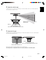
1 Adjust the horizontal angle.
Adjust the projector so that the projected image is centered horizontally on the screen, and then tighten the
horizontal angle adjustment screws.
10˚
10˚
Maximum angle of
adjustment: ±10˚
(PMT-L11)
(PMT-H15)
Horizontal angle adjustment screws
Left
Right
12PMT_BODY_E 5/29/1, 9:16 AM14

E-15
English
Français
Deutsch
Svenska
Italiano
Español
Nederlands
2 Adjust the vertical angle.
Adjust the projector so that the projected image is centered vertically on the screen, and then tighten the
four vertical angle adjustment screws.
3 Adjust the tilt angle.
Adjust the projector so that the projected image is not tilted at all compared to the screen, and then tighten
the four tilt angle adjustment screws.
15˚
15˚
Maximum angle of
adjustment: ±15˚
(PMT-L11)
Vertical angle adjustment screws
(There are also screws located on the opposite side.)
10˚ 10˚
Maximum angle of adjustment: ±10˚
(PMT-L11)
Tilt angle adjustment screws
(There are also screws located on the opposite side.)
If the projector still needs further adjustment, start over from step 1.
After adjustment is completed, make sure that the projector is secured in place.
Top
Bottom
12PMT_BODY_E 5/29/1, 9:16 AM15

E-16
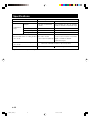
Specifications
Product Name Digital Cinema Projector Ceiling Bracket
Model No. PMT-L11 PMT-H15
Height
789 to 1359 mm (31-1/16 to 53-1/2 inch)
(variable in 30-mm (1-3/16-inch) steps)
Vertical angle ±15˚ ±15˚
Horizontal angle ±10˚ ±10˚
Tilt angle ±10˚ ±10˚
External dimensions of ceiling bracket
(w x d x h)
176 x 226 x 789 to 1359 mm
(6-15/16 x 8-7/8 x 31-1/16 to 53-1/2 inch)
(Height is variable in 30-mm
(1-3/16-inch) steps)
External dimensions of adapter
(w x d x h)
Weight 2.2 kg (4 lbs 14 oz) 4.0 kg (8 lbs 13 oz)
• Specifications are subject to change without notice.
230 x 212 x 80 mm (9-1/16 x 8-3/8 x 3-1/8 inch)
Adjustment
range
94 mm (3-11/16 inch)
(fixed)
156 x 196 x 94 mm
(6-1/8 x 7-3/4 x 3-11/16 inch)
12PMT_BODY_E 5/29/1, 9:16 AM16
-
 1
1
-
 2
2
-
 3
3
-
 4
4
-
 5
5
-
 6
6
-
 7
7
-
 8
8
-
 9
9
-
 10
10
-
 11
11
-
 12
12
-
 13
13
-
 14
14
-
 15
15
-
 16
16


på andra språk
- italiano: Yamaha H15 Manuale del proprietario
- čeština: Yamaha H15 Návod k obsluze
- español: Yamaha H15 El manual del propietario
- Deutsch: Yamaha H15 Bedienungsanleitung
- polski: Yamaha H15 Instrukcja obsługi
- português: Yamaha H15 Manual do proprietário
- français: Yamaha H15 Le manuel du propriétaire
- Türkçe: Yamaha H15 El kitabı
- English: Yamaha H15 Owner's manual
- dansk: Yamaha H15 Brugervejledning
- русский: Yamaha H15 Инструкция по применению
- suomi: Yamaha H15 Omistajan opas
- Nederlands: Yamaha H15 de handleiding
- română: Yamaha H15 Manualul proprietarului