Simplicity 2691684-00 Användarmanual
- Kategori
- Gräsklippare
- Typ
- Användarmanual
Denna manual är också lämplig för

© Briggs & Stratton, LLC
Milwaukee, WI, USA. All rights reserved.
80088447
Revision B
Not for
Reproduction

2
1
2
3
4
5
6
7
Not for
Reproduction

3
8
9
10
11
12
13
14
15
Not for
Reproduction

4
16
17
18
Not for
Reproduction

5
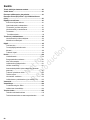
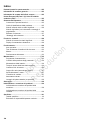
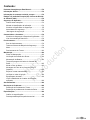
Table of Contents:
Products Covered by This Manual......................................6
General Information..............................................................6
European Office Contact Information.................................6
European Union (EU) Stage V (5): Carbon Dioxide (CO2)
Values.....................................................................................6
Operator Safety..................................................................... 6
Save these instructions.................................................... 6
Slope Identification Guide................................................ 6
Safety Symbols and Meanings.........................................6
Safety Alert Symbol and Signal Words............................ 7
Safety Decals................................................................... 7
Safety Messages.............................................................8
Features and Controls..........................................................8
Control Symbols and Meanings....................................... 8
Electronic Maintenance Display....................................... 9
Operation............................................................................. 10
Operating Area............................................................... 10
Safety Interlock System Tests........................................11
Engine.............................................................................11
Tractor Operation........................................................... 13
Maintenance.........................................................................15
Maintenance Schedule................................................... 15
Tire Pressure Check...................................................... 15
Battery Maintenance.......................................................15
Mower Blade Stop Time.................................................16
Change the Engine Oil...................................................16
Air Filter Assembly (Cartridge with pre-cleaner).............16
Push the Tractor By Hand............................................. 16
Check the Spark Plugs.................................................. 16
Towed Equipment...........................................................17
Clean the Mower Deck (if equipped)..............................17
Storage.................................................................................17
Troubleshooting..................................................................18
Troubleshooting the Rider..............................................18
Troubleshooting the Mower............................................18
Specifications......................................................................19
Specifications Chart ...................................................... 19
Power Ratings Disclaimer.............................................. 19
Not for
Reproduction

6
Products Covered by This
Manual
The products that follow are covered by this manual:
2691481-00, 2691481-01, 2691481-02, 2691487-00,
2691487-01, 2691487-02, 2691683-00, 2691684-00,
2691685-00, 2691700-00, 2691701-00, 2691702-00,
2691703-00, 2691714-00, 2691715-00
General Information
For additional information, refer to theCustomer Contact
Guideincluded with the unit.
The illustrations in this document are representative.
Your unit might look different from the images
shown.LEFTandRIGHTare referenced from the operator's
position.
The use of Important and Note in the text shows clarifications,
exceptions, or alternatives to the procedures.
All language translations of this document derive from the
initial English source file.
Recycle all packaging, used oil, and batteries according to
applicable government regulations.
European Office Contact
Information
For questions regarding European emissions, please contact
our European office at:
Max-Born-Straße 2, 68519 Viernheim, Germany.
European Union (EU) Stage
V (5): Carbon Dioxide (CO
2
)
Values
Carbon dioxide values of Briggs & Stratton
®
EU Type-
Approval Certificate engines can be found by entering CO2
into the search window on BriggsandStratton.com.
Operator Safety
Save these instructions
Save these instructions for future reference.This manual
contains safety information to make you aware of the hazards
and risks associated with the product and how to avoid them.
It also contains important instructions that must be obeyed
during the initial set-up, operation, and maintenance of the
product.
This product is designed and intended for cutting well
maintained grass and is not intended for other purposes.
It is important that you read and understand these instructions
before you attempt to start or operate this equipment.
Make sure that you are fully familiar with the controls and the
correct use of the product.
Know how to stop the unit and disengage controls quickly.
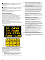
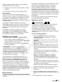
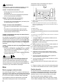
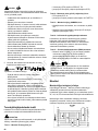
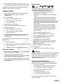
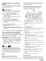
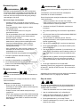
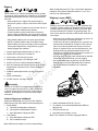
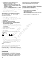
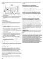
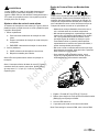
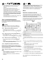
Slope Identification Guide
How to measure the slope of a lawn surface with a
smartphone or an angle finder tool:
WARNING
Do not operate on slopes greater than10degrees.
1. Use a straight edge at least two (2) feet long (A,
Figure1). A 2x4 or a straight piece of metal works well.
2. Angle finder tools.
a. Use your smartphone:Many smartphones (B,
Figure1) have an inclinometer (angle finder) located
under the compass application (app). Or, search an
app store for an Inclinometer app.
b. Use angle finder tools:Angle finder tools (C and
D, Figure1) are available at local hardware stores
or online (also called inclinometer, protractor, angle
meter, or angle gauge). Dial type (C) or digital type
(D) work, others may not.Read and obey the user
instructions supplied with the angle finder tool.
3. Put the two (2) feet long straight edge along the steepest
part of the lawn slope. Put the board up and down the
slope.
4. Lay the smartphone or angle finder tool on the straight
edge and read the angle in degrees. This is the slope of
your lawn.
Note:A paper gauge slope identification guide is included
in your product literature packet and is also available to
download from the manufacturer's website.
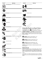
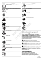
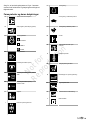
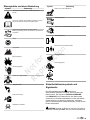
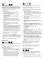
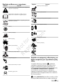
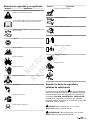
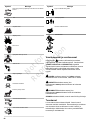
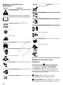
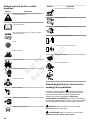
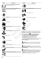
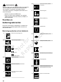
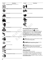
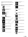
Safety Symbols and Meanings
Symbol Meaning
Safety information about hazards that can result in personal
injury.
Read and understand the Operator's Manual before you
operate or service the unit.
Not for
Reproduction

7
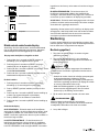
Symbol Meaning
Remove the key and read the Operator's Manual before
you service the unit.
Stop
Fire hazard
Explosion hazard
Shock hazard
Toxic fume hazard
Moving parts
Wear eye protection.
Hazardous chemical
Hot surface hazard
Amputation hazard
Thrown objects hazard
Symbol Meaning
Keep a safe distance
Keep children away
Amputation hazard
Roll-over hazard
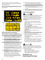
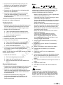
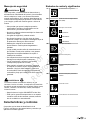
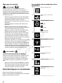
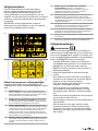
Safety Alert Symbol and Signal Words
The safety alert symbol identifies safety information
about hazards that can result in personal injury. A signal word
(DANGER,WARNING, orCAUTION) is used with the alert
symbol to indicate the likelihood and the potential severity of
injury. In addition, a hazard symbol may be used to represent
the type of hazard.
DANGERindicates a hazard which, if not
avoided,willresult in death or serious injury.
WARNINGindicates a hazard which, if not
avoided,couldresult in death or serious injury.
CAUTIONindicates a hazard which, if not
avoided,couldresult inminor or moderate injury.
NOTICEindicates information considered important but not
hazard-related.
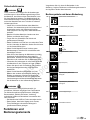
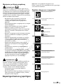
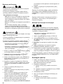
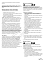
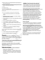
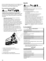
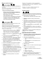
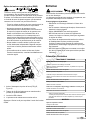
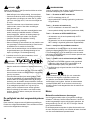
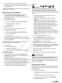
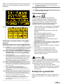
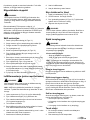
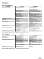
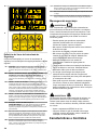
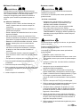
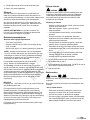
Safety Decals
Before you operate the unit, read the safety decals.Compare
Figure2to the decals shown in the table that follows. The
cautions and warnings are for your safety. To avoid personal
injury or damage to the unit, understand and obey the safety
decals.
IMPORTANT:If the safety decals become worn or damaged,
and cannot be read, order replacement decals from your local
dealer.
Not for
Reproduction

8
A
B
Safety Decal Icon Definitions
Compare the letters (A-J) in the safety decal icons to
thesafety definitions listed in the table that follows.
A WARNING:Read and understand the Operator's Manual before
you use this machine. Know the locations and functions of all
controls. Do not operate this machine unless you are trained.
B DANGER - LOSS OF TRACTION, SLIDING, STEERING
AND CONTROL ON SLOPES HAZARD:If the machine stops
forward motion or starts to move on a slope, stop the blades,
andslowlydriveoff the slope.
C DANGER - FIRE HAZARD:Make sure the unit is free of grass,
leaves, and excess oil. Do not add fuel while the engine is hot or on.
Stop the engine. Let the engine cool for at least 3 minutes before
you add fuel. Do not add fuel indoors, in an enclosed trailer, garage
or other enclosed areas. Remove spilled fuel. Do not smoke while
you operate this machine.
D DANGER - TIPPING AND SLIPPING HAZARD:Mow up and down
slopes not across. Do not operate on slopes more than 10 degrees.
Avoid sudden and sharp (fast) turns while on slopes.
E DANGER - AMPUTATION AND DISMEMBERMENT HAZARD:To
avoid injury from rotating blades and moving parts, keep safety
devices (guards, shields and switches) in place and working.
F Do not mow when children or others are around. DO NOT carry
riders especially children even with the blades off. Do not mow
in reverse unless absolutely necessary. Look down and behind –
before and while you drive the unit in reverse.
G Consult technical literature before technical repairs or maintenance.
When you leave the machine, stop the engine, set the parking
brake to the lock position, and remove the ignition key.
H Keep by-standers and children a safe distance away. Remove
objects that can be thrown by the blade. Do not mow without the
discharge chute in place.
I Do not mow without discharge chute or entire grass catcher in
place.
J To avoid injury from rotating blades, stay clear of deck edge and
keep others away.
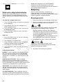
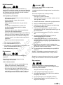
Safety Messages
WARNING
Read, understand, and obey all the instructions and
warnings in the Operator's Manual and on the machine,
engine, and attachments before you operate this machine.
Failure to obey the safety instructions in this manual and on
the equipment could result in death or serious injury.
• Only let operators who are responsible, trained and
familiar with the instructions and physically capable to
operate the machine.
• Do not operate the machine while under the influence of
alcohol or drugs.
• Wear safety glasses and closed toe footwear.
• Do not put hands or feet near rotating parts or under
the machine. Keep clear of the discharge opening at all
times.
• Keep the machine in good working order. Replace worn
or damaged parts.
• Be careful when youservice the blades. Wrap the
blades or wear gloves. Replace damaged blades. Do
not repair or alterthe blades.
• Use full width ramps when you load and unload a
machine for transport.
• See attachment or accessory for proper wheel weights
or counterweights.
• To help prevent fires, keep machine free of grass,
leaves, or other unwanted material. Clean remaining oil
or fuel spillage. Remove fuel soaked debris and let the
machine to cool before storage.
WARNING
Running engine gives off carbon monoxide, an odorless,
colorless, poison gas. Breathing carbon monoxide can
cause headaches, fatigue, dizziness, vomiting, confusion,
seizures, nausea, fainting or death.
• Operate equipment ONLY outdoors.
• Keep exhaust gas from entering a confined area
through windows, doors, ventilation intakes, or other
openings.
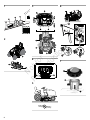
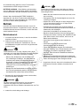
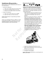
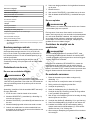
Features and Controls
Make sure that the callout letters in Figure3agree with the
features and controls listed in the table that follows.
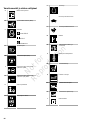
Control Symbols and Meanings
A Electronic Dash Panel
Not for
Reproduction

9
B Reverse Mowing Option (RMO)
C Ignition Switch
OFF
ON
START
D Headlight Switch
E Power Take-Off (PTO)
F Power Take-Off(PTO), Engage
Blades
G Power Take-Off (PTO), Disengage
Blades
H Cruise Control
I Parking Brake Control
J Throttle Control
K Throttle Control SLOW Position
L Throttle Control FAST Position
M Choke
N Fuel Level Gauge (if equipped)
O Ground Speed Pedals
P Seat Adjustment Lever
Q Mower Lift Lever
R Height-of-Cut Switch
S Transmission Release Lever
T Fuel Tank
U Brake Pedal
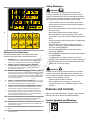
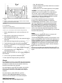
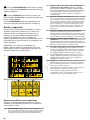
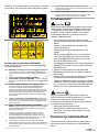
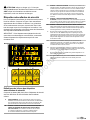
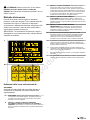
Electronic Maintenance Display
Note:When you start the unit, the Total Hours show on the
maintenance display. The total hours will set to 0 after 999.9.
Display Total Hours, Trip Hours, and Clock
1. Push MODE (A, Figure4) for less than 1 second to show
the Trip Hours.
2. Push RESET (B) for more than 3 seconds to set the Trip
Hours to 0.
Not for
Reproduction

10
3. Push MODE for less than 1 second to show the Clock.
SeeSet the Clocksection.
4. Push MODE for less than 1 second to show the Total
Hours.
Set the Clock
1. Push MODE (A, Figure4) for more than 3 seconds. The
hours will flash on the display.
2. Push RESET to adjust the hours.
3. Push MODE for less than 1 second to save the setting.
The minutes will flash on the display.
4. Push RESET to adjust the minutes.
5. Push MODE for less than 1 second to save the setting.
Maintenance Display
OIL CHANGE- This message shows after 50 hours of
operation. After you change the oil and filter, push MODE two
times to show OIL HRS. Then, push and hold MODE for 3
seconds to set the timer to zero.The display will automatically
clear.
AIR FILTER CHECK- This message shows after 25 hours of
operation. After you clean or change the air filter, push MODE
three times to show AIR FILTER HRS. Then, push and hold
MODE for 3 seconds to set the timer to zero.The display will
automatically clear.
CHANGE BLADES- This message shows after 100 hours
of operation. After you change the blade, hold the RESET
button for more than 3 seconds to set the timer to zero.The
display will automatically clear.
LOW BATTERY- This message shows when a battery
voltage problem occurs. The display will automatically clear
after servicing of the battery.
Note:The LOW BATTERY message shows on the display
before all other messages. Do the servicing ofthe battery
first. Then, do a check for other maintenance messages.
Operation
Read theOperator Safetysection before you operate this
machine. Make sure that you know the controls and how to
stop the unit.
Operating Area
1. Know the area where you plan to operate the mower.
2. Make sure that the area is free of unwanted material that
could be picked up by the blades and thrown.
DANGER
This machine is capable of throwing objects that could
injure bystanders or cause damage to buildings.
• Do not operate the machine without the entire grass
catcher, discharge chute, or other safety devices in
place and functioning properly. Check frequently for
signs of wear or deterioration and replace as needed.
• Clear the operating area of any objects which could
be thrown by or interfere with the operation of the
machine.
3. Move the rider mower outside, before you start the
engine.
WARNING
Engines give off carbon monoxide, an odorless, colorless,
poison gas. Breathing carbon monoxide can cause nausea,
fainting, or death.
4. Note all slopes and drop-offs.
DANGER
Operating on slopes, or near water, or drop-offs can result
in loss of control and roll-over.
• Mow up and down slopes not across.
• Reduce speed and be careful on slopes.
• Do not operate on slopes over 10 degrees, which is a
3.5 foot rise over a 20 foot length.
• Give yourself a minimum of two mower widths of
clearance around water, retaining walls, or drop-offs.
• Avoid mowing wet grass.
• Do not operate machine under any condition where
traction, steering, or stability is in question. Tires could
slide even if the wheels are stopped.
• Avoid starting and stopping on slopes.
• Avoid making sudden changes in speed or direction.
• Make turns slowly and gradually.
• Be careful while operating machine with a grass catcher
or other attachment(s). They can affect the stability of
the machine.
• Follow the manufacturer's recommendation for weight
limits for towed equipment and towing on slopes.
SeeTowed Equipment.
5. Make sure that the operating area is clear of bystanders,
especially children.
Not for
Reproduction

11
DANGER
This rider mower is capable of amputating hands and feet.
• Stop the mower when children or others are near.
• Keep children out of the operating area and under the
watchful care of a responsible adult.
• Do not carry passengers, especially children, even
with the blade(s) shut off. Children can fall off and be
seriously injured or interfere with the safe machine
operation. Children who have been given rides in
the past can suddenly appear in the mowing area for
another ride and be run over or backed over by the
machine.
• Use care when approaching blind corners, shrubs,
trees, or other objects that obscure vision.
Safety Interlock System Tests
This machine is equipped with a Safety Interlock System.
Do not attempt to bypass or tamper with the switches
anddevices.
WARNING
If the machine does not pass a safety test, do not operate
the machine. See an Authorized Dealer.
Test 1 — Engine will NOT crank if:
• Power Take Off (PTO) switch is ON, OR
• Brake pedal is NOT fully pushed down (parking brake
OFF)
Test 2 — Engine will crank and start if:
• PTO switch is OFF, AND
• Brake pedal is fully pushed down (parking brake ON).
Test 3 — Engine will SHUT OFF if:
• Operator rises off seat with PTO engaged, OR
• Operator rises off seat with brake pedal NOT fully pushed
down (parking brake OFF).
Test 4 — Mower Blade Stopping TimeCheck
The mower blades and mower drive belt willcome to a
complete stop in five seconds after the PTO switch is OFF.
If the mower drive belt does not stop in five seconds, see an
Authorized Service Dealer.
Test 5 — Reverse Mowing Option (RMO) Check
• The engine will STOP when reverse travel is attempted
with the PTO switched ON and the Reverse Mowing
Option (RMO) not activated.
• The RMO light will come on when the RMO has been
activated.
DANGER
Mowing in reverse can be hazardous to bystanders. Tragic
accidents can occur if the operator is not alert to the
presence of children. DO NOT activate the Reverse Mowing
Option (RMO) if children are present. Children are often
attracted to the machine and the mowing activity.
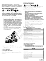
Engine
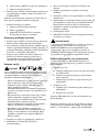
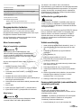
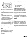
Check and Add Engine Oil
Use Briggs & Stratton
®
Warranty Certified oils for best
performance. Other high-quality detergent oils are acceptable
if classified for service SF, SG, SH, SJ or higher. Do not use
special additives.
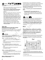
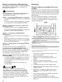
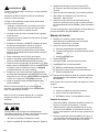
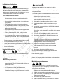
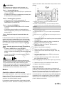
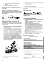
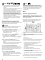
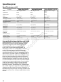
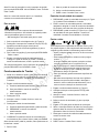
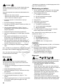
Outdoor temperatures determine the proper oil viscosity for
the engine. Use the chart to select the best viscosity for the
outdoor temperature range expected.
A SAE 30 - Below 40 °F (4 °C) the use of SAE 30 will result in hard
starting.
B 10W-30 - Above 80 °F (27 °C) the use of 10W-30 can cause increased
oil consumption. Check oil level more frequently.
C 5W-30
D Synthetic 5W-30
E
Vanguard
®
Synthetic 15W-50
*Below 40°F (4°C) the use of SAE 30 will result in hard starting.
**Above 80°F (27°C) the use of 10W-30 can cause increased oil consumption.
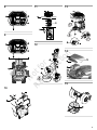
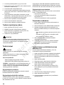
1. Put the unit on a level surface as shown in Figure5.
2. Stop the engine and remove the key. Make sure that the
oil fill area is clean.
3. Remove the dipstick (A, Figure6).Remove the remaining
oil from the dipstick.
4. Install and tighten the dipstick.
5. Remove the dipstick again, and check the oil level.
6. Make sure that the oil level is at the top of the FULL mark
(B) on the dipstick.
7. If the oil level is FULL, install and tighten the dipstick.
8. If the oil level is LOW, add oil into the oil fill tube (C).
Note:DO NOT add oil at the quick oil drain (if equipped).
9. Wait one minute, and check the oil level again.
10. Install and tighten the dipstick.
Not for
Reproduction

12
Oil Pressure
If the oil pressure is too low, a pressure switch (if equipped)
will either stop the engine or activate a warning device on the
equipment. If this occurs, stop the engine and check the oil
level with the dipstick.
If the oil level is below the ADD mark, add oil until it touches
the FULL mark. Start the engine and check for the correct oil
pressure before you operate the machine.
If the oil level is between the ADD and FULL marks,DO NOT
start the engine. Contact an Authorized Service Dealer to
correct the oil pressure.
Fuel Recommendations
Fuel must meet these requirements:
• Clean, fresh, unleaded gasoline.
• A minimum of 87 octane/87 AKI (91 RON). High altitude
use, see below.
• Gasoline with up to 10% ethanol (gasohol) is acceptable.
NOTICE Do not use unapproved gasolines, such as E15
and E85. Do not mix oil in gasoline or modify the engine to
run on alternate fuels. Use of unapproved fuels will damage
the engine components, which will not be covered under
warranty.
To protect the fuel system from gum formation, mix a fuel
stabilizer into the fuel. SeeStorage.All fuel is not the same.
If start or performance problems occur, change fuel providers
or brands. This engine is certified to operate on gasoline.
The emissions control system for carbureted engines is EM
(Engine Modifications). The emissions control systems for
engines with electronic fuel injection are ECM (Engine Control
Module), MPI (Multi Port Injection), and if equipped an O2S
(Oxygen Sensor).
High Altitude
At altitudes over 5,000 feet (1524 meters), a minimum 85
octane/85 AKI (89 RON) gasoline is acceptable.
For carbureted engines, high altitude adjustment is
required to maintain performance. Operation without this
adjustment will cause decreased performance, increased
fuel consumption, and increased emissions. Contact
a Briggs & Stratton Authorized Service Dealer for high
altitude adjustment information. Operation of the engine at
altitudes below 2,500 feet (762 meters) with the high altitude
adjustment is not recommended.
For Electronic Fuel Injection (EFI) engines, no high altitude
adjustment is necessary.
Add Fuel
WARNING
Fuel and its vapors are extremely flammable and explosive.
Always handle fuel with extreme care. Failure to Observe
these safety instructions can cause fire or explosion which
could result in severe burns or death.
When Adding Fuel
• Stop the engine and let the engine cool at least 3
minutes before you remove the fuel cap.
• Extinguish all cigarettes, cigars, pipes, and other
sources of ignition.
• Fill fuel tank outdoors or in well-ventilated area.
• Do not overfill fuel tank. To allow for expansion of the
fuel, do not fill above the bottom of the fuel tank neck.
• Keep fuel away from sparks, open flames, pilot lights,
heat, and other ignition sources.
• Check fuel lines, tank, cap, and fittings frequently for
cracks or leaks. Replace if necessary.
• If fuel spills, wait until it evaporates before you start the
engine and avoid creating any source of ignition.
• Use only an approved fuel container.
1. Remove unwanted material from the fuel cap area.
2. Remove the fuel cap (A, Figure7).
3. Fill the fuel tank (B) with fuel. DO NOT fill above the
bottom of the fuel tank neck (C).
4. Install the fuel cap.
Start the Engine
WARNING
Fuel and its vapors are extremely flammable and explosive.
Fire or explosion can cause severe burns or death.
When you start the engine:
• Make sure that spark plug, muffler, fuel cap, and air
cleaner (if equipped) are installed correctly.
• Do not crank the engine with spark plug removed.
• If the engine floods, set the choke (if equipped) to the
OPEN/RUN position, move the throttle (if equipped) to
the FAST position and crank until engine starts.
WARNING
Engines give off carbon monoxide, an odorless, colorless,
poison gas.
Breathing carbon monoxide can cause nausea, fainting, or
death.
Fire or explosion can cause severe burns or death.
• Start and operate the engine outdoors.
• Do not start or operate the engine in enclosed area,
even if doors or windows are open.
1. Check the oil level. SeeCheck and Add Engine Oil.
Not for
Reproduction

13
2. Make sure that the equipment drive controls are
disengaged.
3. Sit in the seat and lift UP the seat adjustment lever to lock
the seat in position.
4. Engage the parking brake control (I, Figure8). Push the
brake pedal, pull OUT the parking brake control, and
release the brake pedal.
5. Push the PTO switch (E) to disengage it.
6. Set the throttle/choke control (J) to the CHOKE position (if
equipped).
7. Put the key into the ignition switch (C) and turn it to the
START position. For push-button start models, push the
button two times and hold until the engine starts.
8. After the engine starts, move the throttle/choke control
to half speed. Make sure that the engine is ON for a
minimum of 30 seconds. This will warm the engine.
9. Set the throttle/choke control to the FAST position.
Note:In the event of an emergency, turn the ignition switch
to the OFF position. This will STOP the engine. SeeStop the
Engine.
Note:If the engine does not start after 2 or 3 attempts,
contact an Authorized Service Dealer.
Stop the Engine
Fuel and its vapors are extremely flammable and explosive.
Fire or explosion can cause severe burns or death.
• Do not choke the carburetor to stop the engine.
1. Release the ground speed pedals(O, Figure9).
2. Disengage the Power Take-Off (PTO) switch (E). Wait for
all moving parts to stop.
3. Move the throttle control (J)to the SLOW position.
4. Turn the ignition key switch (C) to the OFF position.
Remove the key.
5. Engage the parking brake control (I). Push the brake
pedal (U), pull UP on the parking brake control, and
release the brake pedal.
In the event of an emergency, turn the ignition switch to the
OFF position. This will STOP engine.
Tractor Operation
1. Sit in the seat and adjust the seat so that you can
comfortably reach all the controls. SeeFeatures and
Controls.
2. Engage the parking brake:
A. Fully push DOWN on the brake pedal.
B. Pull UP on the parking brake control.
C. Release the brake pedal.
3. Disengage the PTO.
4. Start the engine. SeeStart the Engine.
5. Disengage the parking brake:
A. Fully push DOWN on the brake pedal.
B. Push IN the parking brake control.
C. Release the brake pedal.
6. Push DOWN on the speed control pedal to move forward.
Release the pedal to STOP.
Note:The further down the pedal is pushed the faster the
tractor will move.
7. Stop the tractor:
A. Release the speed control pedals.
B. Set the parking brake.
C. STOP the engine. SeeStop the Engine.
Cruise Control
1. Push DOWN on the ground speed pedal (O, Figure3).
SeeFeatures and Controls.
2. When you reach the desired speed, pull UP on the cruise
control. The cruise control will lock in one of its five
locking positions.
3. Push DOWN on the brake pedal (U, Figure3) or
on the ground speed pedal to disengage the cruise
control.SeeFeatures and Controls.
Mowing
DANGER
This machine is capable of amputating hands and feet, and
throwing objects. Failure to obey the safety instructions
could result in serious injury or death.
• Only operate the machine in daylight hours or good
artificial light.
• Avoid holes, ruts, bumps, rocks, or other hidden
hazards.
Uneven terrain can overturn the machine or cause
operator to lose their balance or footing.
• Do not direct discharge material toward anyone. Avoid
discharging material against a wall or obstruction as
material may ricochet back toward the operator.
• Stop the blade(s) when crossing gravel surface.
• Do not leave a running machine unattended. Always
park on level ground, disengage the attachment, set
parking brake, stop engine and remove starter insert or
key.
1. Engage the parking brake control (I,Figure3).
2. Make sure the PTO switch (E)is disengaged.
3. Start the engine. SeeStart the Engine.
4. Set the throttle control (J)to the FAST position.
5. Engage the PTO to activate the mower blades.
6. Use the Height-of-Cut Electric Switch (R) to set the
cutting height to the desired level. SeeAdjusting the
Mower Cutting Height.
Not for
Reproduction

14
7. Disengage the parking brake control, then begin to mow.
8. Disengage the PTO.
9. STOP the engine. SeeStop the Engine.
WARNING
The engine will STOP if the reverse ground speed pedal is
depressed while the PTO is ON and the RMO has not been
activated. Always disengage the PTO OFF before tractor
operation. Sudden loss of drive could create a hazard.
Adjust the Mower Cutting Height
The mower lift lever (Q, Figure3)lowers the deck to cutting
position or raises the deck to the transport position.
1. Lower the deck:
A. Slightly pull back on the mower lift lever.
B. Push the mower lift lever to the left.
C. Push DOWN on the mower lift lever.
2. Raise the deck:
A. Pull UP on the mower lift lever.
B. Lock in the notch to the right.
Note:DO NOT cut when the deck is raised to transport
position.
Note:The height-of-cut switch(R, Figure3)controls the
mower cutting height. It adjusts the cutting height between 1.5
- 3.5 in. (2.5 - 8.89 cm). SeeSpecifications.
Reverse Mowing Option (RMO)
DANGER
Mowing in reverse can be hazardous to bystanders.
Tragic accidents can occur if the operator is not alert to
the presence of children. Children are often attracted to
the machine and the mowing activity. Never assume that
children will remain where you last saw them.
• Keep children out of the operating area and under the
watchful care of a responsible adult.
• Do not carry passengers, especially children, even
with the blade(s) shut off. Children can fall off and be
seriously injured or interfere with the safe machine
operation. Children who have been given rides in
the past can suddenly appear in the mowing area for
another ride and be run over or backed over by the
machine.
• Do not mow in reverse unless absolutely necessary.
Always look down and behind before and while
backing.
• If the machine mows in reverse without Reverse
Mowing Option activated, see an authorized dealer
immediately.
1. Engage the Power Take-Off (PTO) (E, Figure3).
2. Set the Reverse Mowing Option (RMO) key (B)to the ON
position.
3. The L.E.D. light comes on.
4. The operator mows in reverse.
Note:Remove the key to restrict access to the RMO.
Not for
Reproduction

15
Maintenance
WARNING
Unintentional sparking can result in fire or electric shock.
Unintentional start-up can result in entanglement, traumatic
amputation, or laceration.
Before adjustments and repairs:
• Disconnect the spark plug wire. Keep it away from the
spark plug.
• On electric start engines, disconnect the batteryat the
negative (-) terminal.
• Use ONLY the correct tools.
• DO NOT tamper with the governor spring, links, or other
parts to increase engine speed.
• Replacement parts must be of the same design and
installed in the same position as the original parts.
Other parts may not perform as well, may damage the
unit, and may result in injury.
• DO NOT strike the flywheel with a hammer or hard
object because the flywheel can shatter during
operation.
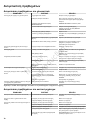
Maintenance Schedule
RIDER AND MOWER
Every 8 Hours or Daily
Check the Safety interlock system.
Remove unwanted material from the rider, mower deck, and engine
compartment.
Every 25 Hours or Annually
*
Check the tire pressure.
Check the mower blade stopping time.
Check for loose hardware on the rider and mower.
Every 50 Hours or Annually
*
Clean the battery and cables.
Check the rider brakes.
Seea Briggs & Stratton Authorized Service Dealer Annually
Lubricate the rider and mower.
Mower blades check**
*Whichever comes first.
**Check the mower blades more often in regions with sandy soils or
high dust conditions.
ENGINE
First 5 Hours
Change the engine oil.
Every 8 Hours or Daily
Check the engine oil level.
Every 25 Hours or Annually
*
Clean the air filter and pre-cleaner.**
Every 50 Hours orAnnually
*
Change the engine oil.
Replace the oil filter.
Annually
Replace the air filter.
ENGINE
Replace the pre-cleaner.
See Dealer Annually to
Inspect the muffler and spark arrester.
Replace the spark plugs.
Replace the fuel filter.
Clean the air cooling system.
*Whichever comes first.
**Clean more often in dusty conditions or when airborne material is
present.
Tire Pressure Check
For the correct traction and the best mowing performance,
make sure that the tire inflation pressure is 12-14
psi (0,82-0,96 bar). Refer to Tire Pressure Check in
theMaintenance Schedule. Also, see Tire Inflation Pressure
in theSpecificationssection.
Note:There can be a difference in tire inflation pressurefrom
the "Maximum Inflation" shown on the side of the tires.
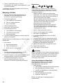
Battery Maintenance
Clean the Battery and Cables
WARNING
When you remove or install battery cables, always
disconnect the NEGATIVE (black) cable FIRST and
reconnect it LAST. If not done in this order, the positive
terminal can be shorted to the frame by a tool.
Note:DO NOT remove or connect the battery cable while the
engine is ON.
1. STOP the engine. Remove the key.
2. Disconnect the NEGATIVE (-)cables (A, Figure10) from
the battery first.
3. Disconnect the POSITIVE (+) cables (B) from the battery
last.
4. Clean the battery surface with baking soda and water.
5. Use a wire brush and terminal cleaner to to clean the
battery terminals and cable ends.
6. Lubricate the battery terminals with petroleum jelly or
non-conducting grease.
7. Install the battery.
8. Connect thePOSITIVE (+) cables to the battery first.
9. Connect thethe NEGATIVE (-)cablesto the battery last.
Charge the Battery
WARNING
Keep open flames and sparks away from the battery.
Gassesfrom the battery are very explosive.
Not for
Reproduction

16
A dead battery or one too weak to start the engine can
be the result of a defect in the charging system or other
electrical component. If there are doubts about the cause of
the problem, see an Authorized Service Dealer. To replace
the battery, seeClean the Battery and Cables.
Mower Blade Stop Time
WARNING
If the mower blade does not STOP in 5 seconds or less,the
clutch must be adjusted. DO NOT operate the machine
until the adjustment has been corrected by aBriggs &
StrattonAuthorizedService Dealer.
After the Power Take-Off (PTO) switch turns OFF, the mower
blades and mower drive belt must STOP in 5 seconds or
less.If the mower drive belt does not STOP in 5 seconds,
contact Briggs & Stratton Authorized Service Dealer for
repairs.
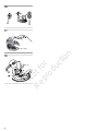
Change the Engine Oil
1. Put the rider on a level surface (A, Figure11).
2. Stop the engine and remove starter insertor key (B).
3. Clean the oil fill and filter areas.
4. Remove the dipstick(C).
5. Disconnect the oil drain hose (A,Figure12)
6. Carefully remove the cap (B),and lower the hose into an
approved container (C).
7. After the oil has drained, installthe cap tightly, then attach
the hose to the side of the engine.
8. Remove the oil filter (B, Figure13) and discard.
9. Lightly lubricate the oil filter gasket (A) with clean oil.
10. Install the oil filter by hand until the gasket touches the
oil filter adapter (C). Then, tighten the oil filter 1/2 to 3/4
turns.
11. Add oil.Refer to theCheck and Add Oilsection.
Air Filter Assembly (Cartridge with pre-
cleaner)
WARNING
DO NOT start or operate the engine without an air cleaner
assembly or air filter as it is a fire hazard.
NOTICE DO NOT use pressurized air or solvents to clean
the air filter. Pressurized air can damage the filter and
solvents will dissolve it.
1. Loosen the fasteners (A, Figure14) and remove the
cover (B).
2. Remove the air cleaner assembly (C) and disassemble it.
3. Remove unwanted material or debris that can get into the
carburetor throat (D).
4. Remove the pre-cleaner from the air filter.
5. Lightly tap the air filter on a hard surface to loosen debris.
If the air filter is dirty, replace it.
6. Soak the pre-cleaner in liquid detergent and water. Let it
fully air dry. DO NOT lubricate the pre-cleaner.
7. Assemble the dry pre-cleaner to the air filter.
8. Install the air filter assembly.
9. Install the cover and tighten the fasteners.
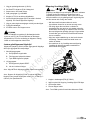
Push the Tractor By Hand
1. Disengage the Power-Take-Off (PTO) (E, Figure3).
2. STOP the engine. SeeStop the Engine.
3. Pull the transmission release lever (S, Figure15). Then,
push the lever down to lock in position.
4. The rider can be pushed by hand.
WARNING
Towing the unit will cause transmission damage. Do not use
another vehicle to push or pull this unit. Do not actuate the
transmission release lever while the engine is ON.
Check the Spark Plugs
WARNING
Unintentional sparking can result in fire or electric shock.
Unintentional start-up can result in entanglement, traumatic
amputation, or laceration.
When you test for spark:
• Use an approved spark plug tester.
• DO NOT check for spark with the spark plug removed.
NOTICE Spark plugs have different heat ranges. It is
important that the correct spark plug is used, otherwise,
engine damage can occur. Replace the spark plug with the
same type or equivalent one.
Clean the Spark Plugs
Clean the spark plugswith a wire brush and sturdy knife. DO
NOT use abrasives.
Check the Spark Plug Gap
Use a spark plug feeler gauge (A,Figure16) to check the
gap between the two electrodes. When the gap is correct, the
gauge will drag slightly as you pull it through the gap.
To adjust the spark plug gap, use a spark plug gauge and
gently bend the curved electrode. Make sure that you do not
touch the center electrode or the porcelain.
Install the Spark Plugs
Tighten the spark plug with your fingers, and then, tighten it
with a wrench as shown in Figure 17.
• 180 in-lbs (20 Nm), OR
• 1/2 turn when you install the original spark plug, OR
• 1/4 turn when you install a new spark plug.
Not for
Reproduction

17
Towed Equipment
1. Before you tow the unit, make sure that the hitch is
designed for towing.
2. Attach towed equipment ONLY at the hitch point.
3. For towed equipment and towing on slopes, make sure
that the weight limit recommendationsare correct.
• Gross weight (trailer and load) of 400 lb (181.4 kg).
• Maximum of 20 lb (9.1 kg) foot up or down on the
tongue.
• Go from a 10° limit to a 5°limit on slopes.
4. DO NOT let children or others in or on towed equipment.
5. The weight of the towed equipment on slopes can cause
loss of traction and loss of control.
6. DO NOT shift to neutral and coast down hill.
Clean the Mower Deck (if equipped)
Note:Use the washout port (C, Figure18) to clean the bottom
of the mower deck.
1. Put the rider on a smooth level surface.
2. Attach the quick disconnect (A,Figure18)to the garden
hose (B) and then connect to the washout port (C)on the
mower deck.
3. Turn the water ON.
4. Start the engine. SeeStart the Engine.
5. Set the Height-of-Cut to the highest position. SeeAdjust
the Mower Cutting Height.
6. Engage the Power Take-Off (PTO) to activate the mower
blades.The rotation of the blades and the water will clean
the bottom of the mower deck.
7. Disengage the PTO.
8. Stop the engine. SeeStop the Engine.
9. Turn the water OFF.
10. Remove the garden hose and quick disconnect from the
washout port (C).
Storage
WARNING
Never store the unit (with fuel) in an enclosed, non-
ventilated structure. Fuel vapors can travel to an ignition
source (such as a furnace, water heater, etc.) and cause an
explosion.
• Store away from furnaces, stoves, water heaters, or
other appliances that have pilot lights or other ignition
sources because they can ignite fuel vapors.
Equipment
Turn OFF the Power Take-Off (PTO), and set the parking
brake. Remove the starter insert.Let the machine cool.
If you remove the battery, the battery life will increase. Make
sure that thebattery is in a cool, and dry location, and keep
it fully charged. If the battery is left in the unit, disconnect the
negative cable.
Fuel System
Fuel can become stale when kept in a storage container
for more than 30 days. Each time you fill the container
with fuel, addfuel stabilizerto the fuel as specified by the
manufacturer’s instructions. This keeps fuel fresh and
decreases fuel-related problems or contamination in the fuel
system.
It is not necessary to drain fuel from the engine whenfuel
stabilizeris added as instructed. Before storage, turn the
engine ON for 2 minutes to move the fuel and stabilizer
through the fuel system.
Before starting the machine after it has been stored:
• Check all fluid levels. Check all maintenance items.
• Do all recommended checks and procedures found in this
manual.
• Make sure the engine is warm before you use it.
Not for
Reproduction

18
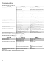
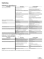
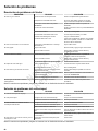
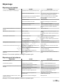
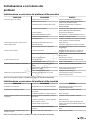
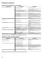
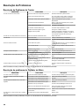
Troubleshooting
Troubleshooting the Rider
PROBLEM LOOK FOR REMEDY
The brake pedal is not pushed down. Fully push down on the brake pedal.
The fuel tank is empty. If engine is hot, let it cool, and then fill the fuel tank
again.
The PTO switch is in ON position. Set the PTO switch to the OFF position.
The cruise control is engaged. Set the cruise control to the NEUTRAL/OFF
position.
The engine is flooded. Disengage the choke.
The battery terminals are dirty. Refer toClean the Battery and Cables.
The battery is discharged or dead. Charge or replace the battery.
The engine will not turn over or start.
Loose or broken wiring. Visually check wiring. If wires are frayed or broken,
see an Authorized Service Dealer.
The engine starts hard or runs poorly. The fuel mixture is too rich. Clean the air filter.
Low oil level. Check and add oil as required.The engine knocks.
Incorrect grade of oil. Refer to theCheck and Add Engine Oilsection.
The engine is too hot. Check the engine fins, blower screen, and air
cleaner (if equipped).
Incorrect grade of oil. Refer to theCheck and Add Engine Oilsection.
Excessive oil consumption.
Too much oil in crankcase. Drain excess oil.
The air filter is dirty. Refer to theAir Filter Assemblysection.The engine exhaust is black.
The choke is closed. Open the choke.
The speed control pedals are not pushed down. Push down on the speed control pedals.
The transmission release lever is in the PUSH
position.
Move the transmission release lever to the DRIVE
position.
The engine runs, but the rider will not drive.
The parking brake is engaged. Disengage the parking brake.
The rider steers hard or handles poorly. Incorrect tire inflation. Refer to theCheck Tire Pressuresection.
Note:For all other problems, contact an Authorized Service Dealer.
Troubleshooting the Mower
PROBLEM LOOK FOR REMEDY
The mower cut is uneven. The tires are not correctly inflated. Refer to theTire Pressure Checksection.
The engine speed is too slow. Set to FAST throttle.The mower cut looks rough.
The ground speed is too fast. Slow down.
The engine speed is too slow. Set to FAST throttle.
The ground speed is too fast. Slow down.
Dirty or clogged air cleaner. Refer to theAir Filter Assemblysection.
Height-of-Cut is set too low. Cut tall grass at maximum Height-of-Cut during first
pass.
The engine stalls easily with the mower engaged.
The engine is not at the operating temperature. START the engine,and let it warmfor several
minutes.
The engine starts, and the rider drives, but the
mower will not cut.
The Power-Take Off (PTO) is disengaged. Engage the PTO.
Note:For all other problems, contact an Authorized Service Dealer.
Not for
Reproduction

19
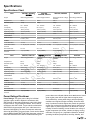
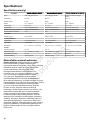
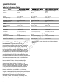
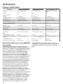
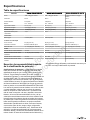
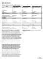
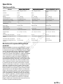
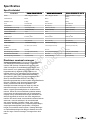
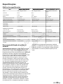
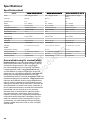
Specifications
Specifications Chart
Item
2691481, 2691487,
2691683
2691482,
2691488, 2691576
2691483, 2691489 2691714
Engine Intek™Briggs & Stratton Intek™Briggs & Stratton Professional Series™Briggs
& Stratton
Intek™Briggs & Stratton
Displacement 656 cc 656 cc 725 cc 656 cc
Electrical System 9-Amp 9-Amp 9-Amp 9-Amp
Battery 12V - 195CCA 12V - 195CCA 12V - 230CCA 12V - 195CCA
Oil Capacity 64 oz (1,9 L) 64 oz (1,9 L) 64 oz (1,9L) 64 oz (1,9L)
Spark Plug Gap .030 in (,76 mm) .030 in (,76 mm) .030 in (,76 mm) .030 in (,76 mm)
Spark Plug Torque 180 lb-in (20 Nm) 180 lb-in (20 Nm) 180 lb-in (20 Nm) 180 lb-in (20 Nm)
Fuel Tank Capacity 13.2 L 13.2 L 13.2 L 11 L
Transmission
Make and Type
Tuff Torq
®
K46 Tuff Torq
®
K46 Tuff Torq
®
K46 Tuff Torq
®
K46
Chassis
Front Wheel Size 15 x 6-6 15 x 6-6 15 x 6-6 15 x 6-6
Front Wheel Inflation
Pressure
12 - 14 psi (0,82 - 0,92 Bar) 12 - 14 psi (0,82 - 0,92 Bar) 12 - 14 psi (0,82 - 0,92 Bar) 12 - 14 psi (0,82 - 0,92 Bar)
Rear Wheel Size 20 x 8-8 22 x 10-8 22 x 9.5-12 20 x 8-8
Rear Wheel Inflation
Pressure
10 psi (0,68 Bar) 10 psi (0,68 Bar) 10 psi (0,68 Bar) 10 psi (0,68 Bar)
Item 2691701, 2691715 2691684, 2691702 2691685, 2691703 2691700
Engine Intek™Briggs & Stratton Professional Series™Briggs
& Stratton
Professional Series™Briggs
& Stratton
Intek™Briggs & Stratton
Displacement 656 cc 725 cc 725 cc 656 cc
Electrical System 9-Amp 9-Amp 9-Amp 9-Amp
Battery 12V - 195CCA 12V - 230CCA 12V - 230CCA 12V - 195CCA
Oil Capacity 64 oz (1,9 L) 64 oz (1,9 L) 64 oz (1,9 L) 64 oz (1,9 L)
Spark Plug Gap .030 in (,76 mm) .030 in (,76 mm) .030 in (,76 mm) .030 in (,76 mm)
Spark Plug Torque 180 lb-in (20 Nm) 180 lb-in (20 Nm) 180 lb-in (20 Nm) 180 lb-in (20 Nm)
Fuel Tank Capacity 11 L 11 L 11 L 11 L
Transmission
Make and Type
Tuff Torq
®
K46 Tuff Torq
®
K46 Tuff Torq
®
K46 Tuff Torq
®
K46
Chassis
Front Wheel Size 15 x 6-6 15 x 6-6 15 x 6-6 15 x 6-6
Front Wheel Inflation
Pressure
12 - 14 psi (0,82 - 0,92 Bar) 12 - 14 psi (0,82 - 0,92 Bar) 12 - 14 psi (0,82 - 0,92 Bar) 12 - 14 psi (0,82 - 0,92 Bar)
Rear Wheel Size 22 x 10-8 22 x 9.5-12 22 x 9.5-12 20 x 10-8
Rear Wheel Inflation
Pressure
10 psi (0,68 Bar) 10 psi (0,68 Bar) 10 psi (0,68 Bar) 10 psi (0,68 Bar)
Power Ratings Disclaimer
Power Ratings:The gross power rating for individual
gasoline engine models is labeled in accordance with
SAE (Society of Automotive Engineers) code J1940 Small
Engine Power & Torque Rating Procedure, and is rated in
accordance with SAE J1995. Torque values are derived at
2600 RPM for those engines with “rpm” called out on the
label and 3060 RPM for all others; horsepower values are
derived at 3600 RPM. The gross power curves can be viewed
at www.BRIGGSandSTRATTON.COM. Net power values are
taken with exhaust and air cleaner installed whereas gross
power values are collected without these attachments. Actual
gross engine power will be higher than net engine power
and is affected by, among other things, ambient operating
conditions and engine-to-engine variability. Given the wide
array of products on which engines are placed, the gasoline
engine may not develop the rated gross power when used in
a given piece of power equipment. This difference is due to
a variety of factors including, but not limited to, the variety of
engine components (air cleaner, exhaust, charging, cooling,
carburetor, fuel pump, etc.), application limitations, ambient
operating conditions (temperature, humidity, altitude), and
Not for
Reproduction

20
engine-to-engine variability. Due to manufacturing and
capacity limitations, Briggs & Stratton may substitute an
engine of higher rated power for this engine.
Not for
Reproduction
Sidan laddas...
Sidan laddas...
Sidan laddas...
Sidan laddas...
Sidan laddas...
Sidan laddas...
Sidan laddas...
Sidan laddas...
Sidan laddas...
Sidan laddas...
Sidan laddas...
Sidan laddas...
Sidan laddas...
Sidan laddas...
Sidan laddas...
Sidan laddas...
Sidan laddas...
Sidan laddas...
Sidan laddas...
Sidan laddas...
Sidan laddas...
Sidan laddas...
Sidan laddas...
Sidan laddas...
Sidan laddas...
Sidan laddas...
Sidan laddas...
Sidan laddas...
Sidan laddas...
Sidan laddas...
Sidan laddas...
Sidan laddas...
Sidan laddas...
Sidan laddas...
Sidan laddas...
Sidan laddas...
Sidan laddas...
Sidan laddas...
Sidan laddas...
Sidan laddas...
Sidan laddas...
Sidan laddas...
Sidan laddas...
Sidan laddas...
Sidan laddas...
Sidan laddas...
Sidan laddas...
Sidan laddas...
Sidan laddas...
Sidan laddas...
Sidan laddas...
Sidan laddas...
Sidan laddas...
Sidan laddas...
Sidan laddas...
Sidan laddas...
Sidan laddas...
Sidan laddas...
Sidan laddas...
Sidan laddas...
Sidan laddas...
Sidan laddas...
Sidan laddas...
Sidan laddas...
Sidan laddas...
Sidan laddas...
Sidan laddas...
Sidan laddas...
Sidan laddas...
Sidan laddas...
Sidan laddas...
Sidan laddas...
Sidan laddas...
Sidan laddas...
Sidan laddas...
Sidan laddas...
Sidan laddas...
Sidan laddas...
Sidan laddas...
Sidan laddas...
Sidan laddas...
Sidan laddas...
Sidan laddas...
Sidan laddas...
Sidan laddas...
Sidan laddas...
Sidan laddas...
Sidan laddas...
Sidan laddas...
Sidan laddas...
Sidan laddas...
Sidan laddas...
Sidan laddas...
Sidan laddas...
Sidan laddas...
Sidan laddas...
Sidan laddas...
Sidan laddas...
Sidan laddas...
Sidan laddas...
Sidan laddas...
Sidan laddas...
Sidan laddas...
Sidan laddas...
Sidan laddas...
Sidan laddas...
Sidan laddas...
Sidan laddas...
Sidan laddas...
Sidan laddas...
Sidan laddas...
Sidan laddas...
Sidan laddas...
Sidan laddas...
Sidan laddas...
Sidan laddas...
Sidan laddas...
Sidan laddas...
Sidan laddas...
Sidan laddas...
Sidan laddas...
Sidan laddas...
Sidan laddas...
Sidan laddas...
Sidan laddas...
Sidan laddas...
Sidan laddas...
Sidan laddas...
Sidan laddas...
Sidan laddas...
Sidan laddas...
Sidan laddas...
Sidan laddas...
Sidan laddas...
Sidan laddas...
Sidan laddas...
Sidan laddas...
Sidan laddas...
Sidan laddas...
Sidan laddas...
Sidan laddas...
Sidan laddas...
Sidan laddas...
Sidan laddas...
Sidan laddas...
Sidan laddas...
Sidan laddas...
Sidan laddas...
Sidan laddas...
Sidan laddas...
Sidan laddas...
Sidan laddas...
Sidan laddas...
Sidan laddas...
Sidan laddas...
Sidan laddas...
Sidan laddas...
Sidan laddas...
Sidan laddas...
Sidan laddas...
Sidan laddas...
Sidan laddas...
Sidan laddas...
Sidan laddas...
Sidan laddas...
Sidan laddas...
Sidan laddas...
Sidan laddas...
Sidan laddas...
Sidan laddas...
Sidan laddas...
Sidan laddas...
Sidan laddas...
Sidan laddas...
Sidan laddas...
Sidan laddas...
Sidan laddas...
Sidan laddas...
Sidan laddas...
Sidan laddas...
Sidan laddas...
Sidan laddas...
Sidan laddas...
Sidan laddas...
Sidan laddas...
Sidan laddas...
Sidan laddas...
Sidan laddas...
-
 1
1
-
 2
2
-
 3
3
-
 4
4
-
 5
5
-
 6
6
-
 7
7
-
 8
8
-
 9
9
-
 10
10
-
 11
11
-
 12
12
-
 13
13
-
 14
14
-
 15
15
-
 16
16
-
 17
17
-
 18
18
-
 19
19
-
 20
20
-
 21
21
-
 22
22
-
 23
23
-
 24
24
-
 25
25
-
 26
26
-
 27
27
-
 28
28
-
 29
29
-
 30
30
-
 31
31
-
 32
32
-
 33
33
-
 34
34
-
 35
35
-
 36
36
-
 37
37
-
 38
38
-
 39
39
-
 40
40
-
 41
41
-
 42
42
-
 43
43
-
 44
44
-
 45
45
-
 46
46
-
 47
47
-
 48
48
-
 49
49
-
 50
50
-
 51
51
-
 52
52
-
 53
53
-
 54
54
-
 55
55
-
 56
56
-
 57
57
-
 58
58
-
 59
59
-
 60
60
-
 61
61
-
 62
62
-
 63
63
-
 64
64
-
 65
65
-
 66
66
-
 67
67
-
 68
68
-
 69
69
-
 70
70
-
 71
71
-
 72
72
-
 73
73
-
 74
74
-
 75
75
-
 76
76
-
 77
77
-
 78
78
-
 79
79
-
 80
80
-
 81
81
-
 82
82
-
 83
83
-
 84
84
-
 85
85
-
 86
86
-
 87
87
-
 88
88
-
 89
89
-
 90
90
-
 91
91
-
 92
92
-
 93
93
-
 94
94
-
 95
95
-
 96
96
-
 97
97
-
 98
98
-
 99
99
-
 100
100
-
 101
101
-
 102
102
-
 103
103
-
 104
104
-
 105
105
-
 106
106
-
 107
107
-
 108
108
-
 109
109
-
 110
110
-
 111
111
-
 112
112
-
 113
113
-
 114
114
-
 115
115
-
 116
116
-
 117
117
-
 118
118
-
 119
119
-
 120
120
-
 121
121
-
 122
122
-
 123
123
-
 124
124
-
 125
125
-
 126
126
-
 127
127
-
 128
128
-
 129
129
-
 130
130
-
 131
131
-
 132
132
-
 133
133
-
 134
134
-
 135
135
-
 136
136
-
 137
137
-
 138
138
-
 139
139
-
 140
140
-
 141
141
-
 142
142
-
 143
143
-
 144
144
-
 145
145
-
 146
146
-
 147
147
-
 148
148
-
 149
149
-
 150
150
-
 151
151
-
 152
152
-
 153
153
-
 154
154
-
 155
155
-
 156
156
-
 157
157
-
 158
158
-
 159
159
-
 160
160
-
 161
161
-
 162
162
-
 163
163
-
 164
164
-
 165
165
-
 166
166
-
 167
167
-
 168
168
-
 169
169
-
 170
170
-
 171
171
-
 172
172
-
 173
173
-
 174
174
-
 175
175
-
 176
176
-
 177
177
-
 178
178
-
 179
179
-
 180
180
-
 181
181
-
 182
182
-
 183
183
-
 184
184
-
 185
185
-
 186
186
-
 187
187
-
 188
188
-
 189
189
-
 190
190
-
 191
191
-
 192
192
-
 193
193
-
 194
194
-
 195
195
-
 196
196
-
 197
197
-
 198
198
-
 199
199
-
 200
200
-
 201
201
-
 202
202
-
 203
203
-
 204
204
-
 205
205
-
 206
206
-
 207
207
-
 208
208


Simplicity 2691684-00 Användarmanual
- Kategori
- Gräsklippare
- Typ
- Användarmanual
- Denna manual är också lämplig för
på andra språk
- italiano: Simplicity 2691684-00 Manuale utente
- español: Simplicity 2691684-00 Manual de usuario
- Deutsch: Simplicity 2691684-00 Benutzerhandbuch
- português: Simplicity 2691684-00 Manual do usuário
- français: Simplicity 2691684-00 Manuel utilisateur
- English: Simplicity 2691684-00 User manual
- dansk: Simplicity 2691684-00 Brugermanual
- suomi: Simplicity 2691684-00 Ohjekirja
- Nederlands: Simplicity 2691684-00 Handleiding
Relaterade papper
-
Snapper 2691487 Användarmanual
-
Simplicity TRACTOR, RDLT Användarmanual
-
-
Simplicity 2691049 Användarmanual
-
-
-
Simplicity TRACTOR, EURO, RDLT Användarmanual
-
Simplicity RIDER, SPX, SNAPPER Användarmanual
-
-