
SPEAKER SYSTEMS
SV10/SV12/SV15
SV12M
Owner’s Manual
Mode d’emploi
Bedienungsanleitung
Manual de instrucciónes
Thank you for purchasing a YAMAHA product. To obtain
maximum performance from your YAMAHA speaker system
and ensure many years of trouble-free operation, we recommend
that you read this Owner’s Manual thoroughly before use.
Contents
Precautions ...................................................................... 2
Connecting the Speakers ................................................ 4
Specifications ................................................................... 5

Precautions
To protect your speakers
When choosing a power amplifier to use with your speakers, make sure that its power output matches the speakers’ power
capacity (refer to the Specifications on page 5). Even if the amplifier’s power output is lower than the speakers’ PGM
(program) power capacity, the speakers may be damaged when clipping of a high input signal occurs.
The following may cause damage to speakers:
• Feedback caused when using a microphone.
• Continuous high sound pressure level produced by electronic instruments.
• Continuous high-power output distorted signals.
• Popping noises caused by turning on equipment, or by connecting or disconnecting system components while the amplifier
is turned on.
AVOID EXCESSIVE HEAT, HUMIDITY, DUST AND VI-
BRATION
When choosing a location for your speakers, avoid the fol-
lowing:
• Direct sunlight, high temperatures (such as near heat-
ers), or excessively low temperatures.
• High humidity.
• Areas subject to excessive dust accumulation and vibra-
tion.
• Non-level or unstable surfaces.
HOW TO POWER UP YOUR SOUND SYSTEM
To avoid damage to your speakers and other parts of your
system, when you turn on your system, ALWAYS turn the
power amp on last! This will avoid loud, damaging pops
that will annoy your audience, and blow your speakers.
When you power down, the amplifier should ALWAYS be
turned off first to avoid the same problems.
MAKE SURE THE POWER IS OFF BEFORE MAKING
OR REMOVING CONNECTIONS
Always turn the power switches of system components
OFF prior to connecting or disconnecting cables. Failure to
do so may result in damage to speakers as well as to con-
nected equipment.
DISCONNECT CABLES BEFORE MOVING THE SYS-
TEM
To prevent short circuits or breakage of cables, always dis-
connect cables prior to moving system equipment.
MATCH CONNECTOR POLARITY
When using two or more speaker systems, be sure match
the polarity (+/–) of the speaker system connectors to those
at the amplifier. If the polarities do not match, the sounds
produced by the speakers will interfere with each other,
making it impossible to achieve a well-balanced sound
field.
KEEP THIS OWNER’S MANUAL IN A SAFE PLACE
FOR FUTURE REFERENCE

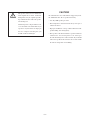
CAUTION!
Recommended for use with Ultimate Support Systems,
Inc. Model TS-30 or TS-33 speaker stands only.
• Use only ONE speaker per stand.
• The loudspeakers and stands must always rest upon a
solid, level surface.
• Improper installation or usage could result in the loud-
speaker falling and causing injury.
• The top tube of the TS-30 and TS-33 speaker stands has
a diameter of 1-1/2", but is tapered to 1-3/8" at the top to
fit in the mounting holes on these models. If you should
remove the top tube from a stand, be sure to insert it with
the narrow end up when reassembling.
This product, when used in combination
with amplification and/or additional
loudspeakers, may be capable of produc-
ing sound levels that could cause perma-
nent hearing loss.
DO NOT operate at high volume levels
or at a level that is uncomfortable. If you
experience any discomfort or ringing in
the ears, or suspect an hearing loss, you
should consult an audiologist.

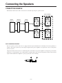
Connecting the Speakers
CONNECTION EXAMPLE
The illustration below shows audio connections for a standard setup using two speaker systems.
DAISY-CHAINING SPEAKERS
Since the speaker systems in this series are equipped with two input terminals that are internally connected in parallel, it is
possible “daisy-chain” speakers by connecting the output from the power amplifier to one phone jack, and a second speaker
system to the other.
All speaker models in this series have a nominal impedance of 8Ω. Since most power amplifiers are designed to provide stable
performance at a load impedance of 4 or 8Ω, Yamaha recommends that no more than two 8Ω speaker systems be daisy-chained
together. This will allow the amplifier to operate properly and avoid overheating.

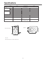
120˚
30˚
75˚
105˚
Model SV10 SV12/SV12M SV15
Enclosure Bass reflex type
Speaker Unit LF 10" cone 12" cone 15" cone
HF Piezo horn
Frequency Response 70 Hz to 20 kHz 60 Hz to 20 kHz 50 Hz to 20 kHz
Power Capacity NOISE 75 W 100 W
PGM 150 W 200 W
MAX 300 W 400 W
Nominal Impedance 8Ω
Sensitivity 95 dB SPL (1W, 1m) 97 dB SPL (1W, 1m) 98 dB SPL (1W, 1m)
Input Connectors 1/4" phone jack x 2 (parallel input)
Dimensions (W x H x D) 400 x 517 x 328 mm SV12: 445 x 525 x 372 mm 510 x 628 x 455 mm
SV12M: 525 x 445 x 315 mm
Weight 13.3 kg SV12: 14.8 kg 22 kg
SV12M: 13.5 kg
Specifications
Unit: mm
Specifications subject to change without notice

P.O. Box 1, Hamamatsu, Japan
-
 1
1
-
 2
2
-
 3
3
-
 4
4
-
 5
5
-
 6
6


Yamaha SV10 Användarmanual
- Kategori
- Högtalare
- Typ
- Användarmanual
på andra språk
- italiano: Yamaha SV10 Manuale utente
- čeština: Yamaha SV10 Uživatelský manuál
- español: Yamaha SV10 Manual de usuario
- Deutsch: Yamaha SV10 Benutzerhandbuch
- polski: Yamaha SV10 Instrukcja obsługi
- português: Yamaha SV10 Manual do usuário
- français: Yamaha SV10 Manuel utilisateur
- Türkçe: Yamaha SV10 Kullanım kılavuzu
- English: Yamaha SV10 User manual
- dansk: Yamaha SV10 Brugermanual
- русский: Yamaha SV10 Руководство пользователя
- Nederlands: Yamaha SV10 Handleiding
- română: Yamaha SV10 Manual de utilizare