Yamaha Tio1608 Bruksanvisning
- Kategori
- Musikutrustning
- Typ
- Bruksanvisning
Denna manual är också lämplig för

JA
ES
RU
IT
PT
FR
DE
EN
Owner’s Manual
Bedienungsanleitung
Mode d’emploi
Manual de instrucciones
Manual do Proprietário
Manuale di istruzioni
Руководство пользователя
AUDIO INTERFACE
EnglishDeutschFrançaisEspañolPortuguêsItalianoРусский
Tio1608-D
I/O RACK

Owner’s Manual
Tio1608-D
-
2
-
The above warning is located on the rear of the unit.
L’avertissement ci-dessus est situé sur l’arrière de l’unité.
Explanation of Graphical Symbols
Explication des symboles
The lightning flash with arrowhead symbol within an equilateral triangle is intended to alert the user to the presence of uninsulated
“dangerous voltage” within the product’s enclosure that may be of sufficient magnitude to constitute a risk of electric shock to persons.
L’éclair avec une flèche à l’intérieur d’un triangle équilatéral est destiné à attirer l’attention de l’utilisateur sur la présence d’une «
tension dangereuse » non isolée à l’intérieur de l’appareil, pouvant être suffisamment élevée pour constituer un risque d’électrocution.
The exclamation point within an equilateral triangle is intended to alert the user to the presence of important operating and maintenance
(servicing) instructions in the literature accompanying the product.
Le point d’exclamation à l’intérieur d’un triangle équilatéral est destiné à attirer l’attention de l’utilisateur sur la présence d’instructions
importantes sur l’emploi ou la maintenance (réparation) de l’appareil dans la documentation fournie.
IMPORTANT SAFETY
INSTRUCTIONS
1 Read these instructions.
2 Keep these instructions.
3 Heed all warnings.
4 Follow all instructions.
5 Do not use this apparatus near water.
6 Clean only with dry cloth.
7 Do not block any ventilation openings. Install in accordance with
the manufacturer’s instructions.
8 Do not install near any heat sources such as radiators, heat
registers, stoves, or other apparatus (including amplifiers) that
produce heat.
9 Do not defeat the safety purpose of the polarized or grounding-
type plug. A polarized plug has two blades with one wider than the
other. A grounding type plug has two blades and a third grounding
prong. The wide blade or the third prong are provided for your
safety. If the provided plug does not fit into your outlet, consult an
electrician for replacement of the obsolete outlet.
10 Protect the power cord from being walked on or pinched
particularly at plugs, convenience receptacles, and the point
where they exit from the apparatus.
11 Only use attachments/accessories specified by the manufacturer.
12 Use only with the cart, stand, tripod, bracket, or
table specified by the manufacturer, or sold
with the apparatus. When a cart is used, use
caution when moving the cart/apparatus
combination to avoid injury from tip-over.
13 Unplug this apparatus during lightning storms
or when unused for long periods of time.
14 Refer all servicing to qualified service personnel. Servicing is
required when the apparatus has been damaged in any way, such
as power-supply cord or plug is damaged, liquid has been spilled
or objects have fallen into the apparatus, the apparatus has been
exposed to rain or moisture, does not operate normally, or has
been dropped.
PRÉCAUTIONS CONCER-
NANT LA SÉCURITÉ
1 Lire ces instructions.
2 Conserver ces instructions.
3 Tenir compte de tous les avertissements.
4 Suivre toutes les instructions.
5 Ne pas utiliser ce produit à proximité d’eau.
6 Nettoyer uniquement avec un chiffon propre et sec.
7 Ne pas bloquer les orifices de ventilation. Installer l’appareil
conformément aux instructions du fabricant.
8
Ne pas installer l’appareil à proximité d’une source de chaleur
comme un radiateur, une bouche de chaleur, un poêle ou tout autre
appareil (y compris un amplificateur) produisant de la chaleur.
9 Ne pas modifier le système de sécurité de la fiche polarisée ou de
la fiche de terre. Une fiche polarisée dispose de deux broches dont
une est plus large que l’autre. Une fiche de terre dispose de deux
broches et d’une troisième pour le raccordement à la terre. Cette
broche plus large ou cette troisième broche est destinée à assurer
la sécurité de l’utilisateur. Si la fiche équipant l’appareil n’est pas
compatible avec les prises de courant disponibles, faire remplacer
les prises par un électricien.
10 Acheminer les cordons d’alimentation de sorte qu’ils ne soient pas
piétinés ni coincés, en faisant tout spécialement attention aux
fiches, prises de courant et au point de sortie de l’appareil.
11 Utiliser exclusivement les fixations et accessoires spécifiés par le
fabricant.
12 Utiliser exclusivement le chariot, le stand, le
trépied, le support ou la table recommandés par
le fabricant ou vendus avec cet appareil. Si
l’appareil est posé sur un chariot, déplacer le
chariot avec précaution pour éviter tout risque
de chute et de blessure.
13 Débrancher l’appareil en cas d’orage ou
lorsqu’il doit rester hors service pendant une période prolongée.
14 Confier toute réparation à un personnel qualifié. Faire réparer
l’appareil s’il a subi tout dommage, par exemple si la fiche ou le
cordon d’alimentation est endommagé, si du liquide a coulé ou
des objets sont tombés à l’intérieur de l’appareil, si l’appareil a été
exposé à la pluie ou à de l’humidité, si l’appareil ne fonctionne pas
normalement ou est tombé.
WARNING
TO REDUCE THE RISK OF FIRE OR ELECTRIC SHOCK, DO NOT
EXPOSE THIS APPARATUS TO RAIN OR MOISTURE.
(UL60065_03)
AVERTISSEMENT
POUR RÉDUIRE LES RISQUES D’INCENDIE OU DE DÉCHARGE
ÉLECTRIQUE, N’EXPOSEZ PAS CET APPAREIL À LA PLUIE OU À
L’HUMIDITÉ.
(UL60065_03)

-
3
-
Owner’s Manual
Tio1608-D
FCC INFORMATION (U.S.A.)
* This applies only to products distributed by YAMAHA CORPORATION OF AMERICA. (class B)
1.
IMPORTANT NOTICE: DO NOT MODIFY THIS UNIT!
This product, when installed as indicated in the instructions
contained in this manual, meets FCC requirements. Modifi-
cations not expressly approved by Yamaha may void your
authority, granted by the FCC, to use the product.
2. IMPORTANT: When connecting this product to accesso-
ries and/or another product use only high quality shielded
cables. Cable/s supplied with this product MUST be used.
Follow all installation instructions. Failure to follow instruc-
tions could void your FCC authorization to use this product
in the USA.
3. NOTE: This product has been tested and found to comply
with the requirements listed in FCC Regulations, Part 15 for
Class “B” digital devices. Compliance with these
requirements provides a reasonable level of assurance that
your use of this product in a residential environment will not
result in harmful interference with other electronic devices.
This equipment generates/uses radio frequen
cies and, if not
installed and used
according to the instructions found in the
users manual, may cause interference harmful to the
operation of other electronic devices. Compliance with FCC
regulations does not guarantee that interference will not
occur in all installations. If this product is found to be the
source of interference, which can be determined by turning
the unit “OFF” and “ON”, please
try to eliminate the problem
by using one of the following measures:
Re
locate either this product or the device that is being
affected by the interference.
Utilize power outlets that are on different branch (circuit
breaker or fuse) circuits or install AC line filter/s.
In the case of radio or TV interference, relocate/reorient the
antenna. If the antenna lead-in is 300 ohm ribbon lead,
change the lead-in to co-axial type cable.
If these corrective measures do n
ot produce satisfactory
results, please contact the loca
l retailer authorized to
distribute this type of product. If you can not locate the
appropriate retailer, please contact Yamaha Corporation of
America, Electronic Service Division, 6600 Orangethorpe
Ave, Buena Park, CA90620
The above statements apply ONLY to those products distrib-
uted by Yamaha Corporation of America or its subsidiari
es.
In Finland: Laite on liitettävä suojamaadoituskoskettimilla
varustettuun pistorasiaan.
In Norway: Apparatet må tilkoples jordet stikkontakt.
In Sweden: Apparaten skall anslutas till jordat uttag.
(class I hokuo)
COMPLIANCE INFORMATION STATEMENT
(DECLARATION OF CONFORMITY PROCEDURE)
Responsible Party : Yamaha Corporation of America
Address : 6600 Orangethorpe Ave., Buena Park,
Calif. 90620
Telephone : 714-522-9011
Type of Equipment : I/O RACK
Model Name : Tio1608-D
This device complies with Part 15 of the FCC Rules.
Operation is subject to the following two conditions:
1) this device may not cause harmful interference, and
2) this device must accept any interference received
including interference that may cause undesired operation.
See user manual i
nstructions if interference to radio reception
is suspected.
* This applies only to products distributed by
YAMAHA CORPORATION OF AMERICA
(FCC DoC)
IMPORTANT NOTICE
FOR THE UNITED KINGDOM
Connecting the Plug and Cord
WARNING: THIS APPARATUS MUST BE EARTHED
IMPORTANT. The wires in this mains lead are coloured in
accordance with the following code:
GREEN-AND-YELLOW : EARTH
BLUE : NEUTRAL
BROWN : LIVE
As the colours of the wires in the mains lead of this apparatus
may not correspond with the coloured markings identifying
the terminals in your plug proceed as follows:
The wire which is coloured GREEN-and-YELLOW must be
connected to the terminal in the plug which is marked by the
letter E or by the safet
y earth symbol or colored GREEN or
GREEN
-and-YELLOW.
The wire which is coloured BLUE must be connected to the
terminal which is marked with the letter N or coloured BLACK.
The wire which is coloured BROWN must be connected to the
terminal which is marked with the letter L or coloured RED.
(3 wires)
이 기기는 가정용 (B 급) 전자파적합기기로서 주로
가정에서 사용하는 것을 목적으로 하며 , 모든
지역에서 사용할 수 있습니다.
(class b korea)

-
4
-
Owner’s Manual
Tio1608-D

Table of contents
-
5
-
Owner’s Manual
Tio1608-D
English
Table of contents
Included items ........................................................ 5
PRECAUTIONS...................................... 6
Introduction........................................ 8
Main features .......................................................... 8
Updating the firmware............................................ 8
Dante support......................................................... 8
Precautions when rackmounting............................. 8
Recessed Installation ............................................... 8
Device features.................................... 9
Front panel ............................................................. 9
Rear panel............................................................. 11
Connection methods ......................... 13
Quick Config (automatic setup) ............................ 13
Manual setup........................................................ 14
Head amp control ................................................. 14
Troubleshooting................................ 15
Troubleshooting ................................................... 15
How to read the indicators................ 16
Specifications .................................. 119
General Specifications ......................................... 119
Input Output Digital I/O Character ..................... 120
Dimensions ......................................................... 121
Model No.
Serial No.
(rear_en_01)
The model number, serial number, power requirements, etc., may be
found on or near the name plate, which is at the rear of the unit. You
should note this serial number in the space provided below and retain
this manual as a permanent record of your purchase to aid identifica-
tion in the event of theft.
Included items
• Owner's Manual (this document)
•Power cord
• Rubber feet ×4
Information for Users on Collection
and Disposal of Old Equipment
This symbol on the products,
packaging, and/or accompanying
documents means that used
electrical and electronic products
should not be mixed with
general household waste. For
proper treatment, recovery and
recycling of old products,
please take them to applicable collection points,
in accordance with your national legislation and
the Directives 2002/96/EC.
By disposing of these products correctly, you will
help to save valuable resources and prevent any
potential negative effects on human health and
the environment which could otherwise arise
from inappropriate waste handling.
For more information about collection and
recycling of old products, please contact your
local municipality, your waste disposal service or
the point of sale where you purchased the items.
[For business users in the European Union]
If you wish to discard electrical and electronic
equipment, please contact your dealer or
supplier for further information.
[Information on Disposal in other Countries
outside the European Union]
This symbol is only valid in the European Union.
If you wish to discard these items, please contact
your local authorities or dealer and ask for the
correct method of disposal.
(weee_eu_en_01)

-
6
-
Owner’s Manual
Tio1608-D
PA_en_5 1/2
PRECAUTIONS
PLEASE READ CAREFULLY
BEFORE PROCEEDING
Please keep this manual in a safe place for
future reference.
WARNING
Always follow the basic precautions listed below to
avoid the possibility of serious injury or even death
from electrical shock, short-circuiting, damages, fire
or other hazards. These precautions include, but are
not limited to, the following:
Power supply/power cord
• Do not place the power cord near heat sources such as
heaters or radiators, and do not excessively bend or
otherwise damage the cord, place heavy objects on it, or
place it in a position where anyone could walk on, trip over,
or roll anything over it.
• Only use the voltage specified as correct for the device. The
required voltage is printed on the name plate of the device.
• Use only the supplied power cord/plug.
If you intend to use the device in an area other than in the
one you purchased, the included power cord may not be
compatible. Please check with your Yamaha dealer.
• Check the electric plug periodically and remove any dirt or
dust which may have accumulated on it.
• When setting up the device, make sure that the AC outlet
you are using is easily accessible. If some trouble or
malfunction occurs, immediately turn off the power switch
and disconnect the plug from the outlet. Even when the
power switch is turned off, as long as the power cord is not
unplugged from the wall AC outlet, the device will not be
disconnected from the power source.
• Remove the electric plug from the outlet when the device is
not to be used for extended periods of time, or during
electrical storms.
• Be sure to connect to an appropriate outlet with a protective
grounding connection. Improper grounding can result in
electrical shock, damage to the device(s), or even fire.
Do not open
• This device contains no user-serviceable parts. Do not open
the device or attempt to disassemble the internal parts or
modify them in any way. If it should appear to be
malfunctioning, discontinue use immediately and have it
inspected by qualified Yamaha service personnel.
Water warning
• Do not expose the device to rain, use it near water or in
damp or wet conditions, or place on it any containers (such
as vases, bottles or glasses) containing liquids which might
spill into any openings. If any liquid such as water seeps into
the device, turn off the power immediately and unplug the
power cord from the AC outlet. Then have the device
inspected by qualified Yamaha service personnel.
• Never insert or remove an electric plug with wet hands.
Hearing loss
• When turning on the AC power in your audio system, always
turn on the power amplifier LAST, to avoid hearing loss and
speaker damage. When turning the power off, the power
amplifier should be turned off FIRST for the same reason.
Fire warning
• Do not place any burning items or open flames near the
device, since they may cause a fire.
If you notice any abnormality
• If any of the following problems occur, immediately turn off
the power switch and disconnect the electric plug from the
outlet.
- The power cord or plug becomes frayed or damaged.
- Unusual smells or smoke are emitted.
- Some object has been dropped into the device.
- There is a sudden loss of sound during use of the device.
- Cracks or other visible damage appear on the device.
Then have the device inspected or repaired by qualified
Yamaha service personnel.
• If this device should be dropped or damaged, immediately
turn off the power switch, disconnect the electric plug from
the outlet, and have the device inspected by qualified
Yamaha service personnel.
CAUTION
Always follow the basic precautions listed below to
avoid the possibility of physical injury to you or
others, or damage to the device or other property.
These precautions include, but are not limited to, the
following:
Power supply/power cord
• When removing the electric plug from the device or an
outlet, always hold the plug itself and not the cord. Pulling by
the cord can damage it.
Location
• Do not place the device in an unstable position where it
might accidentally fall over and cause injuries.
• Do not block the vents. This device has ventilation holes at
the front/rear/sides to prevent the internal temperature from
becoming too high. In particular, do not place the device on
its side or upside down. Inadequate ventilation can result in
overheating, possibly causing damage to the device(s), or
even fire.
• Do not place the device in a location where it may come into
contact with corrosive gases or salt air. Doing so may result
in malfunction.
• Before moving the device, remove all connected cables.
• If the device is mounted in an EIA standard rack, carefully
read the section “Precautions when rackmounting” on page
8. Inadequate ventilation can result in overheating, possibly
causing damage to the device(s), malfunction, or even fire.

Table of contents
-
7
-
Owner’s Manual
Tio1608-D
English
Connections
• Before connecting the device to other devices, turn off the
power for all devices. Also, before turning the power of all
devices on or off, make sure that all volume levels are set to
the minimum. Failing to do so may result in electric shock,
hearing loss, or equipment damage.
Maintenance
• Remove the power plug from the AC outlet when cleaning
the device.
Handling caution
• Do not insert your fingers or hands in any gaps or openings
on the device (vents, ports, etc.).
• Avoid inserting or dropping foreign objects (paper, plastic,
metal, etc.) into any gaps or openings on the device (vents,
panel, etc.) If this happens, immediately turn off the power,
unplug the power cord from the AC outlet, and have the
device inspected by qualified Yamaha service personnel.
• Do not rest your weight on the device or place heavy objects
on it, and avoid use excessive force on the buttons, switches
or connectors to prevent injuries.
NOTICE
To avoid the possibility of malfunction/ damage to the
product, damage to data, or damage to other property,
follow the notices below.
Handling and maintenance
• Do not use the device in the vicinity of a TV, radio, stereo
equipment, mobile phone, or other electric devices.
Otherwise, the device, TV, or radio may generate noise.
• Do not expose the device to excessive dust or vibration, or
extreme cold or heat (such as in direct sunlight, near a
heater, or in a car during the day), in order to prevent the
possibility of panel disfiguration, unstable operation, or
damage to the internal components.
• Do not place vinyl, plastic or rubber objects on the device,
since this might discolor the panel.
• When cleaning the device, use a dry and soft cloth. Do not
use paint thinners, solvents, cleaning fluids, or chemical-
impregnated wiping cloths.
• Condensation can occur in the device due to rapid, drastic
changes in ambient temperature—when the device is
moved from one location to another, or air conditioning is
turned on or off, for example. Using the device while
condensation is present can cause damage. If there is
reason to believe that condensation might have occurred,
leave the device for several hours without turning on the
power until the condensation has completely dried out.
• The rubber feet included in this package can be attached to
the speaker to prevent slippage when it is to be used on a
slippery surface.
• Always turn the power off when the device is not in use.
Connectors
• XLR-type connectors are wired as follows (IEC60268
standard): pin 1: ground, pin 2: hot (+), and pin 3: cold (-).
Information
About this manual
• The illustrations and LCD screens as shown in this manual
are for instructional purposes only.
• The company names and product names in this manual are
the trademarks or registered trademarks of their respective
companies.
• Software may be revised and updated without prior notice.
European models
Purchaser/User Information specified in EN55103-2:2009.
Conforms to Environments: E1, E2, E3 and E4
Yamaha cannot be held responsible for damage caused
by improper use or modifications to the device.

Introduction
-
8
-
Owner’s Manual
Tio1608-D
Introduction
Thank you for purchasing the Yamaha Tio1608-D I/O rack.
The Tio1608-D is an I/O rack that features 16 channels of
analog inputs and 8 channels of analog outputs.
In order to take full advantage of this product's features, and
to enjoy years of trouble-free use, please read this
document before you begin using the product. After you
have read this document, please keep it in a safe place.
Main features
• Quick Config makes it easy to create a system based
on the Yamaha TF Series Digital Mixing Console
Simply install an NY64-D card into your TF series mixing
console, and then use Quick Config to create a system
using up to three Tio1608-D racks.
• Remote control of the built-in head amps
You can use a TF series mixing console or other
compatible device to control the built-in head amps.
• Combination jacks provide versatile connectivity
The analog inputs use combination jacks that allow for a
wide range of applications.
Updating the firmware
The firmware contained in this product can be updated to
take advantage of new features, feature improvements, and
bug fixes. The product uses two types of firmware.
• Main unit firmware
• Dante module firmware
Details about updating the firmware are available online.
http://www.yamahaproaudio.com/
For information about updating and setting up the console,
please refer to the firmware update guide available on the
website.
Dante support
This product uses the Dante digital audio network protocol
to send and receive audio signals. Dante is a protocol
developed by Audinate that is designed to deliver
multichannel audio signals at various sampling and bit
rates, as well as device control signals over a Gigabit
Ethernet network.
For information about Dante, please visit the Audinate
website.
http://www.audinate.com/
You can also find information about Dante and Dante-
compatible products on the Yamaha Pro Audio website.
http://www.yamahaproaudio.com/
Precautions when
rackmounting
This product is designed to function in environments with a
temperature of 0 to 40°C. If you install this product together
with multiple units of the same device or other devices in a
standard EIA rack, the heat produced by the devices may
raise the ambient temperature inside the rack enclosure to
the point where performance is affected. To ensure that the
heat produced by this product can be dissipated
appropriately, please ensure the following conditions when
rackmounting it.
• When mounting the unit in a rack with devices such as
power amplifiers that generate a significant amount of
heat, leave at least 1U of unused space between the unit
and the other device.
Additionally, install a ventilation panel in this unused
space or leave it open to ensure adequate cooling.
• To ensure sufficient airflow, leave the back of the rack
open and position it at least 10 centimeters from walls or
other surfaces.
If the back of the rack cannot be left open, install a
commercially available fan or similar ventilating option to
secure sufficient airflow.
If you install a fan kit, there may be cases in which closing
the back of the rack will produce a greater cooling effect.
Refer to the documentation included with the rack and/or
fan unit details.
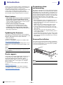
Recessed Installation
If you want to recess the front panel surface of the device
from the front edge of the rack, you can adjust the position
of the rack mount brackets to recess the device by 50mm,
as shown in the illustration below.
NOTE
When updating this product's Dante module firmware, make sure
you also update the Dante module firmware contained in other
connected devices.
NOTE
When you install the brackets, use the same screws that you just
removed.
50 mm

Device features
-
9
-
Owner’s Manual
Tio1608-D
English
Device features
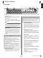
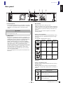
Front panel
1 [INPUT] jacks 1–16
Combination jacks that support both XLR and TRS
phone connectors. Use these jacks to connect mics
and instruments.
Nominal input level is -62 dBu to +10 dBu.
When connecting a cable that uses an XLR plug, make
sure you supply +48 V phantom power to any devices
that require it.
2 [+48V] indicators
These indicators light when +48 V phantom power is
turned on for the corresponding input channels. You
can use a compatible mixing console or other device
to turn phantom power on and off If the [+48V
MASTER] switch is turned off, no phantom power will
be supplied even if phantom power is turned on for
individual channels (although the +48V indicators will
still flash).
3 [OUTPUT +4dBu] jacks 1–8
These XLR-3-32 type balanced connectors deliver
analog output from the unit’s corresponding output
channels. Nominal output level is +4 dBu.
4 [STATUS INPUT] indicator
This indicator indicates the status of the signal being
input to the analog input jacks.
If the signal input to any channel reaches or exceeds
-34 dBFS, the indicator lights in green; if the signal
reaches or exceeds -3 dBFS, the indicator lights in red.
The indicator flashes in red if the input is muted, if the
system clock is being synced, or if there is a system
error.
5 [STATUS OUTPUT] indicator
If the signal level of any analog output jack reaches or
exceeds -34 dBFS, this indicator lights in green.
The indicator flashes in red if the output is muted, if
the system clock is being synced, or if there is a system
error.
6 [UNIT ID] switch
Determines the unit's identifier (i.e., unit ID) when
using Quick Config. When using multiple units, set a
unique ID (1–3) to each unit.
When not using Quick Config, this switch and the DIP
switches on the rear of the unit determine the ID.
(page 11)
Turn the unit off before changing the [UNIT ID] switch
position. If you move the switch while the unit is
turned on, the new switch position is not applied.
See "Connection methods" (page 13) for
information about Quick Config.
7 [QUICK CONFIG] switch
Turns Quick Config on and off.
When not using Quick Config, this switch and the DIP
switches on the rear of the unit determine the ID.
(page 11-12)
Turn the unit off before changing the [QUICK
CONFIG] switch position. If you move the switch
while the unit is turned on, the new switch position is
not applied.
See "Connection methods" (page 13) for
information about Quick Config.
ղձ մյնշոչպջռճ
NOTE
The PAD will be switched on or off internally when the analog
gain of the internal head amp is adjusted between +17dB and
+18dB. When using phantom power, noise may be generated
if there is a difference in the impedance between the hot and
cold of the device connected to an input jack.
Caution
• Make sure that phantom power is turned off unless it is
needed.
• When turning on phantom power, make sure that no
equipment other than phantom-powered devices such
condenser microphones are connected to the corresponding
[INPUT] jacks. Supplying phantom power to a device that
does not require it can damage the device.
• Do not connect or disconnect a device while phantom power
is being supplied to it. Doing so can damage the connected
device and the unit itself.
• To prevent damage to speakers, make sure that power
amplifiers and powered speakers are turned off when turning
phantom power on or off. We also recommend setting all
digital mixing console output controls to their minimum
settings when turning phantom power on or off. Sudden high-
volume sound caused by turning phantom power on or off
could damage equipment and hearing.
NOTICE
If this product's balanced outputs are connected to an
unbalanced audio source, a difference in ground potential may
result that could cause a malfunction. Make sure each device
has the same ground potential. The cable used to connect an
unbalanced device should be pin 1: ground, pin 3: cold.

Device features
-
10
-
Owner’s Manual
Tio1608-D
8 [SYSTEM] indicators
Indicate the status of the Tio1608-D.
During normal operation, the green indicator is lit
and the red indicator is off. When the unit is turned
on, if the green indicator is off and the red indicator is
lit or is flashing, an error has occurred.
9 [SYNC] indicators
Indicate the status of the unit's internal Dante clock
sync.
When the green indicator is lit, the unit is the clock
slave, and the clock is in sync. When the green
indicator is flashing, the unit is the clock master. When
the unit is turned on, the green indicator should either
light or flash; if the indicator is off, an error has
occurred.
0 [+48V MASTER] switch
Turns the unit's +48 V phantom power on and off. If
the [+48V MASTER] switch is off, no phantom power
is supplied to the input jacks even if phantom power
is turned on for individual inputs. In this case, the
+48V indicators for individual inputs will still light,
even though no phantom power will be supplied.
You can change the switch position while the unit is
turned on.
a Power indicator
Indicates whether the unit is turned on or off.
b Power switch
Turns the unit on and off.
NOTICE
Rapidly turning the unit on and off in succession can cause it to
malfunction. After turning the unit off, wait for about 6 seconds
before turning it on again.

Device features
-
11
-
Owner’s Manual
Tio1608-D
English
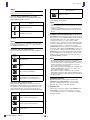
Rear panel
1 AC IN connector
Connect the included power cord. When connecting
to a power outlet, first connect the power cord to the
unit, then connect the power cord to the power
outlet.
2 [FAN] switch
Allows you to set the unit's internal cooling fan to run
at high or low speed. The switch is set at the factory to
[LOW], but as long as the unit is operated within the
specified ambient temperature range either the
[LOW] or [HIGH] setting can be used. The [HIGH]
setting is recommended if the ambient temperature is
high, if the unit is in direct sunlight (even if the
ambient temperature is within the specified operating
range), and in any situation in which fan noise is not
a problem. When mounting three or more units
without leaving space between each unit, set each
unit's fan speed to HIGH.
You can change the switch position while the unit is
turned on.
3 DIP switches
Determines the unit's start up mode.
Make sure that the unit is turned off before adjusting
the DIP switches. If you adjust the switches while the
unit is turned on, the new switch positions are not
applied.
The following information explains how the DIP
switch positions.
• Switch 1 and 2 (unit ID)
These DIP switches, along with the [UNIT ID] switch,
determine the unit's UNIT ID when Quick Config is
not used.
The UNIT ID is determined as follows.
When Quick Config is used, these switches are
disabled.
• Switch 3 (initialize mode)
This DIP switch is used to reset the unit to its factory
default settings.
After the unit is reset, it starts up using the system
mode that corresponds to the position of switches 7
and 8.
ձղճյնմ
Caution
Make sure the unit is turned off before connecting or
disconnecting the power cord.
Switch
position
[UNIT ID]
switch = 1
[UNIT ID]
switch = 2
[UNIT ID]
switch = 3
01 02 03
04 05 06
07 08 09
0A 0B 0C
Switch
position
Initialize mode
Initialize mode is off (unit will not be reset
when it is turned on)
Initialize mode is on (unit will be reset
when it is turned on)
1 2
1 2
1
2
1
2
3
3

Device features
-
12
-
Owner’s Manual
Tio1608-D
• Switch 4 (Dante SECONDARY port mode)
This switch determines the operating mode of the
[SECONDARY] Dante connector.
When Quick Config is used, these switches are
disabled.
• Switches 5 and 6 (IP address mode)
These switches determine how the unit's IP address is
set.
• Switches 7 and 8 (start up mode)
These switches determine how the unit starts up
during start up mode. When set to "refresh" mode,
the settings of the mixer are applied when the unit
starts up. When set to "resume" mode, the unit
returns to the same state as the last time it was used.
When Quick Config is used, the "normal operation"
mode settings are disabled.
4 [PRIMARY] and [SECONDARY] Dante connectors
etherCON CAT5 connector that connects the unit to a
Dante device, such as a NY64-D digital audio interface
card. When DIP switch 4 is set to the daisy-chain
connection position (i.e., up position), signals
received on one connector are sent out via the other
connector. When DIP switch 4 is set to the redundant
connection position (i.e., down position), the
[SECONDARY] connector functions as a backup and
carries the same signals as the [PRIMARY] connector. If
for some reason signals cannot be carried over the
[PRIMARY] connector (for example, because the cable
becomes damaged or disconnected, or because the
network switch malfunctions), the unit switches to
the [SECONDARY] connector.
5 [LINK/ACT] indicators
Indicate the status of the signals carried by the
[PRIMARY] and [SECONDARY] connectors. If an
indicator is flashing quickly, the corresponding
Ethernet cable is not connected properly.
6 [1G] indicators
Indicate the connection status of the PRIMARY and
SECONDARY connectors. If an indicator is lit, the
corresponding connector is connected to a Gigabit
Ethernet network.
NOTE
If switches 7 and 8 are set to the "update mode" or "diagnostic
mode" positions, the unit will not be reset.
Switch
position
[SECONDARY] connector operating
mode
Daisy chain connection
Redundant connection
NOTE
When the Switch 4 is set to "Redundant connection", the
head amp control function (page 14) is only available via
the [PRIMARY] Dante connector.
Switch
position
IP address mode
Auto (link local)
DHCP
Static IP Auto (192.168.0.ID)
Static IP Manual
The IP address is specified from an
external device such as R Remote V3.
Switch
position
Start up mode
Refresh mode (normal operation)
Resume mode (normal operation)
Update mode
4
4
5 6
5
6
5 6
5 6
7
8
7 8
7
8
Diagnostic mode
NOTE
• Update mode and diagnostic mode are used when
performing maintenance on the unit. Normally you will not
use these modes.
• Update mode and diagnostic mode can be enabled even
when using Quick Config. Normally you will not use these
modes.
NOTE
• To avoid electromagnetic interference, use shielded
twisted-pair (STP) cables that are rated at CAT5e or higher.
Use conductive tape or comparable means to make sure
that the metal parts of the cable plugs are electrically
connected to the STP cable shield.
• We recommend using RJ-45 plugs that are compatible with
Neutrik etherCON CAT5 connectors. You can also use
cables with standard RJ-45 plugs.
• The maximum length of cable that can be used varies
depending on the type of cable. When using CAT5e cables,
data can be sent between devices that are connected by up
to 100 m of cable.
Switch
position
Start up mode
7 8

Connection methods
-
13
-
Owner’s Manual
Tio1608-D
English
Connection methods
This section explains the different methods for connecting
the Tio1608-D to other Dante devices.
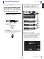
Quick Config (automatic setup)
When connecting the unit to a TF series mixing console,
Quick Config makes it easy to set up the unit automatically.
It allows you to connect up to three Tio1608-D units to one
TF series mixing console, and configures Dante network
settings and audio signal settings in one operation.
Tio1608-D procedure
1. With all the units turned off, set the DIP switches on
the rear panel to the up position.
2. Set the [QUICK CONFIG] switch on the front panel
to the [ON] position.
3. Set the [UNIT ID] switch on the front panel to the
desired position.
If you are using multiple Tio1608-D units, make sure
each unit has a unique UNIT ID setting.
4. Use Ethernet cables to connect the Tio1608-D to the
NY64-D card (installed in the TF series mixing
console) or to other Tio1608-D units in a daisy-
chain configuration, as shown below.
When using Quick Config, the units will operate the same
whether you connect the Ethernet cables to the [PRIMARY] or
[SECONDARY] Dante connector.
When connecting 3 units
5. Turn each device on.
TF series mixing console procedure
6. Display the console's SYSTEM SETUP SLOT SETUP
screen, and confirm that Quick Config is enabled.
Now the TF series mixing console can recognize the
Tio1608-D units, and all Dante settings and input and output
patching settings will be configured automatically.
When the Quick Config button is displayed in white, Quick
Config is enabled. If the button is grayed out, click it. If you
cannot enable Quick Config, return to step
1 and confirm that
the Tio1608-D is configured properly.
NOTE
An NY64-D audio interface card (sold separately) is required to
connect a Tio1608-D to a TF series mixing console.
TF Series (NY64-D)
Tio1608-D UNIT ID=1
Tio1608-D UNIT ID=2
Tio1608-D UNIT ID=3
[PRIMARY] or
[SECONDARY]
connector
[PRIMARY]
connector
[PRIMARY]
connector
[SECONDARY]
connector
[PRIMARY] or
[SECONDARY]
connector
[SECONDARY]
connector

Connection methods
-
14
-
Owner’s Manual
Tio1608-D
7. To assign the Tio1608-D inputs to the TF series
mixing console, set the input select on the console's
INPUT screen to "SLOT".
8. Adjust the input gain and other settings as
necessary.
Quick config is now complete.
Settings configured by Quick Config
Quick Config applies the following settings.
• Dante settings
• Patching
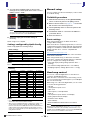
Manual setup
You can configure your devices manually if you do not want
to use Quick Config.
Tio1608-D procedure
1. With the unit turned off, set the [QUICK CONFIG]
switch on the front panel to the [OFF] position.
2. Refer to the information on page 11 - 12 and set the
DIP switches to the desired positions.
3. Set the [UNIT ID] switch on the front panel to the
desired position.
4. Use Ethernet cables to connect the Tio1608-D to
your Dante device.
5. Turn each device on.
Dante settings
When using manual setup, use Dante Controller to
configure Dante settings.
Dante Controller is a computer program that you can use to
configure Dante network settings and audio signal patching
settings. It is available for download at the website below.
(Dante Controller v3.2.1 or later is compatible with
Tio1608-D.)
http://www.yamahaproaudio.com/
For information about Dante Controller, refer to the Dante
Controller documentation.
When using manual setup, you will need to use Dante
Controller to configure the following settings at a minimum.
(You can configure other settings as desired.)
• Input and output patching settings (Network View
Routing)
• Clock master settings (Network View Clock Status)
• Sampling frequency settings (Device View Config)
Head amp control
You can use a Yamaha digital mixer or other device to
control the Tio1608-D head amp.
When the unit is connected to a TF series mixing console,
you can control the unit's head amp just as you would adjust
the console's head amp.
When using a CL or QL series digital mixer, you can control
or use the following parameters.
•HA gain
• +48 V phantom power on/off
• HPF on/off
• HPF frequency cutoff adjustment
• Mute off
• +48 V phantom power master on/off display
• Analog input level meter display
• Firmware version display
• Device identify
• Dante SYSTEM and SYNC indicator information
NOTE
You can use the menu in the console's INPUT screen to switch
the inputs selected for the current FADER BANK.
Word clock 48 kHz (slave), no pull up/down
Latency 0.5 ms
Encoding 24-bit PCM
SECONDARY port mode Daisy chain
Patching Refer to the table below
IP address Previous setting is used
NOTE
Quick Config does not configure analog input parameters.
Tio input TF input TF output Tio output
#1 ID 1, Input 1 Channel 1 AUX 1 ID 1, Output 1
ID 1, Input 2 Channel 2 : :
::AUX 6 ID 1, Output 6
ID 1, Input 16 Channel 16 Stereo L ID 1, Output 7
Stereo R ID 1, Output 8
#2 ID 2, Input 1 Channel 17 AUX 7 ID 2, Output 1
ID 2, Input 2 Channel 18 : :
::
AUX 12 ID 2, Output 6
ID 2, Input 16 Channel 32 Stereo L ID 2, Output 7
Stereo R ID 2, Output 8
#3 ID 3, Input 1 Channel 33 AUX 13 ID 3, Output 1
ID 3, Input 2 Channel 34 : :
::AUX 18 ID 3, Output 6
ID 3, Input 8 Channel 40 AUX 19 ID 3, Output 7
AUX 20 ID 3, Output 8
NOTE
• Even if only UNIT ID 2 or 3 is used, channels are patched as
shown above based on the UNIT ID number.
• After you have used Quick Config to configure the settings, you
can use Dante Controller to change the individual settings.
However, each time the Tio1608-D is turned on, Dante Controller
settings will be replaced by the Quick Config settings. For this
reason, we recommend that you turn Quick Config off if you are
using Dante Controller.
NOTE
When the Dante SECONDARY port mode (page 12) is set to
"Redundant connection", the head amp control function is only
available via the [PRIMARY] Dante connector. The [SECONDARY]
Dante connector is not available for this function.

Troubleshooting
-
15
-
Owner’s Manual
Tio1608-D
English
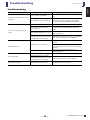
Troubleshooting
Troubleshooting
Issue Cause Solution
No power, power indicator does
not light
Power cord not connected.
Make sure the power cord is connected (page
11).
The [POWER] switch is turned off.
Set the [POWER] switch to the "on" position. If
you still cannot resolve the problem, please
contact your nearest Yamaha representative.
Unit is not receiving an input
signal
Cables not connected properly. Make sure all cables are connected properly.
Source device is not sending a
signal to the unit.
Output a signal from the source device and
confirm that the [STATUS INPUT] indicators
light.
Internal head amp gain is too low.
Adjust the internal head amp gain to an
appropriate level.
DIP switches are set to "refresh"
mode but device that controls the
Tio1608-D has not started up.
Start the device that will control the Tio1608-D
and send the settings to the Tio1608-D.
Input level too low
Condenser mic is connected.
Set the [+48V MASTER] switch to the "on"
position.
Use the device that controls the Tio1608-D to
turn on phantom power for the corresponding
channel.
Internal head amp gain is too low.
Adjust the internal head amp gain to an
appropriate level.
No sound heard
Cables not connected properly. Make sure all cables are connected properly.
DIP switches are set to "refresh"
mode but device that controls the
Tio1608-D has not started up.
Start the device that will control the Tio1608-D
and send the settings to the Tio1608-D.
[UNIT ID] switch or DIP switch
settings not applied
You changed the switch positions
while the unit was turned on.
Make sure the unit is turned off before
changing the switch positions.

How to read the indicators
-
16
-
Owner’s Manual
Tio1608-D
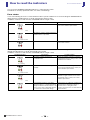
How to read the indicators
You can use the [SYSTEM] and [SYNC] indicators to confirm the unit's status.
The indicators can relay operational status, error status, and warnings.
Error status
If one of the following errors has occurred, the device will not operate. Until the error is resolved, the green SYSTEM indicator
will be turned off, and all indicators for all I/O channels will continue to flash.
In addition, certain errors will cause the red SYSTEM indicator to light or flash.
The following errors affect the settings or the hardware. However, the device will still be usable. The green SYSTEM indicator
will light, and all indicators for all I/O channels will work normally.
In addition, certain errors will cause the red SYSTEM indicator to light or flash.
[SYSTEM] Indicators Description Possible Solution
Off Flashes 2 times
Internal Dante error has occurred. The unit is malfunctioning. Please contact
your nearest Yamaha representative.
Off Flashes 3 times
MAC address setting is damaged and Dante
communication is not possible.
Off Lit
Duplicate UNIT ID was found. Make sure each UNIT ID is only used once
on the Dante network.
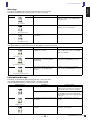
[SYSTEM] Indicators Description Possible Solution
Lit Flashing
The number of Dante transmit flows
exceeded the limit.
Reduce the number of flows by, for example,
using Dante Controller to change some of the
transmit flows to multicast.
Lit Flashes 2 times
Error occurred when communicating with the
head amp.
Turn the unit off and then on again. If this does
not resolve the problem, please contact your
nearest Yamaha representative.
Lit Flashes 3 times
Internal memory has been corrupted. If using [RESUME] mode, turn the unit off
and then on again. If this does not resolve
the problem, please contact your nearest
Yamaha epresentative.
Lit Lit
You changed the positions of the device
setting DIP switches, or changed the Dante
settings from Dante Controller. Therefore, the
positions of the device setting DIP switches
do not match the actual Dante settings.
If the Device Lock setting was enabled from
Dante Controller, disable the setting, or
check the device setting DIP switch
positions, and set them to accommodate the
current situation.

How to read the indicators
-
17
-
Owner’s Manual
Tio1608-D
English
Warnings
The indicators will light and/or flash as shown until the cause is resolved.
If the green [SYNC] indicator is unlit, the unit’s clock is unconfirmed.
If the green indicator is flashing, the unit is the clock master.
If the green indicator is lit, the unit is the clock slave and the clock is synchronized.
Information Message
The indicators will remain lit and/or flashing cyclically to report the status.
If the orange [SYNC] indicator is unlit, the unit is operating normally.
If the green [SYNC] indicator is unlit, the unit's clock is unconfirmed.
[SYNC] Indicators Description Possible Solution
Off Flashing
Clock settings are incorrect. Check the clock master and sampling
frequency settings of the Tio1608-D and
Dante Controller.
Off Flashes 2 times
Unit not connected to Dante network. Make sure the cables are not damaged and
that they are connected properly.
Off Flashes 3 times
Cable wiring is wrong; cannot find other
Dante devices.
Check the wiring of the Ethernet cables.
[SYNC] Indicators Description Possible Solution
Lit or flashing Lit
Device that is not Gigabit Ethernet
compatible is connected.
To use Dante to send and receive digital
audio, make sure your devices are Gigabit
Ethernet compatible.
Lit or flashing Flashing
When using a redundancy network,
[SECONDARY] connector is sending/
receiving audio.
Check the connections of the network
connected to the [PRIMARY] connector.
Lit or flashing Flashes 2 times
When using a redundancy network, error
was detected on the [SECONDARY]
connector.
Check the connections of the network
connected to the [SECONDARY] connector.
[SYNC] Indicators Description Possible Solution
Off Lit
Synchronizing on a Dante network. Please wait until started has completed or
until the unit has finished synchronization. It
may take up to 45 seconds for completion.
Waiting to receive setting data. If START UP MODE is set to REFRESH on
the Tio1608-D unit, the input/output will be
muted until the unit receives setting data after
it starts up.
Flashing Off
The unit is functioning correctly as the word
clock master.
The unit is operating as the word clock
master.
Lit Off
The unit is functioning correctly as the word
clock slave.
The unit is operating as the clock slave and
the clock is synchronized.

-
18
-
Bedienungsanleitung
Tio1608-D

Specifications
Owner’s Manual
Tio1608-D
-
119
-
EnglishDeutschFrançais
EspañolPortuguêsItaliano
Русский
Specifications
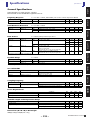
General Specifications
Output impedance of signal generator: 150ohms
Measured with another Tio1608-D through Dante network.
Frequency Response Fs = 44.1kHz or 48kHz, 20Hz-20kHz, refer to the nominal output level @1kHz
Total Harmonic Distortion Fs = 44.1kHz or 48kHz
* Total Harmonic Distortion is measured with a -18dB/octave filter @80kHz
Hum & Noise Fs = 48kHz, EIN: Equivalent Input Noise
* Hum & Noise are measured with A-weighting filter.
Dynamic Range Fs = 48kHz
* Dynamic Range are measured with A-weighting filter.
Crosstalk@1kHz
* Crosstalk is measured with a -30dB/octave filter @22kHz
Sampling Frequency
Power Requirements
AC Cable Length and Temperature Range
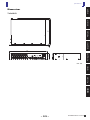
Dimensions (W x H x D) & Net weight
480(W) x 88(H) x 364(D) mm, 5.7kg
Input
Output RL Conditions Min. Typ. Max. Unit
INPUT1-16 OUTPUT 1-8 600Ω GAIN: +66dB. -1.5 0.0 0.5 dB
Input
Output RL Conditions Min. Typ. Max. Unit
INPUT1-16 OUTPUT 1-8 600Ω +4dBu@20Hz-20kHz, GAIN: +66dB. 0.1 %
600Ω +4dBu@20Hz-20kHz, GAIN: -6dB. 0.05 %
Input
Output RL Conditions Min. Typ. Max. Unit
INPUT1-16 OUTPUT 1-8 600Ω Rs=150Ω, GAIN: +66dB. -128
EIN
dBu
-62 dBu
600Ω Rs=150Ω, GAIN: -6dB. -84 -80 dBu
all Inputs OUTPUT 1-8 600Ω Rs=150Ω, GAINs: -6dB
Master fader at nominal level and all INPUT 1-16 in
faders at nominal level.
Measured with TF5 (or TF3,TF1) through Dante.
-70 dBu
- OUTPUT 1-8 600Ω Residual output noise, STEREO master off.
Measured with TF5 (or TF3,TF1) through Dante.
-88 dBu
Input
Output RL Conditions Min. Typ. Max. Unit
INPUT1-16 OUTPUT 1-8 600Ω AD + DA, GAIN: -6dB. 108 dB
- OUTPUT 1-8 600Ω DA Converter 112 dB
from/to
to/from Conditions Min. Typ. Max. Unit
INPUT n INPUT (n-1) or (n+1) INPUT1-16
adjacent inputs, GAIN: -6dB.
-100 dB
OUTPUT n OUTPUT (n-1) or (n+1) OUTPUT 1-8, input to output -100 dB
Conditions Min. Typ. Max. Unit
External Clock Frequency Range 44.1kHz / 48kHz -200 +200 ppm
+4.1667%/+0.1%/-0.1%/-4.0% to all of the above -200 +200 ppm
Conditions Min. Typ. Max. Unit
Power Requirements 100-240V 50/60Hz 50 W
Heat Dissipation 100-240V 50/60Hz 43.5 kcal/h
Conditions Min. Typ. Max. Unit
AC Cable Length 2.5 m
Temperature Range Operating temperature range 0 40 °C
Storage temperature range -20 60 °C

Specifications
Owner’s Manual
Tio1608-D
-
120
-
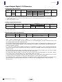
Input Output Digital I/O Character
Analog input characteristics
Analog output characteristics
Digital input/output specifications
* The contents of this manual apply to the latest specifications as of the publishing date. To obtain the latest manual, access
the Yamaha website then download the manual file.
* Der Inhalt dieser Bedienungsanleitung gilt für die neuesten technischen Daten zum Zeitpunkt der Veröffentlichung. Um die
neueste Version der Anleitung zu erhalten, rufen Sie die Website von Yamaha auf und laden Sie dann die Datei mit der
Bedienungsanleitung herunter.
* Le contenu de ce mode d’emploi s’applique aux dernières caractéristiques techniques connues à la date de publication du
manuel. Pour obtenir la version la plus récente du manuel, accédez au site Web de Yamaha puis téléchargez le fichier du
manuel concerné.
* El contenido de este manual se aplica a las últimas especificaciones según la fecha de publicación. Para obtener el último
manual, acceda al sitio web de Yamaha y descargue el archivo del manual.
* O conteúdo deste manual se aplica às especificações mais recentes a partir da data de publicação. Para obter o manual
mais recente, acesse o site da Yamaha e faça o download do arquivo do manual.
* Il contenuto del presente manuale si applica alle ultime specifiche tecniche a partire dalla data di pubblicazione. Per ottenere
la versione più recente del manuale, accedere al sito Web Yamaha e scaricare il file corrispondente.
* В содержании данного руководства приведены последние на момент публикации технические характеристики.
Для получения последней версии руководства посетите веб-сайт корпорации Yamaha и загрузите файл с
руководством.
Input
Terminals
GAIN
Actual Load
Impedance
For Use With
Nominal
Input Level
Connector
balanced /
Unbalanced
Sensitivity
*1
*1. Sensitivity is the lowest level that will produce an output of +4dBu (1.23V) or the nominal output level when the unit is set to maximum gain.
Nominal Max. before clip
INPUT1-16 +66dB 7.5kΩ 50-600Ω Mics
or 600Ω Lines
-82dBu
(61.6μV)
-62dBu
(0.616mV)
-42dBu
(6.16mV)
Combo Jack
(XLR-3-31 type
*2
or
TRS phone
*3
)
*2. 1: GND, 2: HOT, 3: COLD
*3. Tip: HOT, Ring: COLD, Sleeve: GND
Balanced
-6dB -10dBu
(245mV)
+10dBu
(2.45V)
+30dBu
(24.5V)
In these specifications, 0dBu = 0.775Vrms.
+48V DC (phantom power) can be supplied to INPUT XLR type connectors via each individual software controlled switch.
Output Terminals
Actual Sourcez
Impedance
For Use With
Nominal
Output Level
Connector
balanced /
Unbalanced
Nominal Max. before clip
OUTPUT 1-8 75Ω 600Ω Lines +4dBu
(1.23 V)
+24dBu
(12.3 V)
XLR-3-32 type
*1
*1. 1: GND, 2: HOT, 3: COLD
Balanced
In these specifications, 0dBu = 0.775Vrms.
Terminal Format Data length Level Audio Connector
Primary / Secondary Dante 24 or 32bit 1000BASE-T 16ch (Tio1608-D to other devices)
8ch (Other devices to Tio1608-D)
etherCON Cat5e
Sidan laddas ...
Sidan laddas ...
Sidan laddas ...
Sidan laddas ...
-
 1
1
-
 2
2
-
 3
3
-
 4
4
-
 5
5
-
 6
6
-
 7
7
-
 8
8
-
 9
9
-
 10
10
-
 11
11
-
 12
12
-
 13
13
-
 14
14
-
 15
15
-
 16
16
-
 17
17
-
 18
18
-
 19
19
-
 20
20
-
 21
21
-
 22
22
-
 23
23
-
 24
24


Yamaha Tio1608 Bruksanvisning
- Kategori
- Musikutrustning
- Typ
- Bruksanvisning
- Denna manual är också lämplig för
på andra språk
- italiano: Yamaha Tio1608 Manuale del proprietario
- čeština: Yamaha Tio1608 Návod k obsluze
- español: Yamaha Tio1608 El manual del propietario
- Deutsch: Yamaha Tio1608 Bedienungsanleitung
- polski: Yamaha Tio1608 Instrukcja obsługi
- português: Yamaha Tio1608 Manual do proprietário
- français: Yamaha Tio1608 Le manuel du propriétaire
- Türkçe: Yamaha Tio1608 El kitabı
- English: Yamaha Tio1608 Owner's manual
- dansk: Yamaha Tio1608 Brugervejledning
- русский: Yamaha Tio1608 Инструкция по применению
- suomi: Yamaha Tio1608 Omistajan opas
- Nederlands: Yamaha Tio1608 de handleiding
- română: Yamaha Tio1608 Manualul proprietarului