Tunturi E60-R Användarmanual
- Kategori
- Snurrcyklar
- Typ
- Användarmanual
Denna manual är också lämplig för

www�tunturi�com
- Please read this assembly manual carefully prior to assembling this product.
- Lesen Sie sich vor der Montage des Produkts diese Montageanleitung sorgfältig durch.
- Veuillez lire attentivement le présent manuel d’assemblage avant de monter ce produit.
- Lees deze montagehandleiding zorgvuldig voordat u dit product in elkaar gaat zetten.
- Leggere attentamente questo manuale di montaggio prima di montare il prodotto.
- Antes de montar este producto, lea atentamente este manual de montaje.
- Läs den här monteringshandboken noggrant före användning av den här produkten.
- Lue tämä asennusohje huolellisesti ennen tämän tuotteen asennusta.
Attention, Achtung, Attention, Attentie, Attenzione, Atención, Giv akt, Huomio
GB Assembly manual
DE Montageanleitung
FR Manuel d’assemblage
NL Montagehandleiding
IT Manuale di montaggio
ES Manual de montaje
SV Monteringshandbok
SU Asennusohje
E60-R Bike Performance
EN957
Class HB
Made in China
RoHS
2011/65/EU
i
SN:
HOME USE
MAX USER WEIGHT: 135 KGS
300 LBS
INPUT: AC 110 - 220~240V
50-60HZ 2.3 Amp.
SKU: 20TBR60000
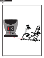
Recumbent bike E60-R
ROUTES
Tunturi Routes
iOS & Android
17 - 20
21 - 25
26 - 30
31 - 35
36 - 40
41 - 45
46 - 50
51 - 54
GET YOUR
USER MANUAL
ONLINE
http://manuals.tunturi.com
WWW
IMPORTANT


3
F20 Bike
A

i
4
F20 Bike
B

100 cm
100 cm
100 cm
100 cm
113: Allen Bolt M8xP1.25x12mm (2pcs)
114: Flat Washer Ø8*Ø16*2L (6pcs)
116: Flat Washer Ø8*Ø19*2L (4pcs)
112: Allen Bolt M8xP1.25x16mm (4pcs)111: Allen Bolt M8xP1.25x35Lmm (2pcs)
110: Allen Bolt M8xP1.25x60mm (4pcs)
Allen Key 5MM (1)
Allen Key 6MM (1)
Screwdriver (1)
Wrench (1)
5
F20 Bike
C
D

113: Allen Bolt M8xP1.25x12mm (2pcs)
114: Flat Washer Ø8*Ø16*2L (6pcs)
116: Flat Washer Ø8*Ø19*2L (4pcs)
112: Allen Bolt M8xP1.25x16mm (4pcs)111: Allen Bolt M8xP1.25x35Lmm (2pcs)
110: Allen Bolt M8xP1.25x60mm (4pcs)
Allen Key 5MM (1)
Allen Key 6MM (1)
Screwdriver (1)
Wrench (1)
6
F20 Bike
D-1

113: Allen Bolt M8xP1.25x12mm (2pcs)
114: Flat Washer Ø8*Ø16*2L (6pcs)
116: Flat Washer Ø8*Ø19*2L (4pcs)
112: Allen Bolt M8xP1.25x16mm (4pcs)111: Allen Bolt M8xP1.25x35Lmm (2pcs)
110: Allen Bolt M8xP1.25x60mm (4pcs)
Allen Key 5MM (1)
Allen Key 6MM (1)
Screwdriver (1)
Wrench (1)
7
F20 Bike
D-2

L
Left hand crank
Make sure to use Left hand pedal
L
Fit the left hand pedal into
the left hand crank.
Firstly turn the pedal axle in
counter-clockwise direction by hand.
Use the wrench to fully
tightnen the pedal.
1.
2.
3.
R
Right hand crank
Make sure to use Right hand pedal
R
Fit the right hand pedal into
the right hand crank.
Firstly turn the pedal axle in
clockwise direction by hand.
Use the wrench to fully
tightnen the pedal.
1.
2.
3.
113: Allen Bolt M8xP1.25x12mm (2pcs)
114: Flat Washer Ø8*Ø16*2L (6pcs)
116: Flat Washer Ø8*Ø19*2L (4pcs)
112: Allen Bolt M8xP1.25x16mm (4pcs)111: Allen Bolt M8xP1.25x35Lmm (2pcs)
110: Allen Bolt M8xP1.25x60mm (4pcs)
Allen Key 5MM (1)
Allen Key 6MM (1)
Screwdriver (1)
Wrench (1)
8
F20 Bike
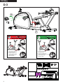
D-3

A
B
C
113: Allen Bolt M8xP1.25x12mm (2pcs)
114: Flat Washer Ø8*Ø16*2L (6pcs)
116: Flat Washer Ø8*Ø19*2L (4pcs)
112: Allen Bolt M8xP1.25x16mm (4pcs)111: Allen Bolt M8xP1.25x35Lmm (2pcs)
110: Allen Bolt M8xP1.25x60mm (4pcs)
Allen Key 5MM (1)
Allen Key 6MM (1)
Screwdriver (1)
Wrench (1)
9
F20 Bike
D-4

A-1
A-1
A-1
A-2
A-2
A-1 A-2
113: Allen Bolt M8xP1.25x12mm (2pcs)
114: Flat Washer Ø8*Ø16*2L (6pcs)
116: Flat Washer Ø8*Ø19*2L (4pcs)
112: Allen Bolt M8xP1.25x16mm (4pcs)111: Allen Bolt M8xP1.25x35Lmm (2pcs)
110: Allen Bolt M8xP1.25x60mm (4pcs)
Allen Key 5MM (1)
Allen Key 6MM (1)
Screwdriver (1)
Wrench (1)
10
F20 Bike
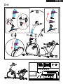
D-5

113: Allen Bolt M8xP1.25x12mm (2pcs)
114: Flat Washer Ø8*Ø16*2L (6pcs)
116: Flat Washer Ø8*Ø19*2L (4pcs)
112: Allen Bolt M8xP1.25x16mm (4pcs)111: Allen Bolt M8xP1.25x35Lmm (2pcs)
110: Allen Bolt M8xP1.25x60mm (4pcs)
Allen Key 5MM (1)
Allen Key 6MM (1)
Screwdriver (1)
Wrench (1)
11
F20 Bike
D-6

113: Allen Bolt M8xP1.25x12mm (2pcs)
114: Flat Washer Ø8*Ø16*2L (6pcs)
116: Flat Washer Ø8*Ø19*2L (4pcs)
112: Allen Bolt M8xP1.25x16mm (4pcs)111: Allen Bolt M8xP1.25x35Lmm (2pcs)
110: Allen Bolt M8xP1.25x60mm (4pcs)
Allen Key 5MM (1)
Allen Key 6MM (1)
Screwdriver (1)
Wrench (1)
AB
12
F20 Bike
D-7

113: Allen Bolt M8xP1.25x12mm (2pcs)
114: Flat Washer Ø8*Ø16*2L (6pcs)
116: Flat Washer Ø8*Ø19*2L (4pcs)
112: Allen Bolt M8xP1.25x16mm (4pcs)111: Allen Bolt M8xP1.25x35Lmm (2pcs)
110: Allen Bolt M8xP1.25x60mm (4pcs)
Allen Key 5MM (1)
Allen Key 6MM (1)
Screwdriver (1)
Wrench (1)
13
F20 Bike
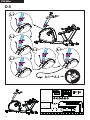
D-8

113: Allen Bolt M8xP1.25x12mm (2pcs)
114: Flat Washer Ø8*Ø16*2L (6pcs)
116: Flat Washer Ø8*Ø19*2L (4pcs)
112: Allen Bolt M8xP1.25x16mm (4pcs)111: Allen Bolt M8xP1.25x35Lmm (2pcs)
110: Allen Bolt M8xP1.25x60mm (4pcs)
Allen Key 5MM (1)
Allen Key 6MM (1)
Screwdriver (1)
Wrench (1)
A B
14
F20 Bike
D-9

113: Allen Bolt M8xP1.25x12mm (2pcs)
114: Flat Washer Ø8*Ø16*2L (6pcs)
116: Flat Washer Ø8*Ø19*2L (4pcs)
112: Allen Bolt M8xP1.25x16mm (4pcs)111: Allen Bolt M8xP1.25x35Lmm (2pcs)
110: Allen Bolt M8xP1.25x60mm (4pcs)
Allen Key 5MM (1)
Allen Key 6MM (1)
Screwdriver (1)
Wrench (1)
A
B
15
F20 Bike
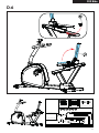
D-10

RESET
OFF
16
F20 Bike
E

17
English
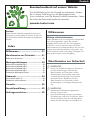
USER MANUAL ON OUR WEBSITE
To reduce the impact on the environment, you will only
find the assembly steps in this manual.
To learn how to use this product, please download the
user manual from:
manuals.tunturi.com
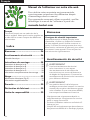
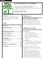
Index
Welcome ����������������������������������������� 17
Safety warnings ������������������������������ 17
Electrical safety �������������������������������������������������� 18
Assembly instructions ��������������������� 18
Description illustration A ����������������������������������� 18
Description illustration B������������������������������������ 18
Description illustration C ����������������������������������� 18
Description illustration D ����������������������������������� 18
Additional assembly information� ��������������������� 19
Use�������������������������������������������������� 19
Power supply (Fig� E) ����������������������������������������� 20
Additional information ��������������������������������������� 20
Warranty ����������������������������������������� 20
Declaration of the manufacturer ���� 20
Disclaimer ��������������������������������������� 20
Welcome
Important Safety Instructions
This Owner’s Manual is an essential part of your
training equipment: reading all instructions in this
manual before you start using this appliance. The
following precautions must always be followed:
Safety warnings
⚠ WARNING
• Read the safety warnings and the
instructions. Failure to follow the safety
warnings and the instructions can cause
personal injury or damage to the equipment.
Keep the safety warnings and the
instructions for future reference.
⚠ WARNING
• Heart rate monitoring systems may be
inaccurate.
• Over exercise may result in serious injury
or death. If you feel faint stop exercising
immediately.
- The equipment is suitable for domestic
use only. The equipment is not suitable for
commercial use.
- Max. usage is limited to 5 hrs a day.
- The use of this equipment by children or
persons with a physical, sensory, mental
or motorial disability, or lack of experience
and knowledge can give cause to hazards.
Persons responsible for their safety must give
explicit instructions or supervise the use of the
equipment.
- Before starting your workout, consult a
physician to check your health.
- If you experience nausea, dizziness or other
abnormal symptoms, immediately stop your
workout and consult a physician.
- To avoid muscular pain and strain, start each
workout by warming up and finish each workout
by cooling down. Remember to stretch at the
end of the workout.
- The equipment is suitable for indoor use only.
The equipment is not suitable for outdoor use.

18
English
- Only use the equipment in environments
with adequate ventilation. Do not use the
equipment in draughty environments in order
not to catch a cold.
- Only use the equipment in environments with
ambient temperatures between 10°C~35°C/
50°F~95°F. Only store the equipment in
environments with ambient temperatures
between 5°C~45°C/ 41°F~113°F.
- Do not use or store the equipment in humid
surroundings. The air humidity must never be
more than 80%.
- Only use the equipment for its intended
purpose. Do not use the equipment for other
purposes than described in the manual.
- Do not use the equipment if any part is
damaged or defective. If a part is damaged or
defective, contact your dealer.
- Keep your hands, feet and other body parts
away from the moving parts.
- Keep your hair away from the moving parts.
- Wear appropriate clothing and shoes.
- Keep clothing, jewellery and other objects away
from the moving parts.
- Make sure that only one person uses the
equipment at a time. The equipment must not
be used by persons weighing more than 135 kg
(300 lbs).
- Do not open equipment without consulting
your dealer.
Electrical safety
(Only for equipment with electric power)
- Before use, always check that the mains voltage
is the same as the voltage on the rating plate of
the equipment.
- Do not use an extension cable.
- Keep the mains cable away from heat, oil and
sharp edges.
- Do not alter or modify the mains cable or the
mains plug.
- Do not use the equipment if the mains cable or
the mains plug is damaged or defective. If the
mains cable or the mains plug is damaged or
defective, contact your dealer.
- Always fully unwind the mains cable.
- Do not run the mains cable underneath the
equipment. Do not run the mains cable
underneath a carpet. Do not place any objects
on the mains cable.
- Make sure that the mains cable does not hang
over the edge of a table.
- Make sure that the mains cable cannot be
caught accidentally or tripped over.
- Do not leave the equipment unattended when
the mains plug is inserted into the wall socket.
- Do not pull the mains cable to remove the
mains plug from the wall socket.
- Remove the mains plug from the wall socket
when the equipment is not in use, before
assembly or disassembly and before cleaning
and maintenance.
Assembly instructions
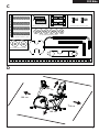
Description illustration A
The illustration shows what the trainer will looks
like after the assembly is completed.
You can use this as a reference during your
assembly, but do follow the assembly steps
always in the correct sequence as showed in the
illustrations.
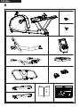
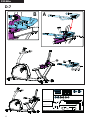
Description illustration B
The illustration shows what components and parts
you should find when un-boxing your product.
‼ NOTE
• Small parts can be hidden/ packed in hollow
spaces in the Styrofoam product protection
• If a part is missing, contact your dealer.
Description illustration C
The illustration shows the hardware kit that comes
with your product.
The hardware kit contains bolts, washers, screws
, nuts etc. and the required tools to properly fit
your trainer.
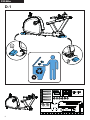
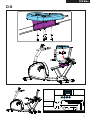
Description illustration D
The illustrations shows you in the correct following
order how to assembly your trainer best.

19
English
‼ NOTE
• Part numbers shown in the assembly steps
are commencing with the spare part drawing
that can be found in the online full version
user manual.
⚠ WARNING
• Assemble the equipment in the given order.
• Carry and move the equipment with at least
two persons.
⚠ CAUTION
• Place the equipment on a firm, level surface.
• Place the equipment on a protective base to
prevent damage to the floor surface.
• Allow at least 100 cm of clearance around
the equipment.
• Refer to the illustrations for the correct
assembly of the equipment.
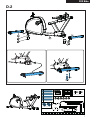
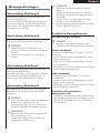
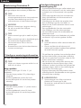
Additional assembly information�
D3 How to fit the pedals correctly�
‼ NOTE
• Right and left side are determined from an
exercising positions perspective.
Right hand pedal
Find the “R” or “L” mark on the pedal axle
- Fit the right hand pedal “R” into the right hand
crank.
- Firstly turn the pedal axle in clockwise direction
by hand.
- Use the wrench to fully tighten the pedal.
Left hand pedal
- Fit the left hand pedal “L” into the left hand
crank.
- Firstly turn the pedal axle in counter-clockwise
direction by hand.
- Use the wrench to fully tighten the pedal.
Additional information to Assembly step
D5
- Establish the wire connection between the
cable coming from the main frame, and the
lower part of the cable pre fitted in the upright
tube.
- Place the upright tube over the main frame
fixing bracket, in where the fixing bolts are pre-
assembled and stay pre-assembled.
( While lowering the upright tube, gently pull
the upper part of the cable up, to avoid the
cable get caught by the connection. )
- The upright tube should automatically find the
centre position, but it is advisable to make the
slightest correction needed to make sure the
position is good.
- The perfect position is when the fixing bolts are
perfectly centred in line with the upright tube
holes.
‼ NOTE
• Avoid the cable connection between these
two parts get pinched.
• By fastening the two bolts (turning in
clockwise direction) on the front side you will
widen the fixing bracket so the upright gets
fixed firmly.
- To fix the upright tube firmly it is needed to
tighten the bolt on the upper side first firmly.
- After fixing the upper bold, you need to fix the
lower bold firmly.
- By fixing the lower bold, the upright tube will
be repositioned slightly resulting that the upper
bold can be fixed a little more, therefore it is
needed to fix the upper bolt again.
- Repeat these steps until both bolts are firmly
fixed to ensure the upright tube fixation well.
‼ NOTE
• Save the tools provided with this product,
after you completed the product assembly,
for future service purposes.
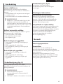
Use
Adjusting the support feet
The equipment is equipped with 5 support feet. If
the equipment is not stable, the support feet can
be adjusted.
- Turn the support feet as required to put the
equipment in a stable position.
- Tighten the locknuts to lock the support feet.
‼ NOTE
• The machine is the most stable when all
support feet are turned fully in. Therefore
start to level the machine by turning all
support feet fully in, before turning out the
required support feet to stable the machine.

20
English
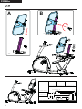
Adjusting the horizontal seat position
The horizontal seat position can be adjusted by
setting the seat to the required position.
- Loosen the quick release lever under the seat.
- Slide the seat forward or backward as desired.
- Tighten the quick release lever.
Adjusting the backrest inclination
- Loosen the backrest inclination adjustment
knob.
- Move the backrest to the required position.
- Tighten the backrest inclination adjustment
knob.
Adjusting the backrest height
- Loosen the backrest height adjustment knob.
- Move the backrest to the required position.
- Tighten the backrest adjustment knob.
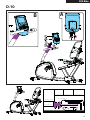
Power supply (Fig� E)
The trainer is powered by an external power
supply. Refer to the illustration to locate the
trainer power input.
‼ NOTE
• Connect the power supply with the trainer
before connecting it to the wall outlet.
• Always remove power cord when machine is
not in use.
Master power switch (fig� E)
The equipment is equipped with a master power
switch to shut down the equipment completely.
Additional information
Packaging disposal
Government guidelines ask that we reduce the
amount of waste material disposed of in land fill
sites. We therefore ask that you dispose of all
packaging waste responsibly at public recycling
centres.
End of life disposal
We at Tunturi hope you enjoy many years of
enjoyable use from your fitness trainer. However,
a time will come when your fitness trainer will
come to the end of its useful life. Under ‘European
WEEE Legislation you are responsible for the
appropriate disposal of your fitness trainer to a
recognised public collection facility.
Warranty
Tunturi purchaser‘s warranty
Warranty terms
The consumer is entitled to the applicable legal
rights stated in the national legislation concerning
the commerce of consumer goods. This warranty
does not restrict these rights. The Purchaser’s
Warranty is only valid if the item is used in an
environment approved by Tunturi New Fitness BV
for that particular equipment. The product-specific
approved environment is stated in the Owner’s
Manual provided with your equipment.
Declaration of the manufac-
turer
Tunturi New Fitness BV declares that the product
is in conformity with the following standards and
directives: EN 957 (HB), 2014/30/EU.
The product therefore carries the CE label.
04-2020
Tunturi New Fitness BV
Purmerweg 1
1311 XE Almere
The Netherlands
Disclaimer
© 2020 Tunturi New Fitness BV
All rights reserved.
- The product and the manual are subject to
change.
- Specifications can be changed without further
notice.
- Check our website for the latest user manual
version.
Sidan laddas...
Sidan laddas...
Sidan laddas...
Sidan laddas...
Sidan laddas...
Sidan laddas...
Sidan laddas...
Sidan laddas...
Sidan laddas...
Sidan laddas...
Sidan laddas...
Sidan laddas...
Sidan laddas...
Sidan laddas...
Sidan laddas...
Sidan laddas...
Sidan laddas...
Sidan laddas...
Sidan laddas...
Sidan laddas...
Sidan laddas...
Sidan laddas...
Sidan laddas...
Sidan laddas...
Sidan laddas...
Sidan laddas...
Sidan laddas...
Sidan laddas...
Sidan laddas...
Sidan laddas...
Sidan laddas...
Sidan laddas...
Sidan laddas...
Sidan laddas...
Sidan laddas...
Sidan laddas...
-
 1
1
-
 2
2
-
 3
3
-
 4
4
-
 5
5
-
 6
6
-
 7
7
-
 8
8
-
 9
9
-
 10
10
-
 11
11
-
 12
12
-
 13
13
-
 14
14
-
 15
15
-
 16
16
-
 17
17
-
 18
18
-
 19
19
-
 20
20
-
 21
21
-
 22
22
-
 23
23
-
 24
24
-
 25
25
-
 26
26
-
 27
27
-
 28
28
-
 29
29
-
 30
30
-
 31
31
-
 32
32
-
 33
33
-
 34
34
-
 35
35
-
 36
36
-
 37
37
-
 38
38
-
 39
39
-
 40
40
-
 41
41
-
 42
42
-
 43
43
-
 44
44
-
 45
45
-
 46
46
-
 47
47
-
 48
48
-
 49
49
-
 50
50
-
 51
51
-
 52
52
-
 53
53
-
 54
54
-
 55
55
-
 56
56


Tunturi E60-R Användarmanual
- Kategori
- Snurrcyklar
- Typ
- Användarmanual
- Denna manual är också lämplig för
på andra språk
- italiano: Tunturi E60-R Manuale utente
- español: Tunturi E60-R Manual de usuario
- Deutsch: Tunturi E60-R Benutzerhandbuch
- français: Tunturi E60-R Manuel utilisateur
- English: Tunturi E60-R User manual
- suomi: Tunturi E60-R Ohjekirja
- Nederlands: Tunturi E60-R Handleiding