Simplicity 13H132-0123-B8 Användarmanual
- Kategori
- Tillbehör till motorfordon
- Typ
- Användarmanual

Not for
Reproduction
Copyright © Briggs & Stratton Corporation
Milwaukee, WI, USA. All rights reserved.
80084929
Revision: A


Not for
Reproduction
3
9
10
11
12
13
14
15
16
17
18
19

Not for
Reproduction
4 VanguardEngines.com
Copyright © Briggs & Stratton Corporation, Milwaukee, WI, USA. All rights reserved.
This manual contains safety information to make you aware of the hazards and risks
associated with engines and how to avoid them. It also contains instructions for the
proper use and care of the engine. Because Briggs & Stratton Corporation does not
necessarily know what equipment this engine will power, it is important that you read
and understand these instructions and the instructions for the equipment.Save these
original instructions for future reference.
Note:The figures and illustrations in this manual are provided for reference only and
may differ from your specific model. Contact your dealer if you have questions.
For replacement parts or technical assistance, record below the engine model, type,
and code numbers along with the date of purchase. These numbers are located on your
engine (see theFeatures and Controlssection).
Date of Purchase
Engine Model - Type - Trim
Engine Serial Number
European Office Contact
Information
For questions regarding European emissions, please contact our European office at:
Max-Born-Straße 2, 68519 Viernheim, Germany.
European Union (EU) Stage
V (5): Carbon Dioxide (CO
2
)
Values
Carbon dioxide values of Briggs & Stratton EU Type-Approval Certificate engines can be
found by entering CO2 into the search window on BriggsandStratton.com.
Recycling Information
Recycle all packaging, used oil, and batteries according to
applicable government regulations.
Operator Safety
Safety Alert Symbol and Signal Words
The safety alert symbol ( ) is used to identify safety information about hazards that
can result in personal injury. A signal word (DANGER, WARNING, or CAUTION) is used
with the alert symbol to indicate the likelihood and the potential severity of injury. In
addition, a hazard symbol may be used to represent the type of hazard.
DANGERindicates a hazard which, if not avoided,will result in death or
serious injury.
WARNINGindicates a hazard which, if not avoided,could result in death or
serious injury.
CAUTIONindicates a hazard which, if not avoided,could result in minor or
moderate injury.
NOTICEindicates a situation thatcould result in damage to the product.
Hazard Symbols and Meanings
Safety information about
hazards that can result in
personal injury.
Read and understand the
Operator's Manual before
operating or servicing the
unit.
Fire hazard Explosion hazard
Shock hazard Toxic fume hazard
Hot surface hazard Noise hazard - Ear protection
recommended for extended
use.
Thrown object hazard -
Wear eye protection.
Explosion hazard
Frostbite hazard Kickback hazard
Amputation hazard -
moving parts
Chemical hazard
Thermal heat hazard Corrosive
Safety Messages
WARNING
Briggs & Stratton® Engines are not designed for and are not to be used to power:
fun-karts; go-karts; children's, recreational, or sport all-terrain vehicles (ATVs);
motorbikes; hovercraft; aircraft products; or vehicles used in competitive events not
sanctioned by Briggs & Stratton. For information about competitive racing products,
see www.briggsracing.com. For use with utility and side-by-side ATVs, please contact
Briggs & Stratton Power Application Center, 1-866-927-3349. Improper engine
application may result in serious injury or death.
WARNING
Fuel and its vapors are extremely flammable and explosive.
Fire or explosion can cause severe burns or death.
When Adding Fuel
• Turn engine off and let engine cool at least 2 minutes before removing the fuel
cap.
• Fill fuel tank outdoors or in well-ventilated area.
• Do not overfill fuel tank. To allow for expansion of the fuel, do not fill above the
bottom of the fuel tank neck.
• Keep fuel away from sparks, open flames, pilot lights, heat, and other ignition
sources.
• Check fuel lines, tank, cap, and fittings frequently for cracks or leaks. Replace if
necessary.
• If fuel spills, wait until it evaporates before starting engine.
When Starting Engine
• Make sure that spark plug, muffler, fuel cap and air cleaner (if equipped) are in
place and secured.
• Do not crank engine with spark plug removed.
• If engine floods, set choke (if equipped) to OPEN / RUN position, move throttle (if
equipped) to FAST position and crank until engine starts.
When Operating Equipment
• Do not tip engine or equipment at angle which causes fuel to spill.

Not for
Reproduction
5
• Do not choke the carburetor to stop engine.
• Never start or run the engine with the air cleaner assembly (if equipped) or the air
filter (if equipped) removed.
When Changing Oil
• If you drain the oil from the top oil fill tube, the fuel tank must be empty or fuel can
leak out and result in a fire or explosion.
When Tipping Unit for Maintenance
• When performing maintenance that requires the unit to be tipped, the fuel tank, if
mounted on the engine, must be empty or fuel can leak out and result in a fire or
explosion.
When Transporting Equipment
• Transport with fuel tank EMPTY or with fuel shut-off valve in the CLOSED
position.
When Storing Fuel Or Equipment With Fuel In Tank
• Store away from furnaces, stoves, water heaters or other appliances that have
pilot lights or other ignition sources because they can ignite fuel vapors.
WARNING
Starting engine creates sparking.
Sparking can ignite nearby flammable gases.
Explosion and fire could result.
• If there is natural or LP gas leakage in area, do not start engine.
• Do not use pressurized starting fluids because vapors are flammable.
WARNING
POISONOUS GAS HAZARD. Engine exhaust contains carbon monoxide, a
poisonous gas that could kill you in minutes. You CANNOT see it, smell it, or
taste it. Even if you do not smell exhaust fumes, you could still be exposed
to carbon monoxide gas. If you start to feel sick, dizzy, or weak while using
this product, get to fresh air RIGHT AWAY. See a doctor. You may have carbon
monoxide poisoning.
• Operate this product ONLY outside far away from windows, doors and vents to
reduce the risk of carbon monoxide gas from accumulating and potentially being
drawn towards occupied spaces.
• Install battery-operated carbon monoxide alarms or plug-in carbon monoxide
alarms with battery back-up according to the manufacturer's instructions. Smoke
alarms cannot detect carbon monoxide gas.
• DO NOT run this product inside homes, garages, basements, crawlspaces,
sheds, or other partially-enclosed spaces even if using fans or opening doors and
windows for ventilation. Carbon monoxide can quickly build up in these spaces
and can linger for hours, even after this product has shut off.
• ALWAYS place this product downwind and point the engine exhaust away from
occupied spaces.
WARNING
Rapid retraction of starter cord (kickback) will pull hand and arm toward engine
faster than you can let go.
Broken bones, fractures, bruises or sprains could result.
• When starting engine, pull the starter cord slowly until resistance is felt and then
pull rapidly to avoid kickback.
• Remove all external equipment / engine loads before starting engine.
• Direct-coupled equipment components such as, but not limited to, blades,
impellers, pulleys, sprockets, etc., must be securely attached.
WARNING
Rotating parts can contact or entangle hands, feet, hair, clothing, or
accessories.
Traumatic amputation or severe laceration can result.
• Operate equipment with guards in place.
• Keep hands and feet away from rotating parts.
• Tie up long hair and remove jewelry.
• Do not wear loose-fitting clothing, dangling drawstrings or items that could become
caught.
WARNING
Running engines produce heat. Engine parts, especially muffler, become
extremely hot.
Severe thermal burns can occur on contact.
Combustible debris, such as leaves, grass, brush, etc. can catch fire.
• Allow muffler, engine cylinder and fins to cool before touching.
• Remove accumulated debris from muffler area and cylinder area.
• It is a violation of California Public Resource Code, Section 4442, to use or
operate the engine on any forest-covered, brush-covered, or grass-covered land
unless the exhaust system is equipped with a spark arrester, as defined in Section
4442, maintained in effective working order. Other states or federal jurisdictions
may have similar laws. Contact the original equipment manufacturer, retailer, or
dealer to obtain a spark arrester designed for the exhaust system installed on this
engine.
WARNING
Unintentional sparking can result in fire or electric shock.
Unintentional start-up can result in entanglement, traumatic amputation, or
laceration.
Fire hazard
Before performing adjustments or repairs:
• Disconnect the spark plug wire and keep it away from the spark plug.
• Disconnect battery at negative terminal (only engines with electric start.)
• Use only correct tools.
• Do not tamper with governor spring, links or other parts to increase engine speed.
• Replacement parts must be of the same design and installed in the same position
as the original parts. Other parts may not perform as well, may damage the unit,
and may result in injury.
• Do not strike the flywheel with a hammer or hard object because the flywheel may
later shatter during operation.
When testing for spark:
• Use approved spark plug tester.
• Do not check for spark with spark plug removed.
Features and Controls
Engine Controls
Compare the illustration (Figure: 1, 2, 3, 4) with your engine to familiarize yourself with
the location of various features and controls.
A. Engine Identification Numbers Model - Type - Code
B. Spark Plug
C. Fuel Tank and Cap
D. Air Cleaner
E. Starter Cord Handle
F. Oil Fill and Dipstick
G. Oil Drain Plug
H. Muffler, Muffler Guard (if equipped), Spark Arrester (if equipped)
I. Choke Control
J. Throttle Control (if equipped)
K. TransportGuard™ - Fuel and Ignition Lever
L. Air Intake Grille
M. Gear Reduction Unit (if equipped)
N. Stop Switch (if equipped)
O.
Electric Start Switch (if equipped)
1
1
Some engines and equipment have remote controls. See the equipment manual
for location and operation of remote controls.

Not for
Reproduction
6 VanguardEngines.com
Engine Control Symbols and Meanings
Engine speed - FAST Engine speed - SLOW
Engine speed - STOP ON - OFF
Engine start - Choke
CLOSED
Engine start - Choke OPEN
Fuel Cap
Fuel Shut-off - OPEN
Fuel Shut-off - CLOSED
Fuel level - Maximum
Do not overfill
Operation
Oil Recommendations
Oil Capacity:See theSpecificationssection.
NOTICE
This engine was shipped from Briggs & Stratton without oil. Equipment manufacturers
or dealers may have added oil to the engine. Before you start the engine for the first
time, make sure to check the oil level and add oil as specified by the instructions in
this manual. If you start the engine without oil, it will be damaged beyond repair and
will not be covered under warranty.
We recommend the use of Briggs & Stratton
®
Warranty Certified oils for best
performance. Other high-quality detergent oils are permitted if classified for service SF,
SG, SH, SJ or higher. Do not use special additives.
Outdoor temperatures determine the correct oil viscosity for the engine. Use the chart
to select the best viscosity for the outdoor temperature range expected. Engines on
most outdoor power equipment operate well with 5W-30 Synthetic oil. For equipment
operated in hot temperatures, Vanguard
®
15W-50 Synthetic oil gives the best
protection.
A SAE 30 -Below 40 °F (4 °C) the use of SAE 30 will result in hard starting.
B 10W-30 -Above 80 °F (27 °C) the use of 10W-30 may cause increased oil
consumption. Checkthe oil level frequently.
C 5W-30
D Synthetic 5W-30
E
Vanguard
®
Synthetic 15W-50
Check Oil Level
See Figure: 5
Before adding or checking the oil
• Make sure the engine is level.
• Clean the oil fill area of any debris.
1. Remove the dipstick (A, Figure 5) and wipe with a clean cloth.
2. Install the dipstick (A, Figure 5). Do not turn or tighten.
3. Remove the dipstick and check the oil level. Correct oil level is at the top of the full
indicator (B, Figure 5) on the dipstick.
4. If oil level is low, slowly add oil into the engine oil fill (C, Figure 5). Fill to point of
overflowing.
5. Reinstall and tighten the dipstick (A, Figure 5).
Low Oil Protection System (if equipped)
Some engines are equipped with a low oil sensor. If the oil is low, the sensor will either
activate a warning light or stop the engine. Stop the engine and follow these steps
before restarting the engine.
• Make sure the engine is level.
• Check the oil level. See the Check Oil Level section.
• If the oil level is low, add the proper amount of oil. Start the engine and make sure
the warning light (if equipped) is not activated.
• If the oil level is not low, do not start the engine. Contact a Briggs & Stratton
Authorized Service Dealer to have the oil problem corrected.
Fuel Recommendations
Fuel must meet these requirements:
• Clean, fresh, unleaded gasoline.
• A minimum of 87 octane/87 AKI (91 RON). High altitude use, see below.
• Gasoline with up to 10% ethanol (gasohol) is acceptable.
NOTICE Do not use unapproved gasolines, such as E15 and E85. Do not mix oil in
gasoline or modify the engine to run on alternate fuels. Use of unapproved fuels will
damage the engine components, which will not be covered under warranty.
To protect the fuel system from gum formation, mix a fuel stabilizer into the fuel.
SeeStorage.All fuel is not the same. If starting or performance problems occur,
change fuel providers or change brands. This engine is certified to operate on gasoline.
The emissions control system for this engine is EM (Engine Modifications).
High Altitude
At altitudes over 5,000 feet (1524 meters), a minimum 85 octane/85 AKI (89 RON)
gasoline is acceptable.
For carbureted engines, high altitude adjustment is required to maintain performance.
Operation without this adjustment will cause decreased performance, increased fuel
consumption, and increased emissions. Contact a Briggs & Stratton Authorized Service
Dealer for high altitude adjustment information. Operation of the engine at altitudes
below 2,500 feet (762 meters) with the high altitude adjustment is not recommended.
For Electronic Fuel Injection (EFI) engines, no high altitude adjustment is necessary.
Add Fuel
WARNING
Fuel and its vapors are extremely flammable and explosive.
Fire or explosion can cause severe burns or death.
When adding fuel
• Turn engine off and let engine cool at least 2 minutes before removing the fuel
cap.
• Fill fuel tank outdoors or in well-ventilated area.
• Do not overfill fuel tank. To allow for expansion of the fuel, do not fill above the
bottom of the fuel tank neck.
• Keep fuel away from sparks, open flames, pilot lights, heat, and other ignition
sources.
• Check fuel lines, tank, cap, and fittings frequently for cracks or leaks. Replace if
necessary.
• If fuel spills, wait until it evaporates before starting engine.
1. Clean the fuel cap area of dirt and debris. Remove the fuel cap.
2. Fill the fuel tank (A, Figure6) with fuel. To allow for expansion of the fuel, do not
fill above the bottom of the fuel tank neck (B).

Not for
Reproduction
7
3. Install the fuel cap.
Start and Stop Engine
See Figure: 7, 8
Start Engine
WARNING
Rapid retraction of starter cord (kickback) will pull hand and arm toward engine
faster than you can let go.
Broken bones, fractures, bruises or sprains could result.
• When starting engine, pull the starter cord slowly until resistance is felt and then
pull rapidly to avoid kickback.
WARNING
Fuel and its vapors are extremely flammable and explosive.
Fire or explosion can cause severe burns or death.
When Starting Engine
• Ensure that spark plug, muffler, fuel cap and air cleaner (if equipped) are in place
and secured.
• Do not crank engine with spark plug removed.
• If engine floods, set choke (if equipped) to OPEN or RUN position, move throttle (if
equipped) to FAST position and crank until engine starts.
WARNING
POISONOUS GAS HAZARD. Engine exhaust contains carbon monoxide, a
poisonous gas that could kill you in minutes. You CANNOT see it, smell it, or
taste it. Even if you do not smell exhaust fumes, you could still be exposed to
carbon monoxide gas. If you start to feel sick, dizzy, or weak while using this
product, shut it off and get to fresh air RIGHT AWAY. See a doctor. You may
have carbon monoxide poisoning.
• Operate this product ONLY outside far away from windows, doors and vents to
reduce the risk of carbon monoxide gas from accumulating and potentially being
drawn towards occupied spaces.
• Install battery-operated carbon monoxide alarms or plug-in carbon monoxide
alarms with battery back-up according to the manufacturer's instructions. Smoke
alarms cannot detect carbon monoxide gas.
• DO NOT run this product inside homes, garages, basements, crawlspaces,
sheds, or other partially-enclosed spaces even if using fans or opening doors and
windows for ventilation. Carbon monoxide can quickly build up in these spaces
and can linger for hours, even after this product has shut off.
• ALWAYS place this product downwind and point the engine exhaust away from
occupied spaces.
NOTICE This engine was shipped from Briggs & Stratton without oil. Before you
start the engine, make sure you add oil according to the instructions in this manual.
If you start the engine without oil, it will be damaged beyond repair and will not be
covered under warranty.
Note:Equipment may have remote controls. See the equipment manual for location and
operation of remote controls.
1. Check the engine oil. See the Check Oil Level section.
2. Make sure equipment drive controls, if equipped, are disengaged.
3. Move the fuel or ignition lever (A, Figure 7), if equipped, to the on or start position.
4. Move the throttle control (B, Figure 7), if equipped, to the fast position. Operate the
engine in the fast position.
5. Move the choke control (C, Figure 7, 8) to the closed position.
Note:Choke is usually unnecessary when restarting a warm engine.
6. Move the stop switch (E, Figure 8), if equipped, to the on position.
7. Rewind Start, if equipped: Firmly hold the starter cord handle (D, Figure 7, 8).
Pull the starter cord handle slowly until resistance is felt, then pull rapidly.
WARNING
Rapid retraction of the starter cord (kickback) will pull your hand and arm toward the
engine faster than you can let go. Broken bones, fractures, bruises or sprains could
result. When starting engine, pull the starter cord slowly until resistance is felt and
then pull rapidly to avoid kickback.
8. Electric Start, if equipped: Turn the electric start switch (F, Figure 8) to the on or
start position.
NOTICE To extend the life of the starter, use short starting cycles (five seconds
maximum). Wait one minute between starting cycles.
9. As the engine warms up, move the choke control (C, Figure 7, 8) to the open
position.
Note:If the engine does not start after repeated attempts, contact a local dealer or go to
VanguardEngines.com or call 1-800-999-9333 (in USA).
Stop Engine
WARNING
Fuel and its vapors are extremely flammable and explosive.
Fire or explosion can cause severe burns or death.
• Do not choke the carburetor to stop the engine.
1. Stop Switch, if equipped: Move the stop switch (E, Figure 8) to the stop position.
Fuel and Ignition Lever, if equipped: Move the fuel and ignition lever (A, Figure
7) to the off or stop position.
2. Electric Start, if equipped: Remove the key. Keep the key out of reach of
children.
Maintenance
NOTICE If the engine is tipped during maintenance, the fuel tank, if mounted on
engine, must be empty and the spark plug side must be up. If the fuel tank is not
empty and if the engine is tipped in any other direction, it may be difficult to start due
to oil or gasoline contaminating the air filter and/or the spark plug.
WARNING
When performing maintenance that requires the unit to be tipped, the fuel tank, if
mounted on the engine, must be empty or fuel can leak out and result in a fire or
explosion.
We recommend that you see any Briggs & Stratton Authorized Service Dealer for all
maintenance and service of the engine and engine parts.
NOTICE All the components used to build this engine must remain in place for
proper operation.
WARNING
Unintentional sparking can result in fire or electric shock.
Unintentional start-up can result in entanglement, traumatic amputation, or
laceration.
Fire hazard
Before performing adjustments or repairs:
• Disconnect the spark plug wire and keep it away from the spark plug.
• Disconnect battery at negative terminal (only engines with electric start).
• Use only correct tools.
• Do not tamper with governor spring, links or other parts to increase engine speed.
• Replacement parts must be of the same design and installed in the same position
as the original parts. Other parts may not perform as well, may damage the unit,
and may result in injury.
• Do not strike the flywheel with a hammer or hard object because the flywheel may
later shatter during operation.
When testing for spark:
• Use approved spark plug tester.
• Do not check for spark with spark plug removed.

Not for
Reproduction
8 VanguardEngines.com
Emissions Control Service
Maintenance, replacement, or repair of the emissions control devices and
systems may be performed by any off-road engine repair establishment or
individual. However, to obtain "no charge" emissions control service, the work must be
performed by a factory authorized dealer. See the Emissions Control Statements.
Maintenance Schedule
First 5 Hours
• Change oil
Every 8 Hours or Daily
• Check engine oil level
• Clean area around muffler and controls
• Clean air intake grille
Every 25 Hours or Annually
•
Clean air filter
1
•
Clean pre-cleaner
1
Every 50 Hours or Annually
• Change engine oil
• Service exhaust system
Every 100 Hours
• Change gear reduction oil (if equipped)
Annually
• Replace spark plug
• Replace air filter
• Replace pre-cleaner
• Service fuel system
•
Service cooling system
1
•
Check valve clearance
2
1
In dusty conditions or when airborne debris is present, clean more often.
2
Not required unless engine performance problems are noted.
Carburetor and Engine Speed
Never make adjustments to the carburetor or engine speed. The carburetor was set at
the factory to operate efficiently under most conditions. Do not tamper with the governor
spring, linkages, or other parts to change the engine speed. If any adjustments are
required contact a Briggs & Stratton Authorized Service Dealer for service.
NOTICE The equipment manufacturer specifies the maximum speed for the engine
as installed on the equipment.Do not exceedthis speed. If you are not sure what the
equipment maximum speed is, or what the engine speed is set to from the factory,
contact a Briggs & Stratton Authorized Service Dealer for assistance. For safe and
proper operation of the equipment, the engine speed should be adjusted only by a
qualified service technician.
Service Spark Plug
See Figure:9
Check the gap (A, Figure9) with a wire gauge (B). If necessary, reset the gap. Install
and tighten the spark plug to the recommended torque. For gap setting or torque, see
theSpecificationssection.
Note:In some areas, local law requires using a resistor spark plug to suppress ignition
signals. If this engine was originally equipped with a resistor spark plug, use the same
type for replacement.
Service Exhaust System
WARNING
Running engines produce heat. Engine parts, especially muffler, become
extremely hot.
Severe thermal burns can occur on contact.
Combustible debris, such as leaves, grass, brush, etc. can catch fire.
• Allow muffler, engine cylinder and fins to cool before touching.
• Remove accumulated debris from muffler area and cylinder area.
• It is a violation of California Public Resource Code, Section 4442, to use or
operate the engine on any forest-covered, brush-covered, or grass-covered land
unless the exhaust system is equipped with a spark arrester, as defined in Section
4442, maintained in effective working order. Other states or federal jurisdictions
may have similar laws. Contact the original equipment manufacturer, retailer, or
dealer to obtain a spark arrester designed for the exhaust system installed on this
engine.
Remove accumulated debris from muffler and cylinder area. Inspect the muffler for
cracks, corrosion, or other damage. Remove the deflector or the spark arrester, if
equipped, and inspect for damage or carbon blockage. If damage is found, install
replacement parts before operating.
WARNING
Replacement parts must be of the same design and installed in the same position
as the original parts. Other parts may not perform as well, may damage the unit, and
may result in injury.
Change Engine Oil
See Figure: 10, 11
Used oil is a hazardous waste product and must be disposed of properly. Do not discard
with household waste. Check with your local authorities, service center, or dealer for
safe disposal/recycling facilities.
Remove Oil
1. With engine off but still warm, disconnect the spark plug wire (D, Figure 10) and
keep it away from the spark plug (E).
2. Remove the dipstick (A, Figure 11).
3. Remove the oil drain plug (F, Figure 11). Drain the oil into an approved container.
Note:Various oil drain plugs (G, Figure 11) are installed in the engine.
4. After the oil has drained, install and tighten the oil drain plug (F, Figure 11).
Add Oil
• Make sure the engine is level.
• Clean the oil fill area of any debris.
• See the Specifications section for oil capacity.
1. Remove the dipstick (A, Figure 11) and wipe with a clean cloth.
2. Slowly pour oil into the engine oil fill (C, Figure 11). Fill to point of overflowing.
3. Install the dipstick (A, Figure 11). Do not turn or tighten.
4. Remove the dipstick and check the oil level. Correct oil level is at the top of the full
indicator (B, Figure 11) on the dipstick.
5. Reinstall and tighten the dipstick (A, Figure 11).
6. Connect the spark plug wire (D, Figure 10) to the spark plug (E).
Change Gear Reduction Oil
See Figure: 12, 13
6:1 Gear Reduction (Figure 12)
If your engine is equipped with a 6:1 gear reduction unit, service as follows:
1. Remove the oil fill plug (A, Figure 12) and the oil level plug (B).
2. Remove the oil drain plug (C, Figure 12) and drain the oil into an appropriate
receptacle.
3. Reinstall and tighten the oil drain plug (C, Figure 12).
4. To refill, slowly pour gear lube (see Specifications section) into the oil fill hole
(D, Figure 12). Continue to pour until the oil runs out of the oil level hole (E).
5. Reinstall and tighten the oil level plug (B, Figure 12).
6. Reinstall and tighten the oil fill plug (A, Figure 12).
Note:The oil fill plug (A, Figure 12) has a vent hole (F) and must be installed on the top
of the gear case cover as shown.
2:1 Gear Reduction (Figure 13)
The 2:1 gear reduction unit (G, Figure 13) does not require an oil change.
Service Air Filter
See Figure: 14, 15, 16

Not for
Reproduction
9
WARNING
Fuel and its vapors are extremely flammable and explosive.
Fire or explosion can cause severe burns or death.
• Never start and run the engine with the air cleaner assembly (if equipped) or the
air filter (if equipped) removed.
NOTICE Do not use pressurized air or solvents to clean the filter. Pressurized air
can damage the filter and solvents will dissolve the filter.
See the Maintenance Schedule for service requirements.
Various models use either a foam or a paper filter. Some models may also have an
optional pre-cleaner that can be washed and reused. Compare the illustrations in this
manual with the type installed on your engine and service as follows.
Foam Air Filter
1. Loosen the fastener(s) (A, Figure 14).
2. Remove the cover (B, Figure 14).
3. Remove the fastener (D, Figure 14) and washer (E).
4. To prevent debris from falling into the carburetor, carefully remove the foam
element (C, Figure 14) from the air filter base (G).
5. Remove the support cup (F, Figure 14) from the foam element (C).
6. Wash the foam element (C, Figure 14) in liquid detergent and water. Squeeze dry
the foam element in a clean cloth.
7. Saturate the foam element (C, Figure 14) with clean engine oil. To remove the
excess engine oil, squeeze the foam element in a clean cloth.
8. Insert the support cup (F, Figure 14) into the foam element (C).
9. Install the foam element (C, Figure 14) to air filter base (G) and onto stud (H).
Make sure foam element is properly assembled to air filter base and secure with
washer (E) and fastener (D).
10. Install the cover (B, Figure 14) and secure with fastener(s) (A). Make sure the
fastener(s) is tight.
Paper Air Filter
1. Loosen the fastener(s) (A, Figure 15).
2. Remove the cover (B, Figure 15).
3. Remove the fastener (E, Figure 15).
4. To prevent debris from falling into the carburetor, carefully remove the pre-cleaner
(D, Figure 15), if equipped, and the filter (C) from the air filter base (F).
5. To loosen debris, gently tap the filter (C, Figure 15) on a hard surface. If the filter is
excessively dirty, replace with a new filter.
6. Remove the pre-cleaner (D, Figure 15), if equpped, from the filter (C).
7. Wash the pre-cleaner (D, Figure 15) in liquid detergent and water. Allow the pre-
cleaner to throughly air dry. Do not oil the pre-cleaner.
8. Assemble the dry pre-cleaner (D, Figure 15), if equipped, to the filter (C).
9. Install the seal washer (H, Figure 15), the filter (C), and the pre-cleaner (D), if
equipped, to air filter base (F) and onto stud (G). Make sure the filter is properly
assembled to air filter base and secure with fastener (E).
10. Install the cover (B, Figure 15) and secure with the fastener(s) (A). Make sure the
fastener(s) is tight.
Paper Air Filter
1. Loosen the fastener(s) (D, Figure 16).
2. Remove the cover (A, Figure 16).
3. Remove the pre-cleaner (C, Figure 16), if equipped, and the filter (B).
4. To loosen debris, gently tap the filter (B, Figure 16) on a hard surface. If the filter is
excessively dirty, replace with a new filter.
5. Wash the pre-cleaner (C, Figure 16), if equipped, in liquid detergent and water.
Allow the pre-cleaner to throughly air dry. Do not oil the pre-cleaner.
6. Install the dry pre-cleaner (C, Figure 16), if equipped, and the filter (B) .
7. Install the cover (A, Figure 16) and secure with the fastener(s) (D). Make sure the
fastener(s) is tight.
Service Fuel System
See Figure: 17, 18
WARNING
Fuel and its vapors are extremely flammable and explosive.
Fire or explosion can cause severe burns or death.
• Keep fuel away from sparks, open flames, pilot lights, heat, and other ignition
sources.
• Check fuel lines, tank, cap, and fittings frequently for cracks or leaks. Replace if
necessary.
• Before cleaning or replacing the fuel filter, drain the fuel tank or close the fuel shut-
off valve.
• If fuel spills, wait until it evaporates before starting engine.
• Replacement parts must be the same and installed in the same position as the
original parts.
Fuel Filter, if equipped
1. Before cleaning or replacing the fuel filter (A, Figure 17), drain the fuel tank or
close the fuel shut-off valve. Otherwise, fuel can leak out and cause a fire or
explosion.
2. Use pliers to squeeze tabs (B, Figure 17) on the clamps (C), then slide the clamps
away from the fuel filter (A). Twist and pull the fuel lines (D) off of the fuel filter.
3. Check the fuel lines (D, Figure 17) for cracks or leaks. Replace if necessary.
4. Replace the fuel filter (A, Figure 17) with an original equipment replacement filter.
5. Secure the fuel lines (D, Figure 17) with clamps (C) as shown.
Fuel Strainer, if equipped
1. Remove the fuel cap (A, Figure 18).
2. Remove the fuel strainer (B, Figure 18).
3. If the fuel strainer is dirty, clean or replace it. If you replace the fuel strainer, make
sure to use an original equipment replacement fuel strainer.
Service Cooling System
WARNING
Running engines produce heat. Engine parts, especially muffler, become
extremely hot.
Severe thermal burns can occur on contact.
Combustible debris, such as leaves, grass, brush, etc., can catch fire.
• Allow muffler, engine cylinder and fins to cool before touching.
• Remove accumulated debris from muffler area and cylinder area.
NOTICE Do not use water to clean the engine. Water could contaminate the fuel
system. Use a brush or dry cloth to clean the engine.
This is an air cooled engine. Dirt or debris can restrict air flow and cause the engine to
overheat, resulting in poor performance and reduced engine life.
1. Use a brush or dry cloth to remove debris from the air intake grille.
2. Keep linkage, springs and controls clean.
3. Keep the area around and behind the muffler, if equipped, free of any combustible
debris.
4. Make sure the oil cooler fins, if equipped, are free of dirt and debris.
After a period of time, debris can accumulate in the cylinder cooling fins and cause the
engine to overheat. This debris cannot be removed without partial disassembly of the
engine. Have a Briggs & Stratton Authorized Service Dealer inspect and clean the air
cooling system as recommended in the Maintenance Schedule.
Storage
WARNING
Fuel and its vapors are extremely flammable and explosive.
Fire or explosion can cause severe burns or death.
When Storing Fuel Or Equipment With Fuel In Tank
• Store away from furnaces, stoves, water heaters or other appliances that have
pilot lights or other ignition sources because they can ignite fuel vapors.

Not for
Reproduction
10 VanguardEngines.com
Fuel System
See Figure:19
Store the engine level (normal operating position). Fill fuel tank (A, Figure19) with fuel.
To allow for expansion of fuel, do not overfill above the fuel tank neck (B).
Fuel can become stale when kept in a storage container for more than 30 days. Each
time you fill the container with fuel, addfuel stabilizerto the fuel as specified by the
manufacturer’s instructions. This keeps fuel fresh and decreases fuel-related problems
or contamination in the fuel system.
It is not necessary to drain fuel from the engine whenfuel stabilizeris added as
instructed. Before storage, turn the engine ON for 2 minutes to move the fuel and
stabilizer through the fuel system.
If gasoline in the engine has not been treated with a fuel stabilizer, it must be drained
into an approved container. Run the engine until it stops from lack of fuel. The use of a
fuel stabilizer in the storage container is recommended to maintain freshness.
Engine Oil
While the engine is still warm, change the engine oil. See the Change Engine Oil
section.
Troubleshooting
For assistance, contact your local dealer or go to VanguardEngines.com or call
1-800-999-9333 (in USA).
Specifications
Model:130000
Displacement 12.48ci (205cc)
Bore 2.688in (68,28mm)
Stroke 2.200in (55,88mm)
Oil Capacity 20 - 22oz (,59 - ,65L)
Gear Reduction Oil Type 80W-90
Gear Reduction Oil Capacity 4oz (,12L)
Spark Plug Gap .030in (,76mm)
Spark Plug Torque 180lb-in (20Nm)
Armature Air Gap .010 - .014in (,25 - ,36mm)
Intake Valve Clearance .004 - .006in (,10 - ,15mm)
Exhaust Valve Clearance .009 - .011in (,23 - ,28mm)
Model:190000
Displacement 18.63ci (305cc)
Bore 3.120in (79,24mm)
Stroke 2.438in (61,93mm)
Oil Capacity 26 - 28oz (,77 - ,83L)
Gear Reduction Oil Type SAE 30
Gear Reduction Oil Capacity 12oz (,35L)
Spark Plug Gap .030in (,76mm)
Spark Plug Torque 180lb-in (20Nm)
Armature Air Gap .010 - .014in (,25 - ,36mm)
Intake Valve Clearance .004 - .006in (,10 - ,15mm)
Exhaust Valve Clearance .004 - .006in (,10 - ,15mm)
Engine power will decrease 3.5% for each 1,000 feet (300 meters) above sea level and
1% for each 10° F (5.6° C) above 77° F (25° C). The engine will operate satisfactorily
at an angle up to 15°. Refer to the equipment operator's manual for safe allowable
operating limits on slopes.
Service Parts - Model:130000,190000
Service Part Part Number
Foam Air Filter (Model130000, Figure14) 797378
Paper Air Filter (Model130000, Figure15) 797033
Pre-cleaner (Model130000, Figure15) 798513
Service Parts - Model:130000,190000
Paper Air Filter (Model190000, Figure15) 797032
Pre-cleaner (Model190000, Figure15) 798795
Paper Air Filter (Figure16) 474279
Pre-cleaner (Figure16) 491435S
Resistor Spark Plug 491055
Spark Plug Wrench 19576, 5402
Spark Tester 19368
We recommend that you see any Briggs & Stratton Authorized Dealer for all
maintenance and service of the engine and engine parts.
Power Ratings:The gross power rating for individual gasoline engine models is
labeled in accordance with SAE (Society of Automotive Engineers) code J1940 Small
Engine Power & Torque Rating Procedure, and is rated in accordance with SAE J1995.
Torque values are derived at 2600 RPM for those engines with “rpm” called out on the
label and 3060 RPM for all others; horsepower values are derived at 3600 RPM. The
gross power curves can be viewed at www.BRIGGSandSTRATTON.COM. Net power
values are taken with exhaust and air cleaner installed whereas gross power values
are collected without these attachments. Actual gross engine power will be higher than
net engine power and is affected by, among other things, ambient operating conditions
and engine-to-engine variability. Given the wide array of products on which engines
are placed, the gasoline engine may not develop the rated gross power when used in a
given piece of power equipment. This difference is due to a variety of factors including,
but not limited to, the variety of engine components (air cleaner, exhaust, charging,
cooling, carburetor, fuel pump, etc.), application limitations, ambient operating conditions
(temperature, humidity, altitude), and engine-to-engine variability. Due to manufacturing
and capacity limitations, Briggs & Stratton may substitute an engine of higher rated
power for this engine.
Warranty
Briggs & Stratton Engine Warranty
Effective January 2019
Limited Warranty
Briggs & Stratton warrants that, during the warranty period specified below, it will repair
or replace, free of charge, any part that is defective in material or workmanship or
both. Transportation charges on product submitted for repair or replacement under this
warranty must be borne by purchaser. This warranty is effective for and is subject to
the time periods and conditions stated below. For warranty service, find the nearest
Authorized Service Dealer in our dealer locator map at BRIGGSandSTRATTON.COM.
The purchaser must contact the Authorized Service Dealer, and then make the product
available to the Authorized Service Dealer for inspection and testing.
There is no other express warranty. Implied warranties, including those of
merchantability and fitness for a particular purpose, are limited to the warranty
period listed below, or to the extent permitted by law.Liability for incidental or
consequential damages are excluded to the extent exclusion is permitted by law. Some
states or countries do not allow limitations on how long an implied warranty lasts,
and some states or countries do not allow the exclusion or limitation of incidental or
consequential damages, so the above limitation and exclusion may not apply to you.
This warranty gives you specific legal rights and you may also have other rights which
vary from state to state and country to country
4
.
Standard Warranty Terms
1, 2, 3
Vanguard®; Commercial Series
3
Consumer Use - 36 months
Commercial Use - 36 months
XR Series
Consumer Use - 24 months
Commercial Use - 24 months
All Other Engines Featuring Dura-Bore™ Cast Iron Sleeve
Consumer Use - 24 months
Commercial Use - 12 months
All Other Engines
Consumer Use - 24 months
Commercial Use - 3 months
1
These are our standard warranty terms, but occasionally there may
be additional warranty coverage that was not determined at time of
publication. For a listing of current warranty terms for your engine, go to

Not for
Reproduction
11
BRIGGSandSTRATTON.com or contact your Briggs & Stratton Authorized Service
Dealer.
2
There is no warranty for engines on equipment used for prime power in place
of a utility; standby generators used for commercial purposes, utility vehicles
exceeding 25 MPH, or engines used in competitive racing or on commercial or
rental tracks.
3
Vanguard installed on standby generators: 24 months consumer use, no
warranty commercial use. Commercial Series with manufacturing date before July
2017: 24 months consumer use, 24 months commercial use.
4
In Australia - Our goods come with guarantees that cannot be excluded under
the Australian Consumer Law. You are entitled to a replacement or refund for a
major failure and for compensation for any other reasonably foreseeable loss or
damage. You are also entitled to have the goods repaired or replaced if the goods
fail to be of acceptable quality and the failure does not amount to a major failure.
For warranty service, find the nearest Authorized Service Dealer in our dealer
locator map at BRIGGSandSTRATTON.COM, or by calling 1300 274 447, or by
emailing or writing to [email protected], Briggs & Stratton
Australia Pty Ltd, 1 Moorebank Avenue, Moorebank, NSW , Australia, 2170.
The warranty period begins on the original date of purchase by the first retail or
commercial consumer. "Consumer use" means personal residential household use by a
retail consumer. "Commercial use" means all other uses, including use for commercial,
income producing or rental purposes. Once an engine has experienced commercial
use, it shall thereafter be considered as a commercial use engine for purposes of this
warranty.
Save your proof of purchase receipt. If you do not provide proof of the initial
purchase date at the time warranty service is requested, the manufacturing date
of the product will be used to determine the warranty period. Product registration
is not required to obtain warranty service on Briggs & Stratton products.
About Your Warranty
This limited warranty covers engine-related material and/or workmanship issues only,
and not replacement or refund of the equipment to which the engine may be mounted.
Routine maintenance, tune-ups, adjustments, or normal wear and tear are not covered
under this warranty. Similarly, warranty is not applicable if the engine has been altered
or modified or if the engine serial number has been defaced or removed. This warranty
does not cover engine damage or performance problems caused by:
1. The use of parts that are not original Briggs & Stratton parts;
2. Operating the engine with insufficient, contaminated, or an incorrect grade of
lubricating oil;
3. The use of contaminated or stale fuel, gasoline formulated with ethanol greater
than 10%, or the use of alternative fuels such as liquefied petroleum or natural gas
on engines not originally designed/manufactured by Briggs & Stratton to operate
on such fuels;
4. Dirt which entered the engine because of improper air cleaner maintenance or re-
assembly;
5. Striking an object with the cutter blade of a rotary lawn mower, loose or improperly
installed blade adapters, impellers, or other crankshaft coupled devices, or
excessive v-belt tightness;
6. Associated parts or assemblies such as clutches, transmissions, equipment
controls, etc., which are not supplied by Briggs & Stratton;
7. Overheating due to grass clippings, dirt and debris, or rodent nests which plug or
clog the cooling fins or flywheel area, or by operating the engine without sufficient
ventilation;
8. Excessive vibration due to over-speeding, loose engine mounting, loose or
unbalanced cutter blades or impellers, or improper coupling of equipment
components to the crankshaft;
9. Misuse, lack of routine maintenance, shipping, handling, or warehousing of
equipment, or improper engine installation.
Warranty service is available only through Briggs & Stratton Authorized Service
Dealers. Locate your nearest Authorized Service Dealer in our dealer locator map
at BRIGGSandSTRATTON.COM or by calling 1-800-233-3723 (in USA).
80004537 (Rev. F)
Briggs & Stratton Emissions Warranty
California, U.S. EPA, and Briggs & Stratton Corporation Emissions Control
Warranty - Your Warranty Rights and Obligations
For Briggs & Stratton Engine Models with "F" Trim Designation (Model-Type-
Trim Representation xxxxxx xxxx Fx)
The California Air Resources Board, U.S. EPA, and Briggs & Stratton (B&S) are
pleased to explain the exhaust and evaporative emissions (“emissions”) control system
warranty on your 2019-2021 engine/equipment. In California, new equipment that
use small off-road engines must be designed, built, and equipped to meet the State’s
stringent anti-smog standards. B&S must warrant the emissions control system on
your engine/equipment for the periods of time listed below provided there has been no
abuse, neglect or improper maintenance of your small off-road engine or equipment
leading to the failure of the emissions control system.
Your emissions control system may include parts such as the carburetor or fuel-
injection system, the ignition system, catalytic converter, fuel tanks, fuel lines (for liquid
fuel and fuel vapors), fuel caps, valves, canisters, filters, clamps and other associated
components. Also included may be hoses, belts, connectors, and other emission-
related assemblies.
Where a warrantable condition exists, B&S will repair your engine/equipment at no cost
to you including diagnosis, parts, and labor.
Manufacturer’s Warranty Coverage:
The exhaust and evaporative emissions control system on your engine/equipment is
warranted for two years. If any emissions-related part on your engine/equipment is
defective, the part will be repaired or replaced by B&S.
Owner’s Warranty Responsibilities:
• As the engine/equipment owner, you are responsible for the performance of the
required maintenance listed in your owner’s manual. B&S recommends that you
retain all receipts covering maintenance on your engine/equipment, but B&S
cannot deny warranty coverage solely for the lack of receipts or for your failure to
ensure the performance of all scheduled maintenance.
• As the engine/equipment owner, you should however be aware that B&S may
deny you warranty coverage if your engine/equipment or a part has failed due to
abuse, neglect, or improper maintenance or unapproved modifications.
• You are responsible for presenting your engine/equipment to a B&S distribution
center or service center as soon as the problem exists. The warranty repairs shall
be completed in a reasonable amount of time, not to exceed 30 days. If you have
a question regarding your warranty rights and responsibilities you should contact
B&S at 1-800-444-7774 (in USA) or BRIGGSandSTRATTON.COM.
Briggs & Stratton Emissions Control Warranty Provisions
The following are specific provisions relative to your Emissions Control Warranty
Coverage. It is in addition to the B&S engine warranty for non-regulated engines found
in the Operator’s Manual.
1. Warranted Emissions Parts
Coverage under this warranty extends only to the parts listed below (the
emissions control systems parts) to the extent these parts were present on the
B&S engine and/or B&S supplied fuel system.
a. Fuel Metering System
• Cold start enrichment system (soft choke)
• Carburetor or fuel injection system
• Oxygen sensor
• Electronic control unit
• Fuel pump module
• Fuel line (for liquid fuel and fuel vapors), fuel line fittings, clamps
• Fuel tank, cap and tether
• Carbon canister and mounting bracket
• Pressure relief valves
• Liquid/Vapor separator
b. Air Induction System
• Air cleaner
• Intake manifold
• Purge and vent line
c. Ignition System
• Spark plug(s)
• Magneto ignition system
d. Catalyst System
• Catalytic converter
• Exhaust manifold
• Air injection system or pulse value
e. Miscellaneous Items Used in Above Systems
• Vacuum, temperature, position, time sensitive valves and switches
• Connectors and assemblies
• Electronic controls
2. Length of Coverage
Coverage is for a period of two years from the date of delivery to an ultimate
purchaser, or for the time period listed in the respective engine or product
warranty statement, whichever is greater. B&S warrants to the original purchaser
and each subsequent purchaser that the engine is designed, built, and equipped
so as to conform with all applicable regulations adopted by the Air Resources
Board; that it is free from defects in material and workmanship that could cause
the failure of a warranted part; and that it is identical in all material respects to the
engine described in the manufacturer’s application for certification. The warranty
period begins on the date the engine or equipment is delivered to an ultimate
purchaser.

Not for
Reproduction
12 VanguardEngines.com
The warranty on emissions-related parts is as follows:
• Any warranted part that is not scheduled for replacement as required
maintenance in the Operator’s Manual supplied, is warranted for the
warranty period stated above. If any such part fails during the period of
warranty coverage, the part will be repaired or replaced by B&S at no
charge to the owner. Any such part repaired or replaced under the warranty
will be warranted for the remaining warranty period.
• Any warranted part that is scheduled only for regular inspection in the
Operator’s Manual supplied, is warranted for the warranty period stated
above. Any such part repaired or replaced under warranty will be warranted
for the remaining warranty period.
• Any warranted part that is scheduled for replacement as required
maintenance in the Operator’s Manual supplied, is warranted for the period
of time prior to the first scheduled replacement point for that part. If the
part fails prior to the first scheduled replacement, the part will be repaired
or replaced by B&S at no charge to the owner. Any such part repaired or
replaced under warranty will be warranted for the remainder of the period
prior to the first scheduled replacement point for the part.
• Add-on or modified parts that are not exempted by the Air Resources
Board may not be used. The use of any non-exempted add-on or modified
parts by the owner will be grounds for disallowing a warranty claim. The
manufacturer will not be liable to warrant failures of warranted parts caused
by the use of a non-exempted add-on or modified part.
3. Consequential Coverage
Coverage shall extend to the failure of any engine components caused by the
failure of any warranted emissions parts.
4. Claims and Coverage Exclusions
Warranty claims shall be filed according to the provisions of the B&S engine
warranty policy. Warranty coverage does not apply to failures of emissions
parts that are not original equipment B&S parts or to parts that fail due to abuse,
neglect, or improper maintenance as set forth in the B&S engine warranty policy.
B&S is not liable for warranty coverage of failures of emissions parts caused by
the use of add-on or modified parts.
Look For Relevant Emissions Durability Period and Air Index Information On
Your Small Off-Road Engine Emissions Label
Engines that are certified to meet the California Air Resources Board (CARB) small off-
road Emissions Standard must display information regarding the Emissions Durability
Period and the Air Index. Briggs & Stratton makes this information available to the
consumer on our emissions labels. The engine emissions label will indicate certification
information.
TheEmissions Durability Perioddescribes the number of hours of actual running
time for which the engine is certified to be emissions compliant, assuming proper
maintenance in accordance with the Operator’s Manual. The following categories are
used:
Moderate:
Engines at or less than 80 cc displacement are certified to be emissions compliant for
50 hours of actual engine running time. Engines greater than 80 cc displacement are
certified to be emissions compliant for 125 hours of actual engine running time.
Intermediate:
Engines at or less than 80 cc displacement are certified to be emissions compliant for
125 hours of actual engine running time. Engines greater than 80 cc displacement are
certified to be emissions compliant for 250 hours of actual engine running time.
Extended:
Engines at or less than 80 cc displacement are certified to be emissions compliant for
300 hours of actual engine running time. Engines greater than 80 cc displacement are
certified to be emissions compliant for 500 hours of actual engine running time.
For example, a typical walk-behind lawn mower is used 20 to 25 hours per year.
Therefore, theEmissions Durability Periodof an engine with anintermediaterating
would equate to 10 to 12 years.
Briggs & Stratton engines are certified to meet the United States Environmental
Protection Agency (USEPA) Phase 2 or Phase 3 emissions standards. The Emissions
Compliance Period referred to on the Emissions Compliance label indicates the
number of operating hours for which the engine has been shown to meet Federal
emissions requirements.
For engines at or less than 80 cc displacement:
Category C = 50 hours, Category B = 125 hours, Category A = 300 hours
For engines greater than 80 cc displacement and less than 225 cc displacement:
Category C = 125 hours, Category B = 250 hours, Category A = 500 hours
For engines of 225 cc or more displacement:
Category C = 250 hours, Category B = 500 hours, Category A = 1000 hours
80084158_A
Briggs & Stratton Emissions Warranty
California, U.S. EPA, and Briggs & Stratton Corporation Emissions Control
Warranty - Your Warranty Rights and Obligations
For Briggs & Stratton Engine Models with "B" or "G" Trim Designation (Model-
Type-Trim Representation xxxxxx xxxx Bx or xxxxxx xxxx Gx)
The California Air Resources Board, U.S. EPA, and Briggs & Stratton (B&S) are
pleased to explain the exhaust emissions (“emissions”) control system warranty on
your 2019-2021 engine. In California, new small off-road engines and large spark
ignited engines less than or equal to 1.0 liter must be designed, built, and equipped
to meet the State’s stringent anti-smog standards. B&S must warrant the emissions
control system on your engine for the periods of time listed below provided there has
been no abuse, neglect or improper maintenance of your small off-road engine or
equipment leading to the failure of the emissions control system.
Your emissions control system may include parts such as the carburetor or fuel-
injection system, the ignition system, catalytic converter, fuel tanks, fuel lines (for liquid
fuel and fuel vapors), fuel caps, valves, canisters, filters, clamps and other associated
components. Also included may be hoses, belts, connectors, and other emission-
related assemblies.
Where a warrantable condition exists, B&S will repair your engine at no cost to you
including diagnosis, parts, and labor.
Manufacturer’s Warranty Coverage:
The exhaust emissions control system on your engine is warranted for two years.
If any emissions-related part on your engine is defective, the part will be repaired or
replaced by B&S.
Owner’s Warranty Responsibilities:
• As the engine owner, you are responsible for the performance of the required
maintenance listed in your owner’s manual. B&S recommends that you retain
all receipts covering maintenance on your engine, but B&S cannot deny
warranty coverage solely for the lack of receipts or for your failure to ensure the
performance of all scheduled maintenance.
• As the engine owner, you should however be aware that B&S may deny you
warranty coverage if your engine or a part has failed due to abuse, neglect, or
improper maintenance or unapproved modifications.
• You are responsible for presenting your engine to a B&S distribution center
or service center as soon as the problem exists. The warranty repairs shall be
completed in a reasonable amount of time, not to exceed 30 days. If you have a
question regarding your warranty rights and responsibilities, you should contact
B&S at 1-800-444-7774 (in USA) or BRIGGSandSTRATTON.COM.
Briggs & Stratton Emissions Control Warranty Provisions
The following are specific provisions relative to your Emissions Control Warranty
Coverage. It is in addition to the B&S engine warranty for non-regulated engines found
in the Operator’s Manual.
1. Warranted Emissions Parts
Coverage under this warranty extends only to the parts listed below (the
emissions control systems parts) to the extent these parts were present on the
B&S engine.
a. Fuel Metering System
• Cold start enrichment system (soft choke)
• Carburetor or fuel injection system
• Oxygen sensor
• Electronic control unit
• Fuel pump module
b. Air Induction System
• Air cleaner
• Intake manifold
c. Ignition System
• Spark plug(s)
• Magneto ignition system
d. Catalyst System
• Catalytic converter
• Exhaust manifold
• Air injection system or pulse value
e. Miscellaneous Items Used in Above Systems
• Vacuum, temperature, position, time sensitive valves and switches
• Connectors and assemblies
• Electronic controls
2. Length of Coverage
Coverage is for a period of two years from the date of delivery to an ultimate
purchaser, or for the time period listed in the respective engine or product
warranty statement, whichever is greater. B&S warrants to the original purchaser

Not for
Reproduction
13
and each subsequent purchaser that the engine is designed, built, and equipped
so as to conform with all applicable regulations adopted by the Air Resources
Board; that it is free from defects in material and workmanship that could cause
the failure of a warranted part; and that it is identical in allmaterial respects to the
engine described in the manufacturer’s application for certification. The warranty
period begins on the date the engine or equipment is delivered to an ultimate
purchaser.
The warranty on emissions-related parts is as follows:
• Any warranted part that is not scheduled for replacement as required
maintenance in the Operator’s Manual supplied, is warranted for the
warranty period stated above. If any such part fails during the period of
warranty coverage, the part will be repaired or replaced by B&S at no
charge to the owner. Any such part repaired or replaced under the warranty
will be warranted for the remaining warranty period.
• Any warranted part that is scheduled only for regular inspection in the
Operator’s Manual supplied, is warranted for the warranty period stated
above. Any such part repaired or replaced under warranty will be warranted
for the remaining warranty period.
• Any warranted part that is scheduled for replacement as required
maintenance in the Operators’s Manual supplied, is warranted for the
period of time prior to the first scheduled replacement point for that part.
If the part fails prior to the first scheduled replacement, the part will be
repaired or replaced by B&S at no charge to the owner. Any such part
repaired or replaced under warranty will be warranted for the remainder of
the period prior to the first scheduled replacement point for the part.
• Add-on or modified parts that are not exempted by the Air Resources
Board may not be used. The use of any non-exempted add-on or modified
parts by the owner will be grounds for disallowing a warranty claim. The
manufacturer will not be liable to warrant failures of warranted parts caused
by the use of a non-exempted add-on or modified part.
3. Consequential Coverage
Coverage shall extend to the failure of any engine components caused by the
failure of any warranted emissions parts.
4. Claims and Coverage Exclusions
Warranty claims shall be filed according to the provisions of the B&S engine
warranty policy. Warranty coverage does not apply to failures of emissions
parts that are not original equipment B&S parts or to parts that fail due to abuse,
neglect, or improper maintenance as set forth in the B&S engine warranty policy.
B&S is not liable for warranty coverage of failures of emissions parts caused by
the use of add-on or modified parts.
Look For Relevant Emissions Durability Period and Air Index Information On
Your Small Off-Road Engine Emissions Label
Engines that are certified to meet the California Air Resources Board (CARB) small off-
road Emissions Standard must display information regarding the Emissions Durability
Period and the Air Index. Briggs & Stratton makes this information available to the
consumer on our emissions labels. The engine emissions label will indicate certification
information.
TheEmissions Durability Perioddescribes the number of hours of actual running
time for which the engine is certified to be emissions compliant, assuming proper
maintenance in accordance with the Operator’s Manual. The following categories are
used:
Moderate:
Engines at or less than 80 cc displacement are certified to be emissions compliant for
50 hours of actual engine running time. Engines greater than 80 cc displacement are
certified to be emissions compliant for 125 hours of actual engine running time.
Intermediate:
Engines at or less than 80 cc displacement are certified to be emissions compliant for
125 hours of actual engine running time. Engines greater than 80 cc displacement are
certified to be emissions compliant for 250 hours of actual engine running time.
Extended:
Engines at or less than 80 cc displacement are certified to be emissions compliant for
300 hours of actual engine running time. Engines greater than 80 cc displacement are
certified to be emissions compliant for 500 hours of actual engine running time.
For example, a typical walk-behind lawn mower is used 20 to 25 hours per year.
Therefore, theEmissions Durability Periodof an engine with anintermediaterating
would equate to 10 to 12 years.
Briggs & Stratton engines are certified to meet the United States Environmental
Protection Agency (USEPA) Phase 2 or Phase 3 emissions standards. The Emissions
Compliance Period referred to on the Emissions Compliance label indicates the
number of operating hours for which the engine has been shown to meet Federal
emissions requirements.
For engines at or less than 80 cc displacement:
Category C = 50 hours, Category B = 125 hours, Category A = 300 hours
For engines greater than 80 cc displacement and less than 225 cc displacement:
Category C = 125 hours, Category B = 250 hours, Category A = 500 hours
For engines of 225 cc or more displacement:
Category C = 250 hours, Category B = 500 hours, Category A = 1000 hours
80084161_A

Not for
Reproduction
14 VanguardEngines.com
Copyright © Briggs & Stratton Corporation, Milwaukee, WI, USA. Alle rettigheder
forbeholdes.
Denne vejledning indeholder sikkerhedsoplysninger, der skal gøre dig opmærksom
på de farer og risici, der er forbundet med motorer, samt hvordan de kan undgås. Den
indeholder også instrukser om korrekt brug og pleje af motoren. Eftersom Briggs &
Stratton ikke nødvendigvis ved, hvilket udstyr denne motor skal drive, er det vigtigt,
at du læser og forstår denne vejledning og vejledningen til det udstyr, som motoren
driver.Gem disse originale instruktioner for fremtidig brug.
Bemærk:Figurerne og illustrationerne i denne brugsanvisning er udelukkende til
referencebrug og kan være anderledes end din model. Henvend dig hos din forhandler
hvis du har nogen spørgsmål.
For at kunne få reservedele eller teknisk assistance fremover skal du her anføre
motorens model-, type- og kodenummer sammen med købsdatoen. Disse numre findes
på din motor (se afsnittetFunktioner og betjeningsanordninger).
Købsdato
Motormodel - Type - Trim
Motorserienummer
Kontaktoplysninger for
europæisk kontor
For spørgsmål vedrørende europæiske emissioner bedes du kontakte vores europæiske
kontor på:
Max-Born-Straße 2, 68519 Viernheim, Tyskland.
Europæiske Union (EU) Trin V
(5): Kuldioxid-værdier (CO
2
)
Briggs & Strattons EU-typegodkendelsescertifikat-motorers kuldioxid-værdier kan findes
ved at indtaste CO2 i søgevinduet på BriggsandStratton.com.
Information om genbrug
Al emballage, brugt olie og batterier skal bortskaffes
med henblik på genbrug i henhold til de gældende
regeringsvedtægter.
Førersikkerhed
Sikkerhedssymboler og signalord
Sikkerhedsalarmsymbolet ( ) anvendes til at identificere sikkerhedsoplysninger
om farer, der kan medføre personskader. Et signalord (FARE, ADVARSEL, eller
FORSIGTIG) bliver brugt sammen med alarmsymbolet for at illustrere sandsynligheden
for og den mulige grad af skade. Desuden kan et faresymbol bruges til at illustrere
faretypen.
FARE indikerer en fare, som, hvis den ikke undgås, vil forårsage dødsfald eller
alvorlig personskade.
ADVARSEL angiver en farlig situation, som kan medføre dødsfald eller alvorlig
personskade, hvis den ikke undgås.
FORSIGTIG angiver en farlig situation, som kan medføre alvorlig eller moderat
personskade, hvis den ikke undgås.
BEMÆRKindikerer en situation,som kan medføre beskadigelse af produktet.
Faresymboler og deres betydninger
Sikkerhedsinformation om
farer, som kan resultere i
personskade.
Læs og forstå
brugervejledningen før brug af
eller servicering af enheden.
Brandfare Eksplosionsfare
Fare for stød Fare for giftige dampe
Fare ved varm overflade Støjfare – Høreværn
anbefales ved længere brug.
Fare for flyvende
genstande – Bær
beskyttelsesbriller.
Eksplosionsfare
Fare for forfrysning Fare for tilbageslag
Fare for amputation –
Bevægelige dele
Kemikaliefare
Fare for varme Korroderende
Sikkerhedsmeddelelser
ADVARSEL
Briggs & Stratton®-motorer er ikke designet til og må ikke bruges til at drive:
fun-karts; go-karts; terrængående børne-, fritids- eller sportskøretøjer (ATV'er);
motorcykler, luftpudefartøjer; luftfartsprodukter eller køretøjer, der anvendes
til konkurrenceformål, som ikke er sanktioneret af Briggs & Stratton. Se
www.briggsracing.com for yderligere oplysninger om motorsportsprodukter. For
brug med terrængående og side-by-side ATV'er kontakt Briggs & Stratton Power
Application Center, 1-866-927-3349. Ukorrekt motorbrug kan resultere i alvorlig
personskade eller død.
ADVARSEL
Benzin og benzindampe er ekstremt brændbare og eksplosive.
Brand eller eksplosion kan forårsage alvorlige forbrændinger eller dødsfald.
Ved påfyldning af brændstof
• Sluk motoren, og lad den køle af i mindst to minutter, før benzindækslet fjernes.
• Påfyld brændstof udendørs eller på et godt udluftet område.
• Overfyld ikke brændstoftanken. Fyld ikke over bunden af brændstoftankens hals
for at tillade brændstofudvidelse.
• Hold benzin væk fra gnister, åben ild, tændflammer, varme eller andre
antændelseskilder.
• Kontroller hyppigt brændstofledninger, tank, dæksel og beslag for revner eller
utætheder. Udskift efter behov.
• Hvis der bliver spildt brændstof, skal du vente til det er fordampet, før motoren
startes.
Når motoren startes
• Sørg for at tændrør, lydpotte, brændstofdæksel og luftfilter (hvis monteret) er på
plads og er fastspændte.
• Prøv ikke at starte motoren med tændrøret fjernet.
• Hvis motoren er druknet, så sæt chokeren (hvis den findes) på åbn- / kør-stilling,
sæt speederen (hvis den findes) over i hurtig stilling, og bliv ved, indtil den starter.
Ved betjening af udstyret
• Undgå at vippe motoren eller udstyret, således at brændstoffet løber ud.

Not for
Reproduction
15
• Brug ikke chokeren til at standse motoren.
• Start aldrig motoren, og lad aldrig motoren køre med luftfilterenheden (hvis
monteret) eller luftfiltret (hvis monteret) fjernet.
Ved olieskift
• Hvis du tømmer olien fra oliepåfyldningsrøret i toppen, skal brændstoftanken være
tom, da brændstoffet ellers kan løbe ud og resultere i brand eller eksplosion.
Når enheden vippes ved vedligeholdelse
• Når der udføres vedligeholdelse, der kræver, at enheden vippes, skal
brændstoftanken, hvis monteret på motoren, være tom, da brændstoffet ellers kan
løbe ud og resultere i brand eller eksplosion.
Under transport af udstyret
• Transport med TOM brændstoftank eller med brændstofventilen i stillingen
CLOSED.
Opbevaring af brændstof eller redskaber med brændstof i tanken
• Opbevares på afstand af fyr, ovne, vandvarmere eller andet udstyr, som kan have
en tændflamme eller anden antændelseskilde, da de kan antænde benzindampe.
ADVARSEL
Start af motoren danner gnister.
Gnister kan antænde brændbare luftarter i nærheden.
Dette kan resultere i eksplosion og brand.
• Hvis der er en lækage af natur- eller flaskegas i området, må motoren ikke startes.
• Brug ikke startvæsker under tryk, da dampene er brændbare.
ADVARSEL
FARE FOR GIFTIGE GASSER. Motorudstødning indeholder kulilte, som er
en giftig gas, der kan dræbe på få minutter. Du KAN HVERKEN se, lugte eller
smage den. Selvom du ikke kan lugte udstødningsgasser, kan du stadigvæk
være udsat for kulilteforgiftning. Hvis du begynder at få kvalme, føle dig
svimmel eller svag, mens du bruger maskinen, skal du have frisk luft MED DET
SAMME. Søg lægehjælp. Du kan være udsat for kulilteforgiftning.
• Betjen KUN denne maskine udendørs langt væk fra døre, vinduer og ventilatorer
for at undgå, at kuliltegasser samler sig og evt. driver hen imod steder, hvor folk
befinder sig.
• Installer batteridrevne kuliltealarmer eller strømtilsluttede alarmer med
batterisupport i henhold til producentens vejledning. Røgalarmer kan ikke
registrere kulilte.
• DU MÅ IKKE betjene denne maskine indendørs i hjem, garager, kældre,
krybekældre, skure eller på andre delvist lukkede steder, også selvom du bruger
ventilatorer eller har åbne døre og vinduer for at sikre ordentlig ventilation. Kulilte
kan hurtigt akkumuleres på sådanne steder og kan vare ved i timevis, efter at
maskinen er blevet afbrudt.
• Anbring ALTID denne maskine i vindretningen, og sørg for, at udstødningen peger
væk fra steder, hvor der er folk til stede.
ADVARSEL
Hurtig tilbagetrækning af startsnoren (tilbageslag) vil bevirke, at din hånd og
arm bliver trukket hurtigere mod motoren, end du kan kontrollere.
Konsekvenserne kan være brækkede knogler, skrammer eller forstuvninger.
• Når du starter motoren, så træk langsomt i startsnoren, indtil der mærkes
modstand, og træk så kraftigt for at undgå tilbageslag.
• Fjern alle ydre anordninger / belastninger på motoren, før du starter den.
• Direkte tilkoblede dele på udstyret f.eks. skæreknive, skovlhjul, remskiver,
kædehjul osv. skal være forsvarligt monteret.
ADVARSEL
Roterende dele kan komme i kontakt med eller gribe hænder, fødder, hår,
beklædning og smykker.
Dette kan medføre, at legemsdele skæres af, eller at brugeren får alvorlige
snitsår.
• Redskaber må kun anvendes med alle sikkerhedsafskærmninger på plads.
• Hold hænder og fødder i sikker afstand fra roterende dele.
• Bind langt hår op, og fjern smykker.
• Undgå at bære løstsiddende tøj, tøj med snore eller andre genstande, der kan
sætte sig fast i de roterende dele.
ADVARSEL
Kørende motorer danner varme. Motordele, især lydpotte, bliver ekstremt
varme.
Alvorlige forbrændinger kan opstå ved kontakt.
Brændbart affald såsom blade, græs, krat osv. kan blive antændt.
• Lad lydpotte, motorcylinder og køleribber køle af, før du rører ved dem.
• Fjern brændbart materiale fra området omkring lydpotten og cylinderen.
• Det er en overtrædelse af staten Californiens forskrifter om offentlige ressourcer,
afsnit 4442 at bruge eller betjene motoren på ethvert skov-, krat- eller
græsdækket område medmindre udstødningssystemet er forsynet med en
korrekt vedligeholdt gnistfanger, som beskrevet i afsnit 4442. Andre stater eller
forbundsområder kan have tilsvarende love. Kontakt en autoriseret fabrikant eller
serviceforhandler angående anskaffelse af en gnistfanger, der er konstrueret til det
udstødningssystem, der er monteret på den pågældende maskine.
ADVARSEL
Uplanlagte gnister kan resultere i brand eller elektrisk stød.
Utilsigtet start kan resultere i indvikling, traumatisk amputation eller
lemlæstelse.
Brandfare
Inden påbegyndelse af justeringer eller reparationer:
• Fjern tændrørskablet, og hold det på behørig afstand af tændrøret.
• Frakobl batteriet på den negative terminal (gælder kun motorer med elektrisk
start).
• Brug kun passende værktøj.
• Undlad at røre ved regulatorfjederen, forbindelser eller andre dele, der er med til at
øge motorens hastighed.
• Reservedelene skal have samme udformning, og de skal placeres på præcist
samme måde som de originale dele. Andre reservedele vil ikke give den samme
ydelsesgrad, kan ødelægge maskinen og resultere i personskade.
• Slå aldrig på svinghjulet med en hammer eller en hård genstand, da dette kan få
svinghjulet til at splintres under drift.
Under test af gnister:
• Brug en godkendt tændrørstester.
• Test ikke for gnister med tændrøret fjernet.
Funktioner og
betjeningsanordninger
Motorens betjeningselementer
Sammenlign illustrationen (figur: 1, 2, 3, 4) med din motor for at lære placeringen af
udstyr og betjeningselementer.
A. Identifikation af motoren Model-, type- og kodenummer
B. Tændrør
C. Brændstoftank og tankdæksel
D. Luftfilter
E. Startsnorgreb
F. Oliepåfyldning og oliepind
G. Olieaftapningsprop
H. Lyddæmper, lyddæmperskærm (hvis monteret), gnistfanger (hvis monteret)
I. Chokerregulator
J. Gasregulator (hvis monteret)
K. TransportGuard™ - brændstof- og tændingsarm
L. Luftindsugningsgitter
M. Reduktionsgearenhed (hvis monteret)
N. Stopkontakt (hvis monteret)

Not for
Reproduction
16 VanguardEngines.com
O.
Elektrisk startkontakt, hvis monteret
1
1
Nogle motorer og noget udstyr har fjernbetjening. Se udstyrsmanualen for
placering og betjening af fjernbetjeningen.
Motorfaresymboler og deres betydninger
Motorhastighed ‒
HURTIG
Motorhastighed ‒ LANGSOM
Motorhastighed ‒ STOP TÆND ‒ SLUK
Motorstart ‒ choker
LUKKET
Motorstart ‒ choker ÅBEN
Brændstofdæksel
Brændstofhane ‒ ÅBEN
Brændstofhane ‒ LUKKET
Brændstofniveau ‒ maks.
Undgå at overfylde
Betjening
Olieanbefalinger
Oliekapacitet:Se afsnittetSpecifikationer.
BEMÆRK
Denne motor blev leveret af Briggs & Stratton uden olie. Producenter eller forhandlere
af udstyret kan have fyldt olie på motoren. Inden du starter motoren første gang,
skal du sørge for at kontrollere oliestanden og påfylde olie i overensstemmelse
med vejledningerne i denne manual. Hvis du starter motoren uden olie, vil den blive
beskadiget uden mulighed for at reparere den, og det er ikke omfattet af garantien.
Vi anbefaler at bruge olie, der er certificeret af Briggs & Stratton
®
for at opnå den bedste
ydeevne. Andre selvrensende olier af høj kvalitet er acceptable, hvis de er godkendt til
SF-, SG-, SH-, SJ-service eller højere. Undlad at bruge specielle tilsætningsstoffer.
Udendørstemperaturer er afgørende for den passende olieviskositet til motoren. Brug
diagrammet til at vælge den bedste viskositet til det forventedeudendørstemperatur-
interval. Motorer i det meste udstyr til udendørs brug kører godt med syntetisk olie
5W-30. Til udstyr, der bruges i varmere temperaturer, yder Vanguard
®
15W-50 syntetisk
olie den bedste beskyttelse.
A SAE 30 -Under 40°F (4°C) vil brugen af SAE 30 gøre det svært at starte.
B 10W-30 -Over 80°F (27°C) kan brugen af 10W-30 medføre forhøjet
olieforbrug. Kontrollér oliestanden oftere.
C 5W-30
D Syntetisk 5W-30
E
Vanguard
®
syntetisk 15W-50
Kontrollér oliestand
Se figur: 5
Før påfyldning eller kontrol af olien
• Kontrollér, at motoren står plant.
• Rengør oliepåfyldningområdet for affaldsrester.
1. Tag oliepinden (A, figur 5) ud, og tør den af med en ren klud.
2. Isæt oliepinden (A, figur 5). Må ikke drejes eller strammes.
3. Træk oliepinden op, og kontroller oliestanden. Du finder den korrekte oliestand
øverst på indikatoren for fuld (B, figur 5) på oliepinden.
4. Hvis oliestanden er for lav, skal du langsomt påfylde olie i motoroliepåfyldningen
(C, figur 5). Fyld, indtil olien løber over.
5. Sæt oliepinden på plads, og spænd den igen (A, figur 5).
Beskyttelsessystem for lav oliestand
(hvis monteret)
Nogle motorer er udstyret med en sensor for lav oliestand. Hvis oliestanden er lav,
aktiverer sensoren enten et advarselslys eller standser motoren. Stands motoren, og
følg disse trin, før du genstarter motoren.
• Kontrollér, at motoren står plant.
• kontroller derefter oliestanden. Se afsnittet Kontrollér oliestand .
• Hvis oliestanden er lav, så tilføj den korrekte mængde olie. Start motoren, og sørg
for, at advarselslyset (hvis monteret) ikke er aktiveret.
• Hvis oliestanden ikke er lav, må du ikke starte motoren. Kontakt en autoriseret
forhandler fra Briggs & Stratton for at få rettet olieproblemet.
Anbefalet brændstof
Brændstoffet skal opfylde disse krav:
• Ren, frisk blyfri benzin.
• Minimum 87 oktan/87 AKI (91 RON). Anvendelse i store højder; se nedenfor.
• Benzin med op til 10 % etanol (gasohol) er acceptabelt.
BEMÆRK Der må ikke bruges ikke-godkendt benzin, som for eksempel E85. Der
må ikke blandes olie i benzin, og der må ikke foretages ændringer på motoren for
at køre med alternative brændstoffer. Brug af ikke-godkendt brændstof resulterer i
skader på motorkomponenterne, som ikke vil være dækket af garantien.
For at beskytte brændstofsystemet mod dannelse af gummi kan en stabilisator iblandes
brændstoffet. Se Opbevaring. Brændstoffer er forskellige. Såfremt du oplever
start- eller driftsproblemer, så skift brændstof leverandør eller mærke. Motoren er
certificeret til drift med benzin. Emissionskontrolsystemet for denne motor er EM (Engine
Modifications).
Højder
Ved højder over 1.524 m (5.000 fod) er en minimum 85 oktan/85 AKI (89 RON) benzin
acceptabel.
Til karburatormotorer kræves justering ved anvendelse i store højder for at opretholde
driften. Drift uden disse justeringer vil medføre en nedgang i ydelse, en stigning i
brændstofforbrug og øget emissioner. Besøg en autoriseret forhandler Briggs & Stratton
for at få oplysninger om højde tilpasning. Drift af en motor, der er justeret til store højder,
kan ikke anbefales i højder under 762 m (2.500 fod).
For motorer med elektronisk brændstofindsprøjtning (EFI), er det ikke nødvendigt at
udføre justering ved anvendelse i store højder.
Påfyld brændstof
Se figur: 6
ADVARSEL
Benzin og benzindampe er yderst brandfarlige og eksplosive.
Brand eller eksplosion kan medføre alvorlige forbrændinger eller døden.
Under påfyldning af brændstof
• Sluk motoren og lad den køle af i mindst 2 minutter, før benzindækslet fjernes.
• Påfyld brændstof udendørs eller på et godt udluftet område.
• Overfyld ikke brændstoftanken. For at give plads til udvidelse skal du undlade at
fylde op over bunden af tankens brændstofkant.

Not for
Reproduction
17
• Hold benzin væk fra gnister, åben ild, tændflammer, varme eller andre
antændelseskilder.
• Kontroller hyppigt brændstofledninger, tank, dæksel og beslag for revner eller
lækage. Udskift efter behov.
• Hvis der bliver spildt brændstof, skal du vente til det er fordampet, før motoren
startes.
1. Rengør brændstofdækslet for snavs og affaldsrester. Fjern brændstofsdækslet.
2. Påfyld brændstoftanken (A, figur 6) med brændstof. For at give plads til udvidelse,
undlad at fylde op over bunden af tankens brændstofkant (B).
3. Sæt dækslet tilbage på plads.
Start og stop motoren
Se figur: 7, 8
Start motoren
ADVARSEL
Hurtig tilbagetrækning af startsnoren (tilbageslag) vil bevirke, at din hånd og
arm bliver trukket hurtigere mod motoren end du kan kontrollere.
Konsekvenserne kan være brækkede knogler, skrammer eller forstuvninger.
• Når du starter motoren, så træk langsomt i startsnoren indtil der mærkes
modstand, og træk så kraftigt for at undgå tilbageslag.
ADVARSEL
Benzin og benzindampe er yderst brandfarlige og eksplosive.
Brand eller eksplosion kan medføre alvorlige forbrændinger eller døden.
Når motoren startes
• Sørg for at tændrør, lydpotte, brændstofdæksel og luftfilter (hvis monteret) er på
plads og er fastspændte.
• Prøv ikke at starte motoren med tændrøret fjernet.
• Hvis motoren drukner, så sæt chokeren (hvis monteret) i positionen ÅBEN/KØR,
flyt speederen (hvis monteret) til positionen FAST, og bliv ved, indtil motoren
starter.
ADVARSEL
FARE FOR GIFTIGE GASSER. Motorudstødning indeholder kulilte, som er
en giftig gas, der kan dræbe på få minutter. Du KAN HVERKEN se det, lugte
det eller smage det. Selv om du ikke kan lugte udstødningsgasser, kan du
stadigvæk være udsat for kulilteforgiftning. Hvis du begynder at føle dig
utilpas, svimmel eller svag under betjening af denne maskine, skal du stoppe
den og sørge for at få frisk luft OMGÅENDE. Søg lægehjælp. Du kan være udsat
for kulilteforgiftning.
• Dette produkt må KUN betjenes udenfor, langt fra vinduer, døre og
ventilationsanlæg for at reducere risikoen for, at der samler sig kulilte, som kan
ledes til områder, hvor der befinder sig folk.
• Installer batteridrevne kuliltealarmer eller strømtilsluttede alarmer med
batterisupport i henhold til producentens vejledning. Røgalarmer kan ikke
registrere kulilte.
• DU MÅ IKKE betjene denne maskine indendørs i hjem, garager, kældre,
krybekældre, skure eller på andre delvist lukkede steder, også selvom du bruger
ventilatorer eller har åbne døre og vinduer for at sikre ordentlig ventilation. Kulilte
kan hurtigt akkumuleres på sådanne steder og kan vare ved i timevis, efter at
maskinen er blevet afbrudt.
• Placer ALTID dette produkt i vindretningen, og lad motorens udstødning vende
væk fra områder, hvor der opholder sig folk.
BEMÆRK Denne motor blev leveret af Briggs & Stratton uden olie. Inden du starter
motoren, skal du sørge for at påfylde olie i overensstemmelse med vejledningerne
i denne manual. Hvis du starter motoren uden olie, vil den blive beskadiget uden
mulighed for at reparere den, og det er ikke omfattet af garantien.
Bemærk:Udstyret kan have fjernbetjening. Se udstyrsmanualen for placering og
betjening af fjernbetjeningen.
1. Kontroller motoroliestanden. Se afsnittet Kontrol af olieniveau .
2. Sørg for, at udstyrets kørselsbetjeningsanordninger, hvis monteret, er frakoblet.
3. Flyt brændstof- eller tændingsarmen (A, figur 7) til stillingen ON eller START.
4. Sæt gasregulatoren (B, figur 7), hvis monteret, i stillingen FAST. Betjen motoren i
stillingen FAST.
5. Flyt chokerregulatoren (C, figur 7, 8) til positionen LUKKET.
Bemærk:Det er normalt ikke nødvendigt at bruge choker, når man genstarter en varm
motor.
6. Sæt stopknappen (E, figur 8), hvis monteret, på stillingen ON.
7. Genstart, hvis monteret: Tag fat om startsnorens håndtag med et fast greb (D,
figur 7, 8). Træk langsomt i startsnorens håndtag, indtil der mærkes modstand, og
træk så kraftigt til.
ADVARSEL
Hurtig tilbagetrækning af startsnoren (tilbageslag) vil bevirke, at din hånd og arm
bliver trukket hurtigere mod motoren, end du kan kontrollere. Konsekvenserne kan
være brækkede knogler, skrammer eller forstuvninger. Når du starter motoren, så
træk langsomt i startsnoren indtil der mærkes modstand, og træk så kraftigt for at
undgå tilbageslag.
8. Elstarter, hvis monteret: Drej den elektriske startkontakt (F, figur 8) til positionen
ON eller START.
BEMÆRK Starterens levetid kan forlænges ved at bruge korte startcyklusser
(maks. fem sekunder). Vent ét minut mellem startcyklerne.
9. Når motoren bliver varm, skal du flytte chokerregulatoren (C, figur 7, 8) til
positionen ÅBEN.
Bemærk:Hvis motoren ikke starter efter gentagne forsøg, skal du kontakte din lokale
forhandler eller gå til VanguardEngines.com eller ringe til 1-800-999-9333 (i USA).
Stop motoren
ADVARSEL
Benzin og benzindampe er yderst brandfarlige og eksplosive.
Brand eller eksplosion kan medføre alvorlige forbrændinger eller døden.
• Brug ikke chokeren til at stoppe motoren.
1. Stopkontakt, hvis monteret: Drej stopkontakten (E, figur 8) til positionen STOP.
Brændstof- og tændingsarm, hvis monteret: Flyt brændstof- og tændingsarmen
(A, figur 7) til stillingen OFF eller STOP.
2. Elstarter, hvis monteret: Fjern nøglen. Opbevar nøglen utilgængeligt for børn.
Vedligeholdelse
BEMÆRK Hvis græsslåmaskinen hældes under vedligeholdelse, skal brændstoffet
udtømmes og tændrørssiden skal vende op. Hvis brændstoftanken ikke er tom og
hvis motoren bliver hældet i en anden retning, kan det være svært at starte motoren
pga. olie eller brændstof forurener luftfilteret og/eller tændrøret.
ADVARSEL
Når der udføres vedligeholdelse, der kræver, at enheden vippes, skal
brændstoftanken være tom, da brændstoffet ellers kan løbe ud og resultere i brand
eller eksplosion.
Vi anbefaler, at du kontakter en autoriseret serviceforhandler fra Briggs & Stratton
vedrørende al vedligeholdelse og service af motoren og motordele.
BEMÆRK Alle dele i denne motor skal være korrekt placeret for at give korrekt
funktion.
ADVARSEL
Gnister, som frembringes ved et uheld, kan medføre brand eller stød.
Uplanlagt start kan resultere i indvikling, traumatisk amputation eller
lemlæstelse.
Brandfare
Inden påbegyndelse af justeringer eller reparationer:
• Fjern tændrørskablet og hold det på behørig afstand af tændrøret.
• Tag minuskablet af batteriet, hvis motoren er udstyret med el-starter.
• Brug passende redskaber.
• FORETAG ALDRIG ændring af regulatorfjederen, forbindelser eller andre dele for
at øge motorens omdrejningstal.

Not for
Reproduction
18 VanguardEngines.com
• Reservedelene skal have samme udformning og de skal placeres på præcist
samme måde som de originale dele. Andre reservedele vil ikke give den samme
ydelsesgrad, kan ødelægge maskinen og resultere i personskade.
• Slå aldrig på svinghjulet med en hammer eller en hård genstand, da dette kan få
svinghjulet til at splintres under drift.
Under test af gnister:
• Brug en godkend tændrørstester.
• Test ikke for gnist med tændrøret fjernet.
Udførelse af udledningskontrol
Vedligeholdelse, udskiftning eller reparation af udledningskontrolenheder og
systemer kan udføres af et ikke autoriseret værksted eller af en enkeltperson. For
at få udført udledningskontrolservice "uden beregning" skal arbejdet imidlertid udføres af
en autoriseret forhandler. Se erklæringer om udledningskontrol.
Vedligeholdelsesskema
Første 5 timer
• Skift olie
Hver 8. time eller dagligt
• Kontrollér motorens oliestand
• Rengør området omkring lydpotte og styring
• Rengør luftindsugningsgitteret
For hver 25 driftstimer eller én gang årligt
•
Rengør luftfiltret
1
•
Rengør forfilteret
1
For hver 50 driftstimer eller én gang årligt
• Skift motorolie
• Servicer udstødningssystemet
Efter hver 100 timer
• Skift olie til reduktionsgear (hvis monteret)
Årligt
• Udskifte tændrør
• Udskift luftfilter
• Udskift forfilter
• Servicer brændstofsystemet
•
Servicer kølesystemet
1
•
Kontroller ventilspillerum
2
1
Under støvede forhold eller når luftbåret snavs er til stede, rengør da oftere.
2
Ikke nødvendigt, medmindre der konstateres problemer mht. motorydelse.
Karburator og motorhastighed
Foretag aldrig justering af karburator og motorhastighed. Karburatoren er
fabriksindstillet til at virke effektivt under de fleste omstændigheder. Undlad at røre ved
regulatorfjederen, forbindelser eller andre dele der er med til at øge motorens hastighed.
Hvis der er behov for justering, så kontakt en autoriseret serviceforhandler fra Briggs &
Stratton for service.
BEMÆRK Denne udstyrsfabrikant specificerer maks. hastighed for motoren, som
er installeret på udstyret. Overskrid ikke denne hastighed. Hvis du ikke er sikker på,
hvad maks. hastigheden er på udstyret, eller hvilken motorhastighed, der er indstillet
fra fabrikken af, så kontakt en autoriseret serviceforhandler fra Briggs & Stratton for
hjælp. For sikker og korrekt brug af udstyret, skal motorhastigheden kun justeres af
en uddannet servicetekniker.
Servicer tændrør
Se figur: 9
Kontroller afstanden (A, figur 9) med en afstandsmåler (B). Om nødvendigt genindstil
afstanden. Monter og fastspænd tændrøret til det anbefalede moment. Mht.
afstandsindstilling og moment, se afsnittet Specifikationer .
Bemærk:Nogle steder kræver lokal lovgivning anvendelse af et modstands tændrør
for at undertrykke tændingssignaler. Hvis motoren oprindeligt var udstyret med et
modstands tændrør, så brug den samme type når du udskifter.
Servicering af udstødningssystem
ADVARSEL
Kørende motorer danner varme. Motordele, især lydpotten, bliver ekstremt
varme.
Kontakt med varme dele kan forårsage alvorlige forbrændinger.
Der kan gå ild i brændbart affald, som f.eks. blade, græs og grene.
• Lad lydpotte, motorcylinder og køleribber køle af, før du rører ved dem.
• Fjern brændbart materiale fra området omkring lydpotten og cylinderen.
• Det er en overtrædelse af staten Californiens offentlige ressource forskrifter, afsnit
4442 at bruge eller betjene motoren på ethvert skov-, krat- eller græsdækket
område medmindre udstødningssystemet er forsynet med en korrekt vedligeholdt
gnistfanger, som beskrevet i afsnit 4442. Andre stater eller forbundsområder
kan have tilsvarende love. Kontakt en autoriseret serviceforhandler angående
anskaffelse af en gnistfanger, der er konstrueret til det udstødningssystem, der er
monteret på den pågældende maskine.
Fjern brændbart materiale fra området omkring lydpotten og cylinderen. Kontrollér
lydpotten for revner, korrosion eller andre skader. Fjern gnistaflederen, hvis den er
monteret, og kontrollér den for skader eller karbonblokering. Hvis der er skade, skal der
monteres reservedele, før brug.
ADVARSEL
Reservedelene skal have samme udformning og de skal placeres på præcist samme
måde som de originale dele. Andre reservedele vil ikke give den samme ydelsesgrad,
kan ødelægge maskinen og resultere i personskade.
Skift motorolie
Se figur: 10, 11
Brugt olie er et farligt affaldsprodukt og skal bortskaffes på passende måde.
Undgå at bortkaste sammen med husholdningsaffald. Undersøg med de lokale
myndigheder, servicecenter eller forhandler hvordan man kan komme af med det på en
genbrugsstation.
Aftapning af olie
1. Med motoren standset, men stadig varm, trækkes ledningen til tændrøret ud (D,
figur 10) og holdes væk fra tændrøret (E).
2. Fjern oliepinden (A, figur 11).
3. Afmonter olieaftapningsproppen (F, figur 11). Udtøm olien i en godkendt beholder.
Bemærk:Der kan monteres flere forskellige olieaftapningspropper (G, figur 11) i
motoren.
4. Monter og spænd olieaftapningsproppen (F, figur 11), efter at olien er tappet af.
Påfyldning af olie
• Kontrollér, at motoren står plant.
• Rengør oliepåfyldningområdet for affaldsrester.
• Se Specifikationsafsnittet mht. oliekapacitet.
1. Tag oliepinden (A, figur 11) ud, og tør den af med en ren klud.
2. Hæld olie langsomt i motorens oliepåfyldningshul (C, figur 11). Fyld, indtil olien
løber over.
3. Monter oliepinden (A, figur 11). Må ikke drejes eller strammes.
4. Træk oliepinden op, og kontroller oliestanden. Du finder den korrekte oliestand
øverst på indikatoren for fuld (B, figur 11) på oliepinden.
5. Sæt oliepinden på plads, og spænd den igen (A, figur 11).
6. Tilslut ledningen til tændrøret (D, figur 10) to the spark plug (E).
Skift olie til reduktionsgear
Se figur: 12, 13
6:1 Reduktionsgear (figur 12)
Hvis din motor er udstyret med en 6:1 reduktionsgearenhed, skal den serviceres på
følgende måde:
1. Afmonter oliepåfyldningsproppen (A, figur 12) og olieniveauproppen (B).
2. Afmonter olieaftapningsproppen (C, figur 12), og aftap olien i en egnet beholder.
3. Monter olieaftapningsproppen, og spænd den igen (C, figur 12).

Not for
Reproduction
19
4. Genpåfyld ved langsomt at hælde gearolie (se afsnittet Specifikationer ) i
oliepåfyldningshullet (D, figur 12). Fortsæt med at hælde, indtil olien løber ud af
olieniveauhullet (E).
5. Monter olieniveauproppen, og spænd den igen (B, figur 12).
6. Monter oliepåfyldningsproppen, og spænd den igen (A, figur 12).
Bemærk:Oliepåfyldningsproppen (A, figur 12) har et udluftningshul (F) og skal monteres
oven på gearhusdækslet som vist.
2:1 Reduktionsgear (figur 13)
Det er ikke nødvendigt at skifte olie på 2:1 reduktionsgearenheden (G, figur 13).
Servicer luftfilter
Se figur: 14, 15, 16
ADVARSEL
Benzin og benzindampe er yderst brandfarlige og eksplosive.
Brand eller eksplosion kan medføre alvorlige forbrændinger eller døden.
• Start aldrig motoren eller lad den køre uden luftrensningsmontagen (om
nødvendigt) eller uden luftfilteret (om nødvendigt).
BEMÆRK Undlad at bruge komprimeret luft eller rengøringsmidler til rengøring af
filteret. Komprimeret luft kan beskadige filteret og rengøringsmidler vil opløse filteret.
Se vedligeholdelsesoversigten for servicekrav.
Forskellige modeller anvender enten skum- eller papirfilter. Nogle modeller er
også udstyrede med et forfilter der kan vaskes og genbruges. Sammenlign
illustrationerne i denne manual med den type, der er installeret på din motor, og servicer
i overensstemmelse hermed.
Skumluftfilter
1. Løsn monteringsanordning(erne) (A, figur 14).
2. Afmonter dækslet (B, figur 14).
3. Afmonter monteringsanordningen (D, figur 14) og skiven (E).
4. For at sikre, at der ikke falder snavs ind i karburatoren, skal skumelementet fjernes
forsigtigt (C, figur 14) fra luftfilterets base (G).
5. Afmonter støtteskålen (F, figur 14) fra skumelementet (C).
6. Vask skumelementet (C, figur 14) i vand med opvaskemiddel. Tør skumelementet
i en ren klud ved at klemme det.
7. Fyld skumelementet (C, figur 14) med ren motorolie. For at fjerne overskydende
olie, klem skumelementet i en ren klud.
8. Monter støtteskålen (F, figur 14) i skumelementet (C).
9. Monter skumelementet (C, figur 14) på luftfilterets base (G) og på tappen (H).
Forvis dig om, at skumelementet er monteret forsvarligt på luftfilterets base, og
fastgør det med skiven (E) og monteringsanordningen (D).
10. Monter dækslet (B, figur 14), og fastgør det med monteringsanordning(er) (A).
Sørg for at fastgørelsesbolten er strammet.
Papirluftfilter
1. Løsn monteringsanordning(erne) (A, figur 15).
2. Afmonter dækslet (B, figur 15).
3. Fjern monteringsanordningen (E, figur 15).
4. For at sikre, at der ikke falder snavs ind i karburatoren, skal forfilteret (D, figur 15),
hvis monteret, samt filteret (C) afmonteres forsigtigt fra luftfilterbasen (F).
5. For at løsne rester bankes filteret (C, figur 15) forsigtigt mod en hård overflade.
Hvis filteret er meget snavset bør det udskiftes med et nyt.
6. Afmonter forfilteret (D, figur 15), hvis monteret, fra filteret (C).
7. Vask forfilteret (D, figur 15) i flydende rengøringsmiddel og vand. Lad forfilteret
lufttørre grundigt. Smør ikke oile på forfilteret.
8. Saml det tørre forfilter (D, figur 15), hvis monteret, på filteret (C).
9. Monter skiven (H, figur 15), filteret (C) og forfilteret (D), hvis monteret, på
luftfilterets base (F) og på tappen (G). Forvis dig om, at filteret er monteret
forsvarligt på luftfilterets base, og fastgør det med skiven (E).
10. Monter dækslet (B, figur 15), og fastgør det med monteringsanordning(er) (A).
Sørg for at fastgørelsesbolten er strammet.
Papirluftfilter
1. Løsn monteringsanordning(erne) (D, figur 16).
2. Afmonter dækslet (A, figur 16).
3. Afmonter forfilteret (C, figur 16), hvis monteret, og filteret (B).
4. For at løsne rester bankes filteret (B, figur 16) forsigtigt mod en hård overflade.
Hvis filteret er meget snavset bør det udskiftes med et nyt.
5. Vask forfilteret (C, figur 16), hvis monteret, i flydende rengøringsmiddel og vand.
Lad forfilteret lufttørre grundigt. Smør ikke olie på forfilteret.
6. Monter det tørre forfilter (C, figur 16), hvis monteret, og filteret (B).
7. Monter dækslet (A, figur 16), og fastgør det med monteringsanordning(er) (D).
Sørg for at fastgørelsesanordning(erne) er strammet.
Servicer brændstofsystemet
Se figur: 17, 18
ADVARSEL
Benzin og benzindampe er yderst brandfarlige og eksplosive.
Brand eller eksplosion kan medføre alvorlige forbrændinger eller døden.
• Hold benzin væk fra gnister, åben ild, tændflammer, varme eller andre
antændelseskilder.
• Kontroller hyppigt brændstofledninger, tank, dæksel og beslag for revner eller
lækage. Udskift efter behov.
• wFør rengøring eller udskiftning af brændstoffilteret skal du aftappe eller lukke
brændstoftanken eller dens hane.
• Hvis der bliver spildt brændstof, skal du vente til det er fordampet, før motoren
startes.
• Udskiftningsdele skal være af samme type som originaldelene og skal monteres
samme sted.
Brændstoffilter, hvis monteret
1. Inden rengøring eller udskiftning af brændstoffilteret (A, figur 17), skal
brændstoftanken tømmes, eller brændstofhanen lukkes. Ellers kan brændstoffet
sive ud og forårsage brand eller en eksplosion.
2. Brug en bidetang til at klemme fligene (B, figur 17) på spændbøjlerne (C),
skyd derefter spændbøjlerne væk fra brændstoffilteret (A). Drej og træk
brændstofslangerne (D) af brændstoffilteret.
3. Kontrollér brændstofslangerne (D, figur 17) for revner og lækager. Udskift efter
behov.
4. Udskift brændstoffilteret (A, figur 17) med et originalt reservedelsfilter.
5. Fastgør brændstofslangerne (D, figur 17) med klemmer (C) som vist.
Brændstofsi, hvis monteret
1. Afmonter brændstofdækslet (A, figur 18).
2. Fjern brændstofsien (B, figur 18).
3. Hvis brændstofsien er tilsmudset, skal den rengøres eller udskiftes. Hvis
brændstofsien udskiftes, skal man sørge for at erstatte den med en original
reservedels-brændstofsi.
Servicering af kølesystem
ADVARSEL
Kørende motorer danner varme. Motordele, især lydpotten, bliver ekstremt
varme.
Kontakt med varme dele kan forårsage alvorlige forbrændinger.
Der kan gå ild i brændbart affald, som f.eks. blade, græs og grene.
• Lad lydpotte, motorcylinder og køleribber køle af, før du rører ved dem.
• Fjern brændbart materiale fra området omkring lydpotten og cylinderen.
BEMÆRK Brug ikke vand til at rengøre motoren Vand kan forurene
brændstofsystemet Brug i stedet en børste eller en tør klud til at rengøre motoren.
Dette er en luftkølet motor. Dette er en luftkølet motor. Snavs og rester kan begrænse
luftstrømmen og resultere i overhedning af motoren med forringet ydelse og reduceret
levetid af motoren til følge.
1. Anvend en børste eller en tør klud til at fjerne snavs fra luftindsugningsområdet.
2. Sørg for, at forbindelseskabler, fjedre og betjeningsgreb er rene
3. Ë Hold området omkring og bag ved lyddæmperen fri for græs eller snavs for at
undgå antænding af dette
4. Kontrollér, at oliekølerribberne, hvis monteret, er fri for snavs og affald.

Not for
Reproduction
20 VanguardEngines.com
Med tiden kan der samle sig snavs i cylinderens køleribber, hvilket kan medføre
overophedning af motoren Dette snavs kan ikke ses uden delvist at adskille motoren
Få en autoriseret serviceforhandler fra Briggs & Stratton til at inspicere og rengøre
luftkølesystemet som anbefalet i Vedligholdelsesoversigten .
Opbevaring
ADVARSEL
Benzin og benzindampe er ekstremt brændbare og eksplosive.
Brand eller eksplosion kan forårsage alvorlige forbrændinger eller dødsfald.
Opbevaring af brændstof eller udstyr med brændstof i tanken
• Opbevares på afstand af fyr, ovne, vandvarmere eller andet udstyr, som kan have
en tændflamme eller anden antændelseskilde, da de kan antænde benzindampe.
Brændstofsystem
Se figur:19
Opbevar motoren plant (almindelig driftsposition). Fyld brændstoftanken (A, figur19)
med brændstof. Fyld ikke over brændstoftankens hals (B), for at brændstoffet kan
ekspandere.
Brændstof kan blive forældet, når det opbevares i en opbevaringsbeholder
i over 30 dage. Hver gang du fylder beholderen med brændstof, skal
du tilføjebrændstofstabilisatortil brændstoffet i overensstemmelse med
producentens instruktioner. Det holder brændstoffet frisk og formindsker antallet af
brændstofrelaterede problemer eller forurening i brændstofsystemet.
Det er ikke nødvendigt af tømme motoren for brændstof,
nårbrændstofstabilisatorentilføjes i henhold til instruktionerne. Tænd motoren i to
minutter (”ON”) før opbevaring for at føre brændstoffet og stabilisatoren gennem
brændstofsystemet.
Hvis benzinen i motoren ikke er blevet behandlet med en brændstofstabilisator, skal den
udtømmes i en godkendt beholder. Lad motoren køre, indtil der ikke er mere brændstof
tilbage. Brugen af en brændstofstabilisator i opbevaringsbeholderen anbefales for at
holde brændstoffet frisk.
Motorolie
Skift motorolien, mens motoren stadig er varm. Se afsnittet Skift motorolie .
Fejlfinding
Hvis du har brug for hjælp, skal du kontakte din lokale forhandler eller gå til
VanguardEngines.com eller ringe til 1-800-999-9333 (i USA).
Specifikationer
Model:130000
Slagvolumen 12.48ci (205cc)
Boring 2.688in (68,28mm)
Slaglængde 2.200in (55,88mm)
Oliekapacitet 20 - 22oz (,59 - ,65L)
Olietype til reduktionsgear 80W-90
Oliekapacitet til reduktionsgear 4oz (,12L)
Tændrørsgab .030in (,76mm)
Tilspændingsmoment for tændrør 180lb-in (20Nm)
Rotorelektrodeafstand .010 - .014in (,25 - ,36mm)
Ventilspillerum (indsugning) .004 - .006in (,10 - ,15mm)
Ventilspillerum (udstødning) .009 - .011in (,23 - ,28mm)
Model:190000
Slagvolumen 18.63ci (305cc)
Boring 3.120in (79,24mm)
Slaglængde 2.438in (61,93mm)
Oliekapacitet 26 - 28oz (,77 - ,83L)
Olietype til reduktionsgear SAE 30
Oliekapacitet til reduktionsgear 12oz (,35L)
Model:190000
Tændrørsgab .030in (,76mm)
Tilspændingsmoment for tændrør 180lb-in (20Nm)
Rotorelektrodeafstand .010 - .014in (,25 - ,36mm)
Ventilspillerum (indsugning) .004 - .006in (,10 - ,15mm)
Ventilspillerum (udstødning) .004 - .006in (,10 - ,15mm)
Motoreffekten falder med 3,5 % for hver 300 m over havets overflade og med 1 % for
hver 5,6 ºC over 25 ºC. Motoren kan køre tilfredsstillende ved en hældning på op til 15°
Yderligere oplysninger om grænseværdierne for drift på hældninger findes i redskabets
betjeningsvejledning.
Reservedele - Model:130000,190000
Reservedel Delnummer
Skumluftfilter (model130000, figur14) 797378
Papirluftfilter (model130000, figur15) 797033
Forfilter (model130000, figur15) 798513
Papirluftfilter (model190000, figur15) 797032
Forfilter (model190000, figur15) 798795
Papirluftfilter (figur16) 474279
Forfilter (figur16) 491435S
Tændrørsmodstand 491055
Tændrørsnøgle 19576, 5402
Gnisttester 19368
Vi anbefaler, at du kontakter en autoriseret Briggs & Stratton forhandler vedrørende al
vedligeholdelse og service af motoren og motordele.
Effektangivelse: Bruttoeffekten for hver enkelt benzinmotormodel er afmærket
i henhold til SAE-kode J1940 (Society of Automotive Engineers) - procedure til
angivelse af effekt og moment for små motorer - og angivet i henhold til SAE J1995.
Momentværdier afledes ved 2600 o./min. for motorer med “rpm” på mærkaten, og 3060
o./min for alle andre. Hestekræftværdier afledes ved 3600 o./min. Bruttoeffektkurverne
kan ses på www.BRIGGSandSTRATTON.com. Nettoeffektværdier bliver målt med
udstødnings- og luftfilter monteret, hvorimod bruttoeffektværdier bliver målt uden disse
anordninger. Bruttomotoreffekten vil være højere end den faktiske nettomotoreffekt, som
påvirkes bl.a. af lokale driftsforhold og variationer fra motor til motor. I betragtning af de
mange forskellige produkter, motorerne anvendes i, yder benzinmotoren måske ikke
den nominelle bruttoeffekt, når den anvendes på et givent motorredskab. Denne forskel
skyldes en lang række forskellige faktorer, som blandt andet kan omfatte forskelle i
motorkomponenter (luftfilter, udstødning, opladning, køling, karburator, brændstofpumpe
osv.), anvendelsesbegrænsninger, lokale driftsforhold (temperatur, luftfugtighed,
højde over havet) og variationer fra motor til motor. Som følge af produktions- og
kapacitetsbegrænsninger forbeholder Briggs & Stratton sig ret til at udskifte motoren i
denne serie med en motor med højere nomineret effekt.
Garanti
Briggs & Stratton – Motorgaranti
Gældende fra januar 2019
Begrænset garanti
Briggs & Stratton garanterer, at i løbet af garantiperioden, der er angivet nedenfor,
vil vi reparere eller udskifte enhver del, der er defekt i materiale eller håndværk eller
begge dele, uden beregning. Transportomkostninger i forbindelse med et produkt, som
indleveres til reparation eller udskiftning under denne garanti, afholdes af køberen.
Denne garanti er gyldig inden for tidsperioderne og underlagt nedenstående betingelser.
Find den nærmeste autoriserede serviceforhandler på kortet over forhandlere på
BRIGGSandSTRATTON.COM i forbindelse med service under garantien. Køberen skal
kontakte den autoriserede serviceforhandler og derefter stille produktet til rådighed for
den autoriserede serviceforhandler med henblik på inspektion og afprøvning.
Der ydes ikke nogen anden udtrykkelig garanti. Underforståede garantier,
inklusive garantier for salgbarhed og egnethed til et bestemt formål, er begrænset
til garantiperioden, der er angivet nedenfor, eller i den udstrækning loven
tillader.Erstatningsansvar for tilfældige eller følgetab er udelukket så vidt som
udelukkelse er tilladt ved lov. Visse stater eller lande tillader ikke begrænsninger på,
hvor lang tid en underforstået garanti varer, og visse stater eller lande tillader ikke
udelukkelse eller begrænsning af tilfældig skade eller følgeskade, så ovenstående
begrænsning og udelukkelse er måske ikke gældende for dig. Denne garanti giver dig
specifikke juridiske rettigheder, og du kan endvidere have andre rettigheder, som kan
variere fra land til land
4
.
Sidan laddas ...
Sidan laddas ...
Sidan laddas ...
Sidan laddas ...
Sidan laddas ...
Sidan laddas ...
Sidan laddas ...
Sidan laddas ...
Sidan laddas ...
Sidan laddas ...
Sidan laddas ...
Sidan laddas ...
Sidan laddas ...
Sidan laddas ...
Sidan laddas ...
Sidan laddas ...
Sidan laddas ...
Sidan laddas ...
Sidan laddas ...
Sidan laddas ...
Sidan laddas ...
Sidan laddas ...
Sidan laddas ...
Sidan laddas ...
Sidan laddas ...
Sidan laddas ...
Sidan laddas ...
Sidan laddas ...
Sidan laddas ...
Sidan laddas ...
Sidan laddas ...
Sidan laddas ...
Sidan laddas ...
Sidan laddas ...
Sidan laddas ...
Sidan laddas ...
Sidan laddas ...
Sidan laddas ...
Sidan laddas ...
Sidan laddas ...
Sidan laddas ...
Sidan laddas ...
Sidan laddas ...
Sidan laddas ...
Sidan laddas ...
Sidan laddas ...
Sidan laddas ...
Sidan laddas ...
Sidan laddas ...
Sidan laddas ...
Sidan laddas ...
Sidan laddas ...
Sidan laddas ...
Sidan laddas ...
Sidan laddas ...
Sidan laddas ...
Sidan laddas ...
Sidan laddas ...
Sidan laddas ...
Sidan laddas ...
Sidan laddas ...
Sidan laddas ...
Sidan laddas ...
Sidan laddas ...
Sidan laddas ...
Sidan laddas ...
Sidan laddas ...
Sidan laddas ...
Sidan laddas ...
Sidan laddas ...
Sidan laddas ...
Sidan laddas ...
Sidan laddas ...
Sidan laddas ...
Sidan laddas ...
Sidan laddas ...
Sidan laddas ...
Sidan laddas ...
Sidan laddas ...
Sidan laddas ...
Sidan laddas ...
Sidan laddas ...
Sidan laddas ...
Sidan laddas ...
Sidan laddas ...
Sidan laddas ...
Sidan laddas ...
Sidan laddas ...
-
 1
1
-
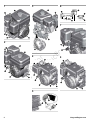 2
2
-
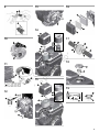 3
3
-
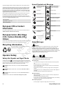 4
4
-
 5
5
-
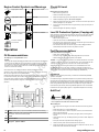 6
6
-
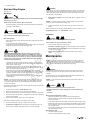 7
7
-
 8
8
-
 9
9
-
 10
10
-
 11
11
-
 12
12
-
 13
13
-
 14
14
-
 15
15
-
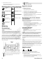 16
16
-
 17
17
-
 18
18
-
 19
19
-
 20
20
-
 21
21
-
 22
22
-
 23
23
-
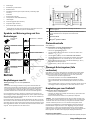 24
24
-
 25
25
-
 26
26
-
 27
27
-
 28
28
-
 29
29
-
 30
30
-
 31
31
-
 32
32
-
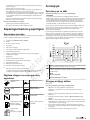 33
33
-
 34
34
-
 35
35
-
 36
36
-
 37
37
-
 38
38
-
 39
39
-
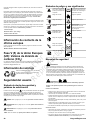 40
40
-
 41
41
-
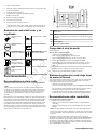 42
42
-
 43
43
-
 44
44
-
 45
45
-
 46
46
-
 47
47
-
 48
48
-
 49
49
-
 50
50
-
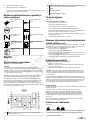 51
51
-
 52
52
-
 53
53
-
 54
54
-
 55
55
-
 56
56
-
 57
57
-
 58
58
-
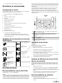 59
59
-
 60
60
-
 61
61
-
 62
62
-
 63
63
-
 64
64
-
 65
65
-
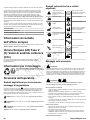 66
66
-
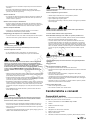 67
67
-
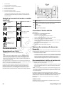 68
68
-
 69
69
-
 70
70
-
 71
71
-
 72
72
-
 73
73
-
 74
74
-
 75
75
-
 76
76
-
 77
77
-
 78
78
-
 79
79
-
 80
80
-
 81
81
-
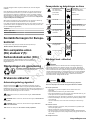 82
82
-
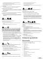 83
83
-
 84
84
-
 85
85
-
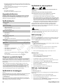 86
86
-
 87
87
-
 88
88
-
 89
89
-
 90
90
-
 91
91
-
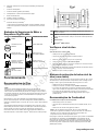 92
92
-
 93
93
-
 94
94
-
 95
95
-
 96
96
-
 97
97
-
 98
98
-
 99
99
-
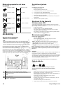 100
100
-
 101
101
-
 102
102
-
 103
103
-
 104
104
-
 105
105
-
 106
106
-
 107
107
-
 108
108


Simplicity 13H132-0123-B8 Användarmanual
- Kategori
- Tillbehör till motorfordon
- Typ
- Användarmanual
på andra språk
- italiano: Simplicity 13H132-0123-B8 Manuale utente
- español: Simplicity 13H132-0123-B8 Manual de usuario
- Deutsch: Simplicity 13H132-0123-B8 Benutzerhandbuch
- português: Simplicity 13H132-0123-B8 Manual do usuário
- français: Simplicity 13H132-0123-B8 Manuel utilisateur
- English: Simplicity 13H132-0123-B8 User manual
- dansk: Simplicity 13H132-0123-B8 Brugermanual
- suomi: Simplicity 13H132-0123-B8 Ohjekirja
- Nederlands: Simplicity 13H132-0123-B8 Handleiding
Relaterade papper
-
Simplicity 13H332-5137-H8 Användarmanual
-
-
Simplicity ENGINE, MODELS 120000 200000, VANGUARD Användarmanual
-
-
Simplicity MANUAL, OPERATOR'S Användarmanual
-
Simplicity 13H332-1157-H8 Användarmanual
-
Simplicity 25V332-0020-F1 Användarmanual
-
-
-
Simplicity ENG, MDL 10V300 12V300 Användarmanual