Yamaha RX-A1010 Bruksanvisning
- Kategori
- AV-mottagare
- Typ
- Bruksanvisning
Denna manual är också lämplig för

Check that the following accessories are supplied with this product.
You need to separately prepare the following cables to build the system based on this
document.
■ Speaker cables (depending on the number of speakers)
■ HDMI cable (x 2)
■ Audio pin cable (x 1)
■ Digital optical cable or stereo pin cable (x 1) (unnecessary if your TV supports ARC)
1 Preparations
Accessories
Cables necessary for connections
■ CD-ROM
(Owner’s Manual)
■ Safety Brochure ■ Easy Setup Guide
(this document)
■ Remote control ■ Batteries (AAA, R03, UM-4) (x 2)
Insert into the remote control in the correct polarity (+/-).
* The figure of the supplied power cable differs
depending on regions.
■ YPAO microphone ■ Power cable
■ AM antenna ■ FM antenna
*The figure of the supplied FM
antenna differs depending on
regions.
Easy Setup Guide
English for Canada, Europe, Asia,
Africa, Oceania and Latin America
AV Receiver
This document explains how to set up a 5.1- or 7.1-channel
system and play back surround sound of a BD/DVD on this unit.
For more information, refer to “Owner’s Manual” on the supplied
CD-ROM.
A PDF format of this guide and “Owner’s Manual” can be downloaded
from the following website.
http://download.yamaha.com/

2 En
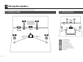
Set up the speakers in the room by using the following diagram as a reference.
For information on other speaker systems, refer to “Owner’s Manual”.
2 Placing the speakers
5.1-channel system
10°~30°10°~30°
7.1-channel system
Front speaker (L)
Front speaker (R)
Center speaker
Surround speaker (L)
Surround speaker (R)
Surround back speaker (L)
Surround back speaker (R)
Subwoofer
30 cm or more
10°~30°10°~30°

En 3
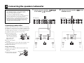
Connecting speaker cables
Speaker cables have two wires. One is for connecting
the negative (-) terminal of the unit and the speaker, and
the other is for the positive (+) terminal. If the wires are
colored to prevent confusion, connect the black wire to
the negative and the other wire to the positive.
a
Remove approximately
10 mm of insulation from
the ends of the speaker
cable, and twist the bare
wires of the cable
together firmly.
b Loosen the speaker
terminal.
c Insert the bare wires of the cable into the gap on the
side (upper right or bottom left) of the terminal.
d Tighten the terminal.
Using a banana plug
(Canada, China, Australia and General models only)
a Tighten the speaker
terminal.
b Insert a banana plug into
the end of the terminal.
1
Connect the front speakers ( / )
to the FRONT ( / ) terminals.
2
Connect the center speaker ( ) to the
CENTER terminal.
3 Connecting the speakers/subwoofer
• This unit is configured for 8-ohm speakers at the factory. When
connecting 6-ohm speakers, set the speaker impedance of this
unit to “6 Ω MIN”. For details, see “Setting the speaker
impedance” (p.16) in “Owner’s Manual”.
• Use a subwoofer equipped with built-in amplifier.
• Remove the power cable of this unit from an AC wall outlet and
turn off the subwoofer before connecting the speakers.
• Be careful that the core of the speaker cable does not touch
anything or come into contact with the metal areas of this unit.
This may damage this unit or the speakers. If the speaker
cables short circuit, “CHECK SP WIRES” will appear on the
front display when this unit is turned on.
FRONT
-
+
aa
b
b
c
c
d
d
– (black)
+ (red)
FRONT
+
aa
b
b
Banana plug
1
2
MULTI CH INPUT
ZONE OUT
CENTER
SUBWOOFERURROUND SUR. BACK
SPEAKERS
CENTER FRONTSURROUND BACKSURROUND
BI–AMP
ZONE 2/F.PRESENCE/
EXTRA SP
R L R R RL L L
SINGLE
PRE OUT
SUBWOOFERSURROUND SUR. BACK
(SINGLE)
ZONE 2
CENTER
FRONT
This unit (rear)
1
2
MULTI CH INPUT
ZONE OUT
CENTER
SUBWOOFERURROUND SUR. BACK
SPEAKERS
CENTER FRONTSURROUND BACKSURROUND
BI–AMP
ZONE 2/F.PRESENCE/
EXTRA SP
R L R R RL L L
SINGLE
PRE OUT
SUBWOOFERSURROUND SUR. BACK
(SINGLE)
ZONE 2
CENTER
FRONT
This unit (rear)

4 En
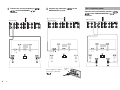
3
Connect the surround speakers ( /
) to the SURROUND ( / )
terminals.
4
Connect the subwoofer ( ) to the
SUBWOOFER (1) jack.
Use an audio pin cable to
connect the subwoofer
().
Connect the surround back speakers ( /
) to the SURROUND BACK ( / )
terminals.
1
2
MULTI CH INPUT
ZONE OUT
CENTER
SUBWOOFERURROUND SUR. BACK
SPEAKERS
CENTER FRONTSURROUND BACKSURROUND
BI–AMP
ZONE 2/F.PRESENCE/
EXTRA SP
R L R R RL L L
SINGLE
PRE OUT
SUBWOOFERSURROUND SUR. BACK
(SINGLE)
ZONE 2
CENTER
FRONT
This unit (rear)
1
2
MULTI CH INPUT
ZONE OUT
CENTER
SUBWOOFERURROUND SUR. BACK
SPEAKERS
CENTER FRONTSURROUND BACKSURROUND
BI–AMP
ZONE 2/F.PRESENCE/
EXTRA SP
R L R R RL L L
SINGLE
PRE OUT
SUBWOOFERSURROUND SUR. BACK
(SINGLE)
ZONE 2
CENTER
FRONT
This unit (rear)
(
SINGLE
)
SUBWOOFER
PRE OUT
CENTER
CENTER
SUR. BACKSURRUND
1
2
FRONT
Audio pin
cable
For 7.1-channel system
1
2
MULTI CH INPUT
ZONE OUT
CENTER
SUBWOOFERURROUND SUR. BACK
SPEAKERS
CENTER FRONTSURROUND BACKSURROUND
BI–AMP
ZONE 2/F.PRESENCE/
EXTRA SP
R L R R RL L L
SINGLE
PRE OUT
SUBWOOFERSURROUND SUR. BACK
(SINGLE)
ZONE 2
CENTER
FRONT
This unit (rear)

En 5
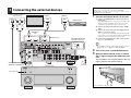
4 Connecting the external devices
+12V 0.1A MAX.
AC IN
TRIGGER
OUT
DOCK
FM
75Ω
ANTENNA
YP
B
P
R
OPTICAL
AV OUT
R
L
HDMI OUT
ARC
1
1
2
2
HDMI
(1 BD/DVD)
MONITOR OUT/ZONE OUT
IN OUT
AV 1 AV 2 AV 3 AV 4 AV 5 AV 6 AV 7
1
2
REMOTE
AV 3 AV 4AV 2AV 1
AUDIO 4
MULTI CH INPUT
ZONE OUT
AUDIO 3AUDIO 2
(3 CD)
AUDIO 1
(2 TV)
(1 BD/DVD)
CENTER
SUBWOOFER
ZONE 2
FRONT
SURROUND SUR. BACK
SPEAKERS
CENTER FRONTSURROUND BACKSURROUND
BI–AMP
ZONE 2/F.PRESENCE/
R
5
OPTICAL
4
OPTICAL
3
COAXIAL
2
COAXIAL
1
COAXIAL
6
L R R RL L L
SINGLE
RS-232C
AM
(4 RADIO)
PHONO
NETWORK
PRE OUT
SUBWOOFER
CENTER
FRONT
SURROUND SUR. BACK
(SINGLE)
GND
EXTRA SP
YP
B
P
R
YP
B
P
R
MONITOR OUT/
ZONE OUT
AV 1
AV 3
COMPONENT VIDEO
A
AV 2
B
C
AV 4
D
VOLTAGE SELECTOR
220V-
240V
110V-
120V
(1 BD/DVD)
AV 1
HDMI OUT
ARC
12
HDMI HDMI
HDMI
HDMI
HDMI
a
d
c
HDMI
b
OPTICAL
AUDIO 1
(2 TV)
5
OPTICAL
SCENE
MULTI ZONE
HDMI IN
VIDEO AUX
TONE/BALANCEOPTIONON SCREEN
DISPLAYRETURN
STRAIGHT
1
ENTER
ZONE 2
2 3 4
ZONE CONTROL
INFO MEMORY
YPAO MIC
PHONES
SILENT CINEMA
USB
iPod/iPhone
PROGRAM CATEGORY
FM AM
TUNING/CH
PRESET
ROPTICALLAUDIOVIDEOS VIDEO
PURE DIRECT
VOLUMEINPUT
MAIN ZONE
NATURAL SOUND AV RECEIVER RX-A1010
L
R
L
R
L
R
O
O
Audio out (digital optical or
analog stereo)
TV
HDMI in HDMI out
BD/DVD player
HDMI (AV1) jack
HDMI OUT 1
jack
AUDIO1
(OPTICAL or AUDIO) jack
Turn on this unit
This unit (front)
To an AC
wall outlet
VOLTAGE SELECTOR
(General model only)
This unit (rear)
1
Connect the external devices to this unit.
a Connect the BD/DVD player and this unit with an
HDMI cable.
If the BD/DVD player is currently connected to the
TV directly with an HDMI cable, disconnect the
cable from the TV and connect it to this unit.
b Connect the TV and this unit with another HDMI
cable.
c Connect the TV and this unit with a digital optical
cable or a stereo pin cable.
This connection is required to play back TV audio
on this unit. If your TV supports ARC (Audio Return
Channel), this connection is unnecessary.
d Connect the supplied power cable to this unit and
then to an AC wall outlet.
• For information on how to connect radio antennas or other
external devices, see “SETUP” in “Owner’s Manual”.
2
Turn on this unit, TV and BD/DVD player.
3
With the remote control of the TV, switch
the TV input to display the video from this
unit.
The connections are complete. Move to the next
page to optimize the speaker settings.
Before connecting the power cable (General model only)
Make sure you set the switch position of VOLTAGE
SELECTOR according to your local voltage. Voltages are AC
110-120/220-240 V, 50/60 Hz.
Opening the front panel door
Press the bottom of the door gently.

6 En
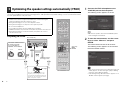
By using the Yamaha Parametric room Acoustic Optimizer (YPAO) function, this unit automatically detects speaker
connections and distances from the listening position, and optimizes the speaker settings such as volume balance and
acoustic parameters to suit your room.
Preparing for YPAO
5
Optimizing the speaker settings automatically (YPAO)
• During the measuring process, the test tones are output at high volume. Take care
that the test tone does not frighten small children. Also, refrain from using this
function at night when it may be a nuisance to others.
• During the measuring process, you cannot adjust the volume.
• During the measuring process, keep the room as quiet as possible.
• Do not connect headphones.
• If your subwoofer supports the auto-standby function, disable it.
• YPAO measurement is not performed correctly when any obstacles are in the room.
• During the measuring process (about 3 minutes), keep stuff in the corners or
remove it from the room.
1
Connect the YPAO microphone to the
YPAO MIC jack on the front panel.
The following screen appears on the TV.
• To cancel the operation, disconnect the YPAO microphone
before starting the measurement.
2
To start the measurement, use the cursor
keys to select “Measure” and press
ENTER.
The measurement will start in 10 seconds.
The following screen appears on the TV when
the measurement finishes.
• If any error message (such as E-1) or warning message (such
as W-2) appears, see “Error messages” (p.46) or “Warning
messages” (p.47) in “Owner’s Manual”.
• If the warning message “W-1:Out of Phase” appears, see “If
‘W-1:Out of Phase’ appears” (next page).
VOLUME HIGH CUT
CROSSOVER/
MIN MAXMIN MAX
SCENE
RETURN
VOLUME
SUR. DECODE
STRAIGHT
ENHANCERSLEEP PURE DIRECT
AV
AUDIO
123
67
4
V-AUX
5
FM
INFO
MEMORY
AM
PRESET
PA RT Y
MOVIE MUSIC
1 234
TV
CD
RADIO
MUTE
ENTER
7856
90
10
1234
MODE
ENT
HDMI OUT
TV
TV VOL TV CH
TOP
MENU
POP-UP
MENU
DISPLAY
SOURCE
MAIN
ZONE 2
RECEIVER
CODE SET
INPUT
MUTE
DOCK
PHONO
OPTIONON SCREEN
1234
MULTI
TUNER
TUNING
NET USB
BD/DVD
S
CEN
E
V
O
L
UME
SU
R
.
DE
CO
D
E
S
TRAI
G
H
T
ENHANCE
R
S
LEE
P
PURE DIRECT
AV
AU
D
I
O
2
1
3
7
6
4
V
-
AU
X
5
FM
I
NF
O
M
EM
O
R
Y
AM
P
RE
S
E
T
PA
RT
Y
M
O
V
IE
M
US
I
C
1
2
3
4
TV
C
D
RADI
O
M
UT
E
7
8
5
6
9
0
10
1
2
3
4
M
O
DE
ENT
HDMI
OU
T
TV
TV
VO
LT
V
C
H
T
O
P
M
EN
U
PO
P-UP
M
EN
U
DISPLA
Y
A
A
SOU
R
C
E
MAI
N
Z
O
NE
2
RECEIVER
CO
DE
SE
T
INPU
T
MU
T
E
D
OCK
PHON
O
O
PTI
ON
O
N
SC
REEN
2
1
43
MU
LT
I
TUNER
T
U
NIN
G
NET
U
S
B
B
D
/
DV
D
This unit (front)
Place the YPAO microphone at ear
height in your listening position. We
recommend using a tripod to adjust the
height. You can use the tripod screws to
fix the microphone in place.
YPAO microphone
Listening position
Ear height
Cursor keys
ENTER
RETURN
Turned on the subwoofer and set
the volume to half. If the
cross-over frequency is
adjustable, set it to maximum.
Turned on the subwoofer and set
the volume to half. If the
cross-over frequency is
adjustable, set it to maximum.

En 7
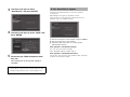
3
Use the cursor keys to select
“Save/Cancel” and press ENTER.
4
Use the cursor keys to select “SAVE” and
press ENTER.
5
Disconnect the YPAO microphone from
this unit.
Now optimization of the speaker settings is
complete.
Follow the procedure below to check the speaker
connections.
Depending on the type of speakers or room
environment, this message may appear even if the
speakers are connected correctly.
a Use the cursor keys to select “Result” and press ENTER.
b Use the cursor keys to select “Wiring”.
c Check the cable connections (+/-) of the speaker
indicated with “Reverse”.
If the speaker is connected correctly:
You can save the current settings.
Press RETURN and proceed to step 3.
If the speaker is connected incorrectly:
Turn off this unit, reconnect the speaker cable, and then
try YPAO measurement again.
• Since the YPAO microphone is sensitive to heat, do not place
the microphone in any place where it will be subjected to direct
sunlight or high temperatures (top of an AV equipment, etc).
If “W-1: Out of Phase” appears

© 2011 Yamaha Corporation YD503B0/ESEN2
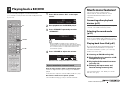
Now let’s play back a BD/DVD.
We recommend playing back multichannel audio
(5.1-channel or more) to feel surround sound produced
by this unit.
1
Press AV1 to select “AV1” as the input
source.
2
Start playback on the BD/DVD player.
3
Press STRAIGHT repeatedly to select
“STRAIGHT”.
• When “STRAIGHT” (straight decode) is enabled, each
speaker produces each channel audio signal directly (without
sound field processing). If you play back 5.1-channel audio on
the 7.1-channel system, no sounds will be heard from the
surround back speakers.
4
Press VOLUME to adjust the volume.
Now the basic setup procedure is complete.
Only the front speakers work on multichannel audio
Check the digital audio output setting on the BD/DVD
player.
It may be set to output 2-channel audio (PCM, etc.) only.
No sound is heard from a specific speaker
See “Troubleshooting” (p.123) in “Owner’s Manual”.
6 Playing back a BD/DVD
SCENE
RETURN
VOLUME
SUR. DECODE
STRAIGHT
ENHANCERSLEEP PURE DIRECT
AV
AUDIO
123
67
4
V-AUX
5
FM
INFO
MEMORY
AM
PRESET
PA RT Y
MOVIE MUSIC
1 234
TV
CD
RADIO
MUTE
ENTER
7856
90
10
1234
MODE
ENT
HDMI OUT
TV
TV VOL TV CH
TOP
MENU
POP-UP
MENU
DISPLAY
SOURCE
MAIN
ZONE 2
RECEIVER
CODE SET
INPUT
MUTE
DOCK
PHONO
OPTIONON SCREEN
1234
MULTI
TUNER
TUNING
NET USB
BD/DVD
S
CEN
E
R
ET
U
RN
SUR
.
DECODE
ENHAN
C
E
R
S
LEE
P
PURE DIRE
C
T
AV
AU
D
I
O
2
3
7
6
4
V
-
AU
X
5
FM
I
NF
O
M
EM
O
R
Y
AM
P
RE
S
E
T
PA
RT
Y
M
O
VI
E
M
US
I
C
1
2
3
4
TV
C
D
RADI
O
M
UT
E
ENTE
R
7
8
5
6
9
0
10
1
2
3
4
M
O
DE
EN
T
HDMI
OU
T
TV
T
V
VO
LT
V
C
H
T
O
P
M
EN
U
PO
P-
U
P
MENU
DISPLA
Y
A
A
S
OURCE
MAI
N
Z
O
NE
2
RECEIVER
CO
DE
SE
T
INPU
T
MU
T
E
D
OCK
PHON
O
O
PTI
ON
O
N
SC
REEN
2
1
4
3
MU
LT
I
TUNER
T
U
NIN
G
NET
U
S
B
B
D
/
DV
D
AV1
STRAIGHT
VOLUME
If you cannot have surround sound
OUT
1
IN
OUT
2
VOLUME
MUTE
DRCADAPTIVE
3
ZONE
2
STEREO
ENHANCER
SLEEP
HD
TUNED
PRE
AMP
PAR TY
ZONE
3
ZONE
4
HD
TAG
DOCK
SBLPL SBRSBPR
SW1
SL
SW2SW
SR
PL
CLR
PR
A.Sel:Auto
AV1
SPIMP.-
OUT
1
IN
OUT
2
VOLUME
MUTE
DRCADAPTIVE
3
ZONE
2
STEREO
ENHANCER
SLEEP
HD
TUNED
PRE
AMP
PAR TY
ZONE
3
ZONE
4
HD
TAG
DOCK
SBLPL SBRSBPR
SW1
SL
SW2SW
SR
PL
CLR
PR
A.Sel:Auto
STRAIGHT
SPIMP.-
OUT
1
IN
OUT
2
VOLUME
MUTE
DRCADAPTIVE
3
ZONE
2
STEREO
ENHANCER
SLEEP
HD
TUNED
PRE
AMP
PAR TY
ZONE
3
ZONE
4
HD
TAG
DOCK
SBLPL SBRSBPR
SW1
SL
SW2SW
SR
PL
CLR
PR
Main:Volume
SPIMP.-
Much more features!
This unit has various other functions.
Please refer to “Owner’s Manual” on the
supplied CD-ROM and utilize this unit
effectively.
Connecting other playback
devices (p.31)
Connect audio devices (CD player, etc.), game
console, camcorder, and many others.
Selecting the sound mode
(p.51)
Select the desired sound program (CINEMA
DSP) or surround decoder suitable for movies,
music, games, sports programs and other uses.
Playing back from iPod (p.61)
By using a USB cable supplied with iPod, an
optional Yamaha iPod dock or an optional
Yamaha iPod wireless system, you can enjoy
iPod music on this unit.
■ Listening to FM/AM radio (p.56)
■ Playing back music stored on a USB
storage device (p.68)
■ Playing back the network contents
(p.71 to p.74)
■ Selecting the input source and
favorite settings at once (p.49)
For more information, see “What you can do
with this unit” (p.6).
-
 1
1
-
 2
2
-
 3
3
-
 4
4
-
 5
5
-
 6
6
-
 7
7
-
 8
8


Yamaha RX-A1010 Bruksanvisning
- Kategori
- AV-mottagare
- Typ
- Bruksanvisning
- Denna manual är också lämplig för
på andra språk
- italiano: Yamaha RX-A1010 Manuale del proprietario
- español: Yamaha RX-A1010 El manual del propietario
- Deutsch: Yamaha RX-A1010 Bedienungsanleitung
- português: Yamaha RX-A1010 Manual do proprietário
- français: Yamaha RX-A1010 Le manuel du propriétaire
- Türkçe: Yamaha RX-A1010 El kitabı
- English: Yamaha RX-A1010 Owner's manual
- dansk: Yamaha RX-A1010 Brugervejledning
- русский: Yamaha RX-A1010 Инструкция по применению
- suomi: Yamaha RX-A1010 Omistajan opas
- Nederlands: Yamaha RX-A1010 de handleiding
- română: Yamaha RX-A1010 Manualul proprietarului