
Owner’s Manual
Mode d’emploi
Bedienungsanleitung
M
MIXING CONSOLE

2
Introduction
Thank you for purchasing the Yamaha M3000 mixing console. The M3000
is based on Yamaha’s experience with the PM series, and features superb
sound quality with a full range of functionality such as VCA faders, scene
memory, and GA diversity. In order to take full advantage of the M3000’s
performance and enjoy long and trouble-free use, please read this manual
carefully.
Note:
This manual assumes that you are thoroughly familiar with basic
operation of mixing consoles and their terminology.
FCC INFORMATION (U.S.A.)
1. IMPORTANT NOTICE: DO NOT MODIFY THIS UNIT! This product, when installed as indicated in the instructions contained in this manual, meets FCC
requirements. Modifications not expressly approved by Yamaha may void your authority, granted by the FCC, to use the product.
2. IMPORTANT: When connecting this product to accessories and/or another product use only high quality shielded cables. Cable/s supplied with this product MUST
be used. Follow all installation instructions. Failure to follow instructions could void your FCC authorization to use this product in the USA.
3. NOTE: This product has been tested and found to comply with the requirements listed in FCC Regulations, Part 15 for Class “B” digital devices. Compliance with
these requirements provides a reasonable level of assurance that your use of this product in a residential environment will not result in harmful interference with
other electronic devices. This equipment generates/uses radio frequencies and, if not installed and used according to the instructions found in the users manual, may
cause interference harmful to the operation of other electronic devices. Compliance with FCC regulations does not guarantee that interference will not occur in all
installations. If this product is found to be the source of interference, which can be determined by turning the unit “OFF” and “ON”, please try to eliminate the
problem by using one of the following measures: Relocate either this product or the device that is being affected by the interference. Utilize power outlets that are on
different branch (circuit breaker or fuse) circuits or install AC line filter/s. In the case of radio or TV interference, relocate/reorient the antenna. If the antenna lead-in
is 300 ohm ribbon lead, change the lead-in to coaxial type cable. If these corrective measures do not produce satisfactory results, please contact the local retailer
authorized to distribute this type of product. If you can not locate the appropriate retailer, please contact Yamaha Corporation of America, Electronic Service
Division, 6600 Orangethorpe Ave, Buena Park, CA 90620
The above statements apply ONLY to those products distributed by Yamaha Corporation of America or its subsidiaries.
NEDERLAND
●Dit apparaat bevat een lithium batterij voor geheugen
back-up.
●Raadpleeg uw leverancier over de verwijdering van de
batterij op het moment dat u het apparaat ann het einde
van de levensduur afdankt of de volgende Yamaha
Service Afdeiing:
Yamaha Music Nederland Service Afdeiing
Kanaalweg 18-G, 3526 KL UTRECHT
Tel. 030-2828425
● Gooi de batterij niet weg, maar lever hem in als KCA.
THE NETHERLANDS
●This apparatus contains a lithium battery for memory
back-up.
●For the removal of the battery at the moment of the
disposal at the end of the service life please consult your
retailer or Yamaha Service Center as follows:
Yamaha Music Nederland Service Center
Address: Kanaalweg 18-G, 3526 KL
UTRECHT
Tel: 030-2828425
●Do not throw away the battery. Instead, hand it in as
ADVARSEL!
Lithiumbatteri—Eksplosionsfare ved
fejlagtig håndtering. Udskiftning må
kun ske med batteri af samme fabrikat
og type. Levér det brugte batteri
tilbage til leverandoren.
VARNING
Explosionsfara vid felaktigt
batteribyte. Använd samma batterityp
eller en ekvivalent typ som
rekommenderas av
apparattillverkaren. Kassera använt
batteri enligt fabrikantens instruktion.
VAROITUS
Paristo voi räjähtää, jos se on
virheellisesti asennettu. Vaihda paristo
ainoastaan laitevalmistajan
suosittelemaan tyyppiin. Hävitä
käytetty paristo valmistajan ohjeiden
mukaisesti.

3
Contents
Features of the system...............................5
Control panel............................................6
Input channel section................................................6
Variable/fixed select section....................................13
Mix section..............................................................14
VCA master fader section.......................................16
STEREO A section...................................................16
STEREO B section...................................................18
Monitor section.......................................................19
Talkback section......................................................21
Meter select section.................................................22
Scene memory section ............................................22
Matrix section..........................................................24
Meter bridge............................................................25
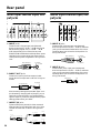
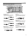
Rear panel .............................................26
Mono input channel input/output jacks ...............26
Stereo input channel input/output jacks...............26
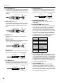
Master section input/output jacks..........................27
Output connector for illumination power
supply.......................................................................29
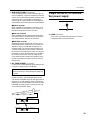
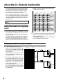
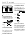
About the GA Diversity functionality........30
Using MIX buses 1–8 as group buses.....................30
Using MIX buses 1–8 as AUX buses ......................30
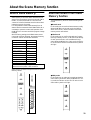
About the Scene Memory function...........31
What is scene memory?...........................................31
About the modes of the Scene Memory function..31
Operations in normal mode....................................32
Operations in check mode......................................33
Operations in utility mode......................................34
Utility items..............................................................34
Control change table ...............................................35
Using mute groups..................................................36
About the local control circuit................................37
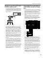
About the VCA functionality....................38
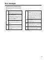
Error messages ......................................41
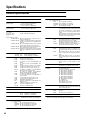
Specifications.........................................42
General specifications..............................................42
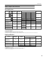
Input/output characteristics....................................43
Other ........................................................................44
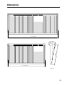
Dimensions ............................................45
MIDI data format....................................46
MIDI Implementation Chart .....................47

4
Precautions
• Connect the mixer power cord only to the power supply
unit, and connect the power supply unit to an AC outlet
of the type stated in this
Owner’s Manual
or as marked
on the power supply unit. Failure to do so is a fire and
electrical shock hazard.
• Do not locate the mixer in a place subject to excessive
heat or in direct sunlight. This could be a fire hazard.
• Do not place the mixer in a place subject to excessive
humidity or dust. This could be a fire and electrical
shock hazard.
• Do not plug several devices into the same AC outlet. This
may overload the AC outlet, and could be a fire and elec-
trical shock hazard. It may also affect the performance of
some equipment.
• Do not place heavy objects on the power cord. A dam-
aged power cord is a potential fire and electrical shock
hazard.
• If the power cord is damaged (i.e., cut or a bare wire is
exposed), ask your dealer for a replacement. Using the
mixer in this condition is a fire and shock hazard.
• Hold the power cord plug when disconnecting from an
AC outlet. Never pull the cord. Damaging the power cord
in this way is a potential fire and electrical shock hazard.
• Do not place small metal objects on top of the mixer.
Metal objects inside the mixer are a fire and electrical
shock hazard.
• Do not try to modify the mixer. This could be a fire and
electrical shock hazard.
• The mixer operating temperature is between 5˚C and
35˚C (41˚F and 95˚F).
• Turn off all audio devices and speakers when connecting
to the mixer. Refer to the owner’s manual for each device.
Use the correct cables and connect as specified.
• If you notice any abnormality—such as smoke, odor, or
noise—turn off the mixer immediately. Remove the
power cord from the AC outlet. Confirm that the abnor-
mality is no longer present. Consult your dealer for
repair. Using the mixer in this condition is a fire and
shock hazard.
• If a foreign object or water gets inside the mixer, turn it
off immediately. Remove the power cord from the AC
outlet. Consult your dealer for repair. Using the mixer in
this condition is a fire and electrical shock hazard.
• If you plan not to use the mixer for a long period of time,
remove the power cord from the AC outlet. Leaving the
mixer connected is a fire hazard.
• Do not use benzene, thinner, cleaning detergent, or a
chemical cloth to clean the mixer. Use only a soft, dry
cloth.
• The mixer is a heavy piece of equipment. Always grip the
underneath, not the side panels, when lifting.
• The mixer uses high-frequency digital circuits that may
cause interference on radios and televisions placed close
to it. If interference does occur, relocate the affected
equipment.

5
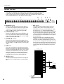
Features of the system
• The M3000-40C provides a generous number of input
modules; 40 monaural and 4 stereo (the M3000-24
provides 24 monaural and 4 stereo). Stereo output, 16
mix outputs, and 8 matrix outputs are provided in
addition. The M3000 is suitable for use in a wide
range of applications, such as the main mixer for
sound reinforcement, as a monitor mixer, or in build-
ing installations.
• The GA Diversity function allows each pair of MIX
buses 1/2–7/8 to be switched between group bus
(fixed output level from the input channels) and AUX
bus (variable output level from the input channels).
Bus configuration can be set up as needed.
• The Scene Memory function allows the on/off status
of the mono/stereo input channels, MIX OUT 1–16,
and STEREO A OUT to be saved as one of 128
“scenes.” Scenes can be selected from the front panel,
or by MIDI program change messages from an exter-
nal device. In addition, MIDI control change mes-
sages transmitted from an external device can be used
to switch the individual on/off status of input chan-
nels or bus outputs channels.
• By modifying internal settings, Scene Memory num-
bers 1–8 can be used as mute groups. In this case, up
to eight mute (on/off) settings can be added/defeated
individually.
• Eight VCA master faders allow the gain of multiple
input channels to be controlled as a group. By group-
ing the desired input channels and assigning them to a
VCA master fader, you can adjust the mix as appropri-
ate for the on-state action using the VCA master fad-
ers alone.
• The mono input channels provide a 26 dB pad, HPF,
phase switch, four-band parametric EQ, and 100 mm
full stroke faders as well as DIRECT OUT jacks. Phan-
tom power is also provided, and can be switched on/
off individually.
• The M3000-40C features a center master design that
places the master section in the middle of the mixer
for superior operability.
• All input channels provide a PFL switch, and an AFL
switch is provided for MATRIX OUT 1–8/MIX OUT
1–16/STEREO A OUT/STEREO B OUT. This makes it
easy to check your input/output sources.
• Eight independent matrices are provided. The signals
from MIX OUT 1–16/STEREO A OUT and dedicated
input jacks can be mixed at the desired levels, and out-
put from MATRIX OUT jacks 1–8. This capability can
be used for foldback or as a mix for individual speak-
ers/amps.
• All mono input channels, stereo buses, and MIX buses
provide an INSERT I/O jack. External effect proces-
sors can be inserted as necessary.
• The talkback signal and test tone oscillators can be
sent to any of the MIX buses 1-2–13/16 or the stereo
buses.
• As monitor sources for the monitor output, you can
select (in addition to STEREO A OUT), PFL from the
input channels, AFL/PFL from MATRIX OUT 1–8/
MIX OUT 1–16/STEREO A OUT/STEREO B OUT, or
2TR IN 1/2.

6
Control panel
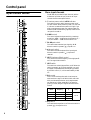
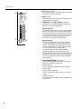
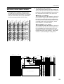
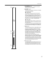
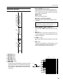
Input channel section
Mono input channels
The M3000-24 provides 24 input channels, and the
M3000-40C provides 40 input channels. All input
channels have the same specifications.
A
Phantom power switch/
+48 V
indicator
This switch turns the +48 V phantom power on/off
for each channel. When phantom power is on, the +48
V indicator located above the switch will light. If you
wish to use phantom power, first make sure that the
PHANTOM MASTER switch (page 28) located on the
rear panel is turned on.
B
GAIN
control
This control adjusts the input sensitivity. Levels sup-
ported are –16dB ~ –60 dB when the Pad switch (
3
)
is off, and +10dB ~ –34dB when the switch is on.
C
26 dB
pad switch
This switch attenuates the input signal by 26 dB.
When the switch is pressed ( ), the pad is on.
D
ø
(phase) switch
This switch reverses the phase of the input signal.
When the switch is pressed ( ), the phase is
reversed.
E
HPF
(high pass filter) control
This controls the cutoff frequency of the high pass fil-
ter. The range is 20Hz–400Hz.
F
HPF
switch
This switch turns the high pass filter on/off. When the
switch is pressed ( ), the high pass filter is on, and
the signal component below the frequency specified
by the HPF control (
5
) will be attenuated by 12 dB/
oct.
G
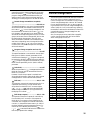
EQ
control
This is a four-band equalizer which can boost/cut
each band over range of
±
15 dB. HI-MID and LOW-
MID provide switches that let you change between
two settings of Q (filter steepness). The center fre-
quency, Q value, and gain range of each band are as
follows.
H
EQ
switch
This switches the equalizer on/off. When the switch is
pressed ( ), the equalizer is on.
GAIN
HI
HI-
MID
LO-
MID
LO
600
20090
30
+15–15
EQ
HPF
+48V
Ø
1.6k
600240
80
+15–15
8k
3k1.2k
0.4k
+15–15
20k
8k3k
1k
400
15050
20
–60–16
+15–15
100
PRE
PRE
M9
100
M10
100
M11
100
M14
PAN
M13
M12
M13/
M14
100
M16
PAN
M15
M15/
M16
100
100
100
100
100
100
PRE
PRE
M1
M2
M3
M4
M5
100
M6
100
M7
100
M8
26dB
–34
+10
1
2
3
4
5
6
8
P
P
P
O
P
J
I
7
J
L
K
M
N
Band
Center
frequency
Q Gain
HI 1 kHz–20 kHz 0.667
±
15 dB
HI-MID 0.4 kHz–8 kHz 1.41/2.88
LO-MID 80 Hz–1.6 kHz 1.41/2.88
LO 30 Hz–600 Hz 0.667

Control panel
7
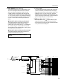
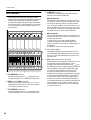
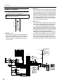
I
M1–M8
switches
These switch on/off the signal which is sent from the
input channel to MIX buses 1–8.
J
M1–M8
mix level controls
These controls send the signal from the input channel
to MIX buses 1–8. When the control is in the “
▲
”
position, the level is nominal (0 dB). Use the PRE
switch (
P
) to switch between pre/post fader.
K
M9–M12
switches
These are on/off switches for the signals that are sent
from the input channel to MIX buses 9–12.
L
M9–M12
mix level controls
These controls send the signal from the input channel
to MIX buses 9–12. When the control is in the “
▲
”
position, the level is nominal (0 dB). Use the PRE
switch (
P
) to switch between pre/post fader.
M
M13/M14
,
M15/M16
switches
These are on/off switches for the signals that are sent
from the input channel to MIX buses 13–16. M13 and
14, and M15 and M16 are stereo pairs, and each pair is
turned on/off by one switch. Use the PRE switch (
P
)
to switch between pre/post fader.
N
M13/M14
,
M15/M16
mix level controls
These controls send the signal from the input channel
to MIX buses 13–16. When the control is in the “
▲
”
position, the level is nominal (0 dB). M13 and M14,
and M15 and M16 are stereo pairs, and the output
level of each pair is controlled by one knob. Use the
PRE switch (
P
) to switch between pre/post fader.
O
M13/M14
,
M15/M16
pan controls
These controls set the panning of the signals that are
sent from the input channel to MIX buses 13/14 or
MIX buses 15/16. When the control is in the center
position, an equal amount of signal will be sent to
both buses.
P
PRE
switches
These are pre-fader/post-fader switches for the signals
that are sent from the input channel to MIX buses 1–
16. Pre/post can be switched independently for each
group of MIX buses: 1–4, 5–8, 9–12, and 13–16. When
the switch is pressed ( ), the post-EG/pre-fader sig-
nal will be sent to the corresponding group of MIX
buses.
Note:
If these switches are off, no signal will be sent
to the corresponding MIX bus from this input
channel, regardless of the switch setting of the vari-
able/fixed select section (page 13).
Note:
For MIX bus pairs for which the variable/fix
select section (page 13) switch is set to FIX, the out-
put level which is sent from each input channel to
the bus will be fixed, and therefore the mix level
control setting will have no effect.
from Ctrl Master
from VCA Master
ON/EDIT
CHECK ON
CONTROL
ST
L R
PFL
L R ON
MIX
(FIX)
MIX
(VARIABLE)
M8
M7
M6
M5
PRE
M4
M3
M2
8
7
2
1
PFL
DIRECT OUT
Internal Jumper
PRE
M15/
M16
M13/
M14
PAN
PAN
M12
M11
M10
M9
PRE
PRE
M1
PEAK
NOM
SIGNAL
ST
VCA
INSERT I/O
4 Stage EQ
EQHPF
HPF
PHANTOM
MASTER
+48V
Input
1-24/1-40
+48V
26dB
PAD
PAN
HA
GAIN
1 2 3 4 5 6 7 81 3 5 7 9
2 4 6 8
11 13 15
10 12 14 16
f
g
f
g
f
g
Q
f
g
Q
LO
LO-MID
HI-MID
HI

Control panel
8
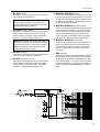
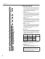
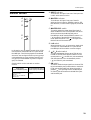
Q
ST
(stereo) switch
When this switch is on, the signal of the input channel
will be sent to the (ST) stereo bus.
R
PAN
control
This sets the panning of the signal that is sent from the
input channel to the ST bus.
S
ON/EDIT
switch/
ON
,
CHECK
indicators
The function of this switch and these indicators will
depend on the mode of the M3000.
●
In normal mode
The ON/EDIT switch will turn on the input channel.
When on, the ON indicator will light. Channels which
are turned off will send no signal to the ST bus or the
MIX buses. However even in this case, you can use the
PFL switch (
W
) to monitor the channel from the
MONITOR OUT jacks or the PHONE jack.
●
In check mode
In check mode (page 33), you can use the CHECK
indicators to view the on/off status of each channel
stored in a scene before you actually recall the scene.
This is convenient when you wish to verify the status
of each channel before you recall a scene.
In check mode, you can also use the ON/EDIT
switches to change only the lit/dark status of the
CHECK indicators. (The actual on/off setting will not
be affected.) Use this when you wish to maintain the
current mix settings, and store partially modified set-
tings as a scene.
T
PEAK/NOM/SIGNAL
indicators
Three indicators show the level of the input channel
signal after it passes through the EQ.
• PEAK indicator
This will light when the signal exceeds the nominal
level by 18 dB.
• NOM (nominal) indicator
This will light when the signal reaches nominal level
(0 dB).
• SIGNAL indicator
This will light when the signal reaches 10 dB below the
nominal level.
ON/
EDIT
CHECK
ON
PEAK
NOM
SIGNAL
PFL
1
2
3
4
5
6
7
8
VCA
GROUP
10
5
0
5
10
20
30
40
50
60
ST
PAN
RL
R
V
Q
S
U
W
T

Control panel
9
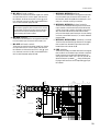
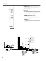
U VCA GROUP select switches
These switches select the VCA master fader(s) which
will control the signal output level of this channel.
When you select a VCA group 1–8, the indicator
located at the left of each switch will light, and the
corresponding VCA master fader (VCA master section
3) will control the channel. It is possible to select two
or more VCA groups for one input channel, or to con-
trol two or more input channels by the same VCA
group.
●Channels for which a VCA group is selected
The signal output level of the channel can be con-
trolled both by the corresponding VCA master
fader(s) and by the channel fader (V). The settings of
all corresponding VCA master faders are summed
with the setting of the channel fader to specify the sig-
nal output level of that channel.
●Channels for which a VCA group is not selected
The signal output level of the channel can be con-
trolled only by the channel fader (V).
V Channel fader
This fader adjusts the signal output level of the input
channel. This fader will affect the level of the signal
that is sent to the ST bus and to the MIX buses (if the
PRE switch is off). If one or more VCA groups are
selected by the VCA GROUP select switches (U), the
signal output level of that channel will also be affected
by the corresponding VCA master fader(s).
W PFL (pre-fader listen) switch
When this switch is on ( ), the pre-fader/post-EQ
signal of this input channel will be sent to the PFL
bus, allowing it to be monitored from the MONITOR
OUT jacks or the PHONES jack.
Note: For details on VCA functions, refer to
page 38.
from Ctrl Master
from VCA Master
ON/EDIT
CHECK ON
CONTROL
ST
L R
PFL
L R ON
MIX
(FIX)
MIX
(VARIABLE)
M8
M7
M6
M5
PRE
M4
M3
M2
8
7
2
1
PFL
DIRECT OUT
Internal Jumper
PRE
M15/
M16
M13/
M14
PAN
PAN
M12
M11
M10
M9
PRE
PRE
M1
PEAK
NOM
SIGNAL
ST
VCA
INSERT I/O
4 Stage EQ
EQHPF
HPF
PHANTOM
MASTER
+48V
Input
1-24/1-40
+48V
26dB
PAD
PAN
HA
GAIN
1 2 3 4 5 6 7 81 3 5 7 9
2 4 6 8
11 13 15
10 12 14 16
f
g
f
g
f
g
Q
f
g
Q
LO
LO-MID
HI-MID
HI

Control panel
10
Stereo input channels
The M3000 provides four stereo input channels. Ste-
reo sound sources such as sub-mixers, effect proces-
sor, or CD players can be input to the INPUT A jacks
(XLR connectors) or INPUT B jacks (RCA phono
connectors) located on the rear panel.
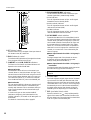
A GAIN A control
This control adjusts the input sensitivity of the signal
that is input from the XLR connector INPUT A jack
(rear panel 4). The level range is +10~ –30 dB. When
the A/B select switch (3) is in the B position ( ),
this control will have no effect.
B GAIN B control
This control adjusts the input sensitivity of the signal
that is input from the RCA phono connector INPUT
B jack (rear panel 5). The level range is +10~ –20 dB.
When the A/B select switch (3) is in the A position
( ), this control will have no effect.
C A/B select switch
This switch selects the input jacks that the stereo input
channel will use. When the switch is in the upward
position ( ) the INPUT A jack can be used. When
the switch is in the downward position ( ) the
INPUT B jacks can be used.
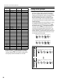
D EQ controls
This is a four-band equalizer which allows ±15 dB of
boost/cut for each band. The HI-MID and LOW-MID
bands allow you to switch between two settings of Q
(steepness). The center frequency, Q values, and gain
range for each band is as follows.
E EQ switch
This switches the equalizer on/off. The equalizer is on
when the switch is pressed down ( ).
F M1–M8 switches
These switch on/off the signal which is sent from the
stereo input channel to MIX buses 1–8.
–30+10
+15–15
A
–20+10
B
GAIN
HI
A
B
+15–15
HI-
MID
+15–15
LO-
MID
+15–15
100
100
100
100
100
LO
EQ
PRE
PRE
M1
M2
M3
M4
M5
100
M6
100
M7
100
M8
100
PRE
PRE
M9
100
M10
100
M11
100
M14
BAL
M13
M12
M13/
M14
100
M16
BAL
M15
M15/
M16
100
A
B
C
E
M
M
M
I
L
M
G
F
D
G
H
J
K
Band
Center
frequency
Q Gain
HI 20 kHz 0.667
±15 dB
HI-MID 3 kHz 1.41/2.88
LO-MID 800 Hz 1.41/2.88
LO 50 Hz 0.667
Note: If these switches are off, no signal will be sent
to the corresponding MIX bus from this input
channel, regardless of the switch setting of the vari-
able/fixed select section (page 13).

Control panel
11
G M1–M8 mix level controls
These controls combine the stereo signal from the ste-
reo input channel into a mono signal, and send it to
MIX buses 1–8. When the control is in the “▲” posi-
tion, the level is nominal (0 dB). Use the PRE switch
(M) to switch between pre/post fader.
H M9–M12 switches
These are on/off switches for the signals that are sent
from the stereo input channel to MIX buses 9–12.
I M9–M12 mix level controls
These controls combine the stereo signal from the ste-
reo input channel into a mono signal, and send it to
MIX buses 9–12. When the control is in the “▲” posi-
tion, the level is nominal (0 dB). Use the PRE switch
(M) to switch between pre/post fader.
J M13/M14, M15/M16 switches
These are on/off switches for the signals that are sent
from the stereo input channel to MIX buses 13–16.
M13 and 14, and M15 and M16 are stereo pairs, and
each pair is turned on/off by one switch.
K M13/M14, M15/M16 mix level controls
These controls send the stereo signal from the stereo
input channel to MIX buses 13/14, 15/16. When the
control is in the “▲” position, the level is nominal (0
dB). M13 and M14, and M15 and M16 are stereo
pairs, and the output level of each pair is controlled by
one knob. Use the PRE switch (P) to switch between
pre/post fader.
L M13/M14, M15/M16 BAL (balance) controls
These controls set the left/right balance of the signals
that are sent from the stereo input channel to MIX
buses 13/14 or MIX buses 15/16.
M PRE switches
These are pre-fader/post-fader switches for the signals
that are sent from the stereo input channel to the MIX
buses. Pre/post can be switched independently for
each group of MIX buses: 1–4, 5–8, 9–12, and 13–16.
When the switch is pressed ( ), the pre-fader/post-
EQ signal will be sent to the corresponding group of
MIX buses.
Note: For MIX bus pairs for which the variable/fix
select section (page 13) switch is set to FIX, the out-
put level which is sent from each input channel to
the bus will be fixed, and therefore the mix level
control setting will have no effect.
ST
L R
PFL
L R ON
MIX
(FIX)
MIX
(VARIABLE)
1 2 3 4 5 6 7 81 3 5 7 9
2 4 6 8
11 13 15
10 12 14 16
1
2
7
8
from VCA Master
CONTROL
ONCHECK
ON/EDIT
from Ctrl Master
B
A
M15
M16
HA
HA
GAIN A GAIN A
BAL
M13
M14
BAL
PRE
M1
PRE
PRE
M9
M10
M11
M12
PFL
M2
M3
M4
PRE
M5
M6
M7
M8
BAL
VCA
ST CH
1-4
INPUT A
INPUT B
R
L
R
L
4 Stage EQ
HA
HA
EQ
4 Stage EQ
VCA
ST
PEAK
NOM
SIGNAL
LO
LO-MID
HI-MID
HI
g
Q
g
g
g
Q

Control panel
12
N ST (stereo) switch
When this switch is on, the signal of the input channel
will be sent to the (ST) stereo bus.
O BAL (balance) control
This sets the left/right balance of the signal that is sent
from the input channel to the ST bus.
P ON/EDIT switch/ON, CHECK indicators
The function of this switch and these indicators will
depend on the mode of the M3000.
●In normal mode
The ON/EDIT switch will turn on the stereo input
channel. When on, the ON indicator will light. Chan-
nels which are turned off will send no signal to the ST
bus or the MIX buses. However even in this case, you
can use the PFL switch (T) to monitor the channel
from the MONITOR OUT jacks or the PHONE jack.
●In check mode
You can use the CHECK indicators to view the on/off
status of each channel stored in a scene before you
actually recall the scene. This is convenient when you
wish to verify the status of each channel before you
recall a scene.
In check mode, you can also use the ON/EDIT
switches to change only the lit/dark status of the
CHECK indicators. (The actual on/off setting will not
be affected.)
For details on Check mode, refer to page 33.
Q PEAK/NOM/SIGNAL indicators
Three indicators show the level of the stereo input
channel signal after it passes through the EQ.
• PEAK indicator
This will light when the sum of the L and R signals
exceeds the nominal level by 18 dB.
• NOM (nominal) indicator
This will light when the sum of the L and R signals
reaches nominal level (0 dB).
• SIGNAL indicator
This will light when the sum of the L and R signals
reaches 10 dB below the nominal level.
R VCA GROUP select switches
These switches select the VCA master fader(s) which
will control the signal output level of this stereo input
channel. When you select a VCA group 1–8, the indi-
cator located at the left of each switch will light, and
the corresponding VCA master fader (VCA master
section 3) will control the channel. It is possible to
select two or more VCA groups for one stereo input
channel, or to control two or more channels by the
same VCA group.
●Stereo input channels for which a VCA group is
selected
The signal output level of the channel can be con-
trolled both by the corresponding VCA master
fader(s) and by the channel fader (S).
●Stereo input channels for which a VCA group is
not selected
The signal output level of the stereo input channel can
be controlled only by the channel fader (S).
S Channel fader
This fader adjusts the signal output level of the stereo
input channel. This fader will affect the level of the
signal that is sent to the ST bus and to the MIX buses
(if the PRE switch is off). If one or more VCA groups
are selected by the VCA GROUP select switches (R),
the signal output level of that channel will also be
affected by the corresponding VCA master fader(s).
T PFL (pre-fader listen) switch
When this switch is on ( ), the pre-fader/post-EQ
signal of this stereo input channel will be sent to the
PFL bus, allowing it to be monitored from the MONI-
TOR OUT jacks or the PHONES jack.
ST
ON/
EDIT
PFL
CHECK
ON
PEAK
NOM
SIGNAL
BAL
RL
1
2
3
4
5
6
7
8
VCA
GROUP
10
5
0
5
10
20
30
40
50
60
O
S
N
P
R
T
Q
Note: For details on VCA functions, refer to
page 38.

Control panel
13
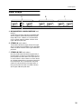
Variable/fixed select section
The M3000’s GA (Group/Aux) diversity function
allows MIX buses 1–8 to function either as group
buses or as AUX buses. In this section, you can switch
each pair of MIX buses (1/2, 3/4, 5/6, 7/8) between
functioning as group buses or as AUX buses.
A Variable/fixed select switches
These switches select whether the level of the signals
sent from the input channels to MIX buses 1–8 will be
fixed (FIX) or variable (VARIABLE). From top to bot-
tom, these switch MIX buses 1/2, 3/4, 5/6 and 7/8.
●When FIX ( ) is selected
The corresponding pair of MIX buses (1/2, 3/4, 5/6, 7/
8) will function as a group bus, and the signal of the
MIX (FIX) bus will be output to the corresponding
mix channel. In this case, the settings of the mix level
controls M1–M8 (mono input channels J, stereo
input channels 7) will have no effect.
●When VARIABLE ( ) is selected
The corresponding pair of MIX buses (1/2, 3/4, 5/6, 7/
8) will function as an AUX bus, and the signal of the
MIX (VARIABLE) bus will be output to the corre-
sponding mix channel. In this case, the mix level con-
trols M1–M8 (mono input channels J, stereo input
channels 7) will take effect just as they are set.
+15–15
100
100
100
100
100
EQ
PRE
PRE
M1
M2
M3
M4
M5
100
M6
100
M7
100
M8
VARIABLE
FIX
+15–15
100
100
100
100
100
EQ
PRE
PRE
M1
M2
M3
M4
M5
100
M6
100
M7
100
M8
+15–15
100
100
100
100
100
EQ
PRE
PRE
M1
M2
M3
M4
M5
100
M6
100
M7
100
M8
+15–15
100
100
100
100
100
EQ
PRE
PRE
M1
M2
M3
M4
M5
100
M6
100
M7
100
M8
1
(SUB)(ST)
from INPUT
MIX 3-4, 5-6, 7-8: Same as MIX 1-2
MIX 2: Same as MIX 1
to Meter
VARIABLE
FIX
AFL
PFL
LRON
MAS
AFL
MAS
(MIX)
TO MATRIX
CONTROL
ONCHECK
ON/EDIT
MIX OUT 1
AFL
TO STEREO
PAN
TO MATRIX
MIX
INSERT
I/O
ST
RL
LR
MIX
(FIX)
MIX
(VARIABLE)
1 3 5 7 12345678
2468
9 111315
10 12 14 16
from Ctrl
Master
1357
2468
9 111315
10 12 14 16
LR
LR

Control panel
14
Mix section
These output channels control the signals of MIX
buses 1–16. MIX buses 13/14 and 15/16 are controlled
as stereo pairs respectively. The signal that passes
through these output channels is output individually
from the MIX OUT 1–16 jacks (page 27), and can also
be sent to the MAS AFL bus, MAS PFL bus, ST bus,
and the matrix.
A TO MATRIX switches
When these switches are on ( ), the signal of the
corresponding MIX OUT will be sent to the matrix.
B PAN controls/BAL controls
These controls specify the pan (MIX OUT 1–12) or
left/right balance (MIX OUT 13–16) when the MIX
OUT signal is sent to the ST bus.
C TO STEREO switches
When these switches are on ( ), the signal of the
corresponding MIX OUT will be sent to the ST bus.
D ON/EDIT switches
The function of these switches and indicators will
depend on the mode of the M3000.
●In normal mode
The ON/EDIT switches will turn each MIX OUT on/
off. When on, the ON indicator will light. MIX OUTs
which are turned off will send no signal to the MIX
OUT 1–16 jacks, the MAS AFL bus, the ST bus or the
matrix. However even in this case, you can turn on the
AFL switch (6) to monitor the pre-fader signal from
the MONITOR OUT jacks or the PHONE jack.
●In check mode
You can use the CHECK indicators to view the on/off
status of each MIX OUT stored in a scene before you
actually recall the scene.
In check mode, you can also use the ON/EDIT
switches to change only the lit/dark status of the
CHECK indicators. (The actual on/off setting will not
be affected.)
For details on check mode, refer to page 33.
E Mix master faders
These faders adjust the output level of MIX OUT 1–
16. These faders affect the signal which is sent to the
MIX OUT 1–16 jacks, the MAS AFL bus, the ST bus,
and the matrix.
F AFL (after fader listen) switches
These switches allow the signals from MIX OUT to be
monitored from the MONITOR OUT jacks or
PHONES jack. When these switches are on ( ), the
pre-fader signal of the corresponding MIX bus will be
sent to the MAS PFL bus, and the post-fader signal
will be sent to the MAS AFL bus, allowing you to
monitor from the MONITOR OUT jacks or the
PHONES jacks. The signal of the MAS AFL bus can be
monitored when the MASTER PFL switch (page 19)
of the monitor section is off, and the signal of the
MAS PFL bus can be monitored when this switch is
on. However while even one of the PFL switches of the
input channels is on, the signal of the PFL bus will
take precedence, meaning that it will not be possible
to monitor MIX OUT.
MIX 13/14MIX 11/12 MIX 15/16
MIX 13/14MIX 11/12 MIX 15/16
BAL
TO STEREO
TO MATRIXTO MATRIX
TO STEREO
L
R
PAN
L
R
PAN
L
R
AFLAFL
ON/EDITON/EDIT
CHECK
ON
CHECK
ON
10
5
0
5
10
20
40
BAL
TO STEREO
TO MATRIX
L
R
AFL
ON/EDIT
CHECK
ON
10
5
0
5
10
20
40
10
5
0
5
10
20
40
MIX 9/10
MIX 9/10
TO MATRIX
TO STEREO
PAN
L
R
PAN
L
R
AFL
ON/EDIT
CHECK
ON
10
5
0
5
10
20
40
MIX 7/8
MIX 7/8
TO MATRIX
TO STEREO
PAN
L
R
PAN
L
R
AFL
ON/EDIT
CHECK
ON
10
5
0
5
10
20
40
MIX 5/6
MIX 5/6
TO MATRIX
TO STEREO
PAN
L
R
PAN
L
R
AFL
ON/EDIT
CHECK
ON
10
5
0
5
10
20
40
MIX 3/4
MIX 3/4
TO MATRIX
TO STEREO
PAN
L
R
PAN
L
R
AFL
ON/EDIT
CHECK
ON
10
5
0
5
10
20
40
MIX 1/2
MIX 1/2
TO MATRIX
TO STEREO
PAN
L
R
PAN
L
R
AFL
ON/EDIT
CHECK
ON
10
5
0
5
10
20
40
A
D
E
F
C
B

Control panel
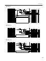
15
MIX buses 1–8
MIX buses 9–12
MIX buses 13–16
(SUB)(ST)
from INPUT
MIX 3-4, 5-6, 7-8: Same as MIX 1-2
MIX 2: Same as MIX 1
to Meter
VARIABLE
FIX
AFL
PFL
LRON
MAS
AFL
MAS
(MIX)
TO MATRIX
CONTROL
ONCHECK
ON/EDIT
MIX OUT 1
AFL
TO STEREO
PAN
TO MATRIX
MIX
INSERT
I/O
ST
RL
LR
MIX
(FIX)
MIX
(VARIABLE)
1 3 5 7 12345678
2468
9 111315
10 12 14 16
from Ctrl
Master
1357
2468
9 111315
10 12 14 16
LR
LR
(SUB)(ST)
AFL
PFL
LRON
MAS
AFL
MAS
(MIX)
TO MATRIX
ST
RL
LR
MIX
(FIX)
MIX
(VARIABLE)
1 3 5 7 12345678
2468
9 111315
10 12 14 16
1357
2468
9111315
10 12 14 16
LR
LR
from ST CH
from Ctrl Master
ON/EDIT
CHECK ON
CONTROL
MIX 10, 11, 12: Same as MIX 9
to Meter
TO MATRIX
PAN
TO STEREO
AFL
MIX OUT 9
MIX
INSERT
I/O
(SUB)(ST)
AFL
PFL
LRON
MAS
AFL
MAS
(MIX)
TO MATRIX
ST
RL
LR
MIX
(FIX)
MIX
(VARIABLE)
1 3 5 7 12345678
2468
9 111315
10 12 14 16
1357
2468
9111315
10 12 14 16
LR
LR
from Ctrl Master
CONTROL
ONCHECK
ON/EDIT
MIX 15-16: Same as MIX 13-14
to Meter
AFL
TO MATRIX
BAL
TO STEREO
MIX OUT 14
MIX
INSERT
I/O
MIX
INSERT
I/O
MIX OUT 13

Control panel
16
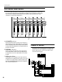
VCA master fader section
The VCA master fader section allows the gain of input channels assigned to a VCA group to
be controlled as a whole by the corresponding VCA fader. The VCA group(s) to which each
input channel is assigned is specified by the VCA GROUP select switches (mono input
channels (U), stereo input channels R).
A VCA MUTE switches
When these switches are turned on (the indicator at
left will light), the VCA master fader (3) will be shut
down completely. At this time, the post-fader signal of
all input channels assigned to the corresponding VCA
group will be muted.
B NOMINAL indicators
These indicators will light when the corresponding
VCA master fader is in the nominal (0 dB) position.
In this position, the VCA master fader will not affect
the gain.
C VCA master faders
These faders control the gain of the input channels
assigned to the corresponding VCA group. If you wish
to use the VCA master faders, make sure that the rear
panel VCA MASTER/SLAVE select switch (page 28) is
set to the MASTER position.
STEREO A section
This section controls the signal that is output from the
rear panel ST OUT jacks (page 28). The signal level
which is sent from ST OUT A to the matrix is also
controlled by this section.
MIX 13/14MIX 11/12 MIX 15/16
NOMINALNOMINAL
VCA
MUTE
VCA
MUTE
5
0
5
10
20
30
40
50
60
10
5
0
5
10
20
30
40
50
60
10
NOMINAL
VCA
MUTE
5
0
5
10
20
30
40
50
60
10
MIX 9/10
NOMINAL
VCA
MUTE
5
0
5
10
20
30
40
50
60
10
MIX 7/8
NOMINAL
VCA
MUTE
5
0
5
10
20
30
40
50
60
10
MIX 5/6
NOMINAL
VCA
MUTE
5
0
5
10
20
30
40
50
60
10
MIX 3/4
NOMINAL
VCA
MUTE
5
0
5
10
20
30
40
50
60
10
MIX 1/2
NOMINAL
VCA
MUTE
5
0
5
10
20
30
40
50
60
10
A
B
C
(SUB)(ST)
ON
ON/EDIT
CHECK ON
CONTROL
to Meter
to Meter
ON
AFL
AFL
TO MATRIX
AFL
PFL
LRON
MAS
AFL
MAS
LR
PFL
(MIX)
TO MATRIX
LEVEL
ST OUT B
L
R
ST
INSERT
I/O L
ST
INSERT
I/O R
R
L
ST OUT A
ST
RL
LR
1357
2468
9 111315
10 12 14 16
LR
LR
to MONITOR OUT
to PHONES

Control panel
17
A TO MATRIX switch
When this switch is on ( ), the ST OUT A post-
fader signal is sent to the matrix.
B ON/EDIT switch
The function of this switch and indicator will depend
on the mode of the M3000.
●In normal mode
The ON/EDIT switch will turn ST OUT A on/off.
When on, the ON indicator will light. When off, no
signal will be sent to the ST OUT A jacks, MONITOR
OUT jacks, PHONES jack, MAS AFL bus, or the
matrix. However even in this case, you can turn on the
AFL switch (3) to monitor the pre-fader signal from
the MONITOR OUT jacks or the PHONE jack.
●In check mode
You can use the CHECK indicator to view the on/off
status of ST OUT A stored in a scene before you actu-
ally recall the scene.
In check mode, you can also use the ON/EDIT switch
to change only the lit/dark status of the CHECK indi-
cator. (The actual on/off setting will not be affected.)
C AFL switch
This switch allows the ST OUT A signal which is sent
to the ST OUT A jacks or to the matrix to be moni-
tored from the MONITOR OUT jacks or from the
PHONES jack. When this switch is on ( ), the pre-
fader signal will be sent to the MAS PFL bus and the
post-fader signal will be sent to the MAS AFL bus,
allowing you to monitor them from the MONITOR
OUT jacks or the PHONES jack.
When the master section MASTER PFL switch
(page 19) is off you can monitor the signal of the MAS
AFL bus, and when it is on you can monitor the signal
of the MAS PFL bus. However if even one of the PFL
switches of the input channels is turned on, the signal
of the PFL bus will take priority for monitoring, and it
will not be possible to monitor ST OUT A.
D ST (stereo) fader
This fader adjusts the final output level of ST OUT A.
This fader affects the level of the signal which is sent
to the ST OUT A jacks, the MONITOR OUT jacks,
the PHONES jack, the MAS AFL bus, and the matrix.
10
5
0
5
10
20
30
40
50
60
STEREO A
TO MATRIX
ON/EDIT
AFL
CHECK
ON
STEREO A
A
D
C
B

Control panel
18
STEREO B section
This section controls the signal which is output from
the rear panel ST OUT B jacks (page 28)
A LEVEL control
This controls the output level of the signal which is
sent from the ST OUT B jacks. It does not affect the
signal which is output from the ST OUT A jacks.
When the control is in the “▲” position the level is
nominal (0 dB).
B ON switch
This is an on/off switch for the signal which is output
from the ST OUT B jacks. It does not affect the signal
which is output from the ST OUT A jacks. When this
switch is turned off, the indicator will go dark, and no
signal will be output from the ST OUT B jacks. How-
ever even in this case, the signal sourced before pass-
ing through the LEVEL control can be monitored
from the MONITOR OUT jacks or the PHONES jack
by turning on the AFL switch (3).
C AFL switch
This switch allows the signal which is sent from the ST
OUT B jacks to be monitored from the MONITOR
OUT jacks or PHONES jack. When this switch is on
( ) the signal before passing through the LEVEL
control will be sent to the MAS PFL bus and the signal
after passing through the LEVEL control will be sent
to the MAS AFL bus, and can be monitored from the
MONITOR OUT jacks or the PHONES jack.
If the master section MASTER PFL switch (page 19) is
off, the MAS AFL bus signal can be monitored. If this
switch is on, the MAS PFL bus signal will be moni-
tored. However if even one of the input channel PFL
switches are on, the PFL bus signal will take priority
for monitoring, and ST OUT B cannot be monitored.
Note: This section is not affected by the on/off
switching of scene memory.
STEREO B
ON
AFL
LEVEL
100
A
C
B
(SUB)(ST)
to Meter
ON
ON/EDIT
CHECK ON
CONTROL
ON
from
STEREO B R
CUE R
STEREO B L
CUE L
from
to Meter
to Meter
INPUT
MASTER
ON
L+R
ON
BA
BA
BA
BA
Phon
e
PHONES
2TR IN
2
1
1/2
BA
BA
BA
BA
L
R
L
R
MASTER PFL
LEVEL
L
R
MON
I
OUT
AFL
AFL
TO MATRIX
AFL
PFL
LRON
MAS
AFL
MAS
LR
PFL
(MIX)
TO MATRIX
LEVEL
ST OUT B
L
R
ST
INSERT
I/O L
ST
INSERT
I/O R
R
L
ST OUT A
ST
RL
LR
STEREO B/CUE L
STEREO B/CUE R
1357
2468
9 111315
10 12 14 16
LR
LR

Control panel
19
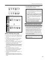
Monitor section
In this section you can select the signal which will be
monitored from the MONITOR OUT jacks and the
PHONES jack. The following signals can be selected
as monitor sources. Signal sources in priority group 1
can be selected at any time, and signal sources in pri-
ority group 2 can be selected only when no signal in
group 1 is selected.
Signals which can be selected as monitor
sources
A INPUT indicator
This indicator will light if even one of the input chan-
nel PFL switches are turned on.
B MASTER indicator
This indicator will light if even one of the AFL
switches of the mix section, STEREO A section, STE-
REO B section, or matrix section (page 24) are turned
on.
C MASTER PFL switch
This switch selects the master signal (the signal of
either the MAS AFL bus or the MAS PFL bus) which
will be monitored by the MONITOR jacks or
PHONES jack. When the MASTER PFL switch is on
( ) the signal of the MAS PFL bus will be moni-
tored. When this switch is off ( ), the signal of the
MAS AFL bus will be monitored.
D L+R switch
When this switch is on ( ), the monitor signal which
is output from the MONITOR OUT jacks and the
PHONES jack will be mixed to a monaural signal.
E 1/ 2 select switch
This switches between the two sets of 2TR IN jacks
located on the rear panel. When the switch is in the
upward position ( ) the 2TR IN 1 jacks are selected,
and when the switch is in the downward position
( ) the 2TR IN 2 jacks are selected.
F ON switch
This switch sends the input signal from the set of 2TR
IN jacks selected by the 1/2 select switch to the MON-
ITOR jacks and PHONES jack. When this switch is
pressed ( ), the input signal from the selected pair
of 2TR IN jacks will be sent to the MONITOR jacks
and PHONES jack.
Priority group 1
(can be selected at any time)
Priority group 2
(can be selected only when no
source of group 1 is selected)
• Mono input PFL
• Stereo input PFL
• MIX AFL
• ST bus (ST OUT A/B) AFL
• MATRIX AFL
• St OUT a
• 2TR IN
L+R
MASTER
PFL
2
1/
ON
INPUT
MASTER
2TR IN
C
D
E
F
A
B

Control panel
20
G LEVEL control
This control adjusts the level of the signal which is
output from the MONITOR OUT jacks. It does not
affect the PHONES jack.
H ON switch
This is an on/off switch for the signal which is output
from the MONITOR OUT jacks. When this is on, the
indicator located above the switch will light. This
switch does not affect the PHONES jack.
I PHONES (headphone) control
This control adjusts the level of the signal which is
output from the PHONES jack. It does not affect the
MONITOR OUT jacks.
J PHONES jack
A set of headphones can be connected to this jack for
monitoring.
PHONES
MONITOR
ON
100
LEVEL
100
G
I
J
H
to Meter
ON
ON/EDIT
CHECK ON
CONTROL
ON
from
STEREO B R
CUE R
STEREO B L
CUE L
from
to Meter
INPUT
MASTER
L+R
ON
BA
BA
BA
BA
Phones
PHONES
2TR IN
2
1
1/2
BA
BA
BA
BA
L
R
L
R
MASTER PFL
LEVEL
L
R
MONITOR
OUT
AFL
PFL
LRON
MAS
AFL
MAS
LR
PFL
ST
INSERT
I/O L
ST
INSERT
I/O R
R
L
ST OUT A
ST
RL
LR
STEREO B/CUE L
STEREO B/CUE R
Sidan laddas ...
Sidan laddas ...
Sidan laddas ...
Sidan laddas ...
Sidan laddas ...
Sidan laddas ...
Sidan laddas ...
Sidan laddas ...
Sidan laddas ...
Sidan laddas ...
Sidan laddas ...
Sidan laddas ...
Sidan laddas ...
Sidan laddas ...
Sidan laddas ...
Sidan laddas ...
Sidan laddas ...
Sidan laddas ...
Sidan laddas ...
Sidan laddas ...
Sidan laddas ...
Sidan laddas ...
Sidan laddas ...
Sidan laddas ...
Sidan laddas ...
Sidan laddas ...
Sidan laddas ...
Sidan laddas ...
-
 1
1
-
 2
2
-
 3
3
-
 4
4
-
 5
5
-
 6
6
-
 7
7
-
 8
8
-
 9
9
-
 10
10
-
 11
11
-
 12
12
-
 13
13
-
 14
14
-
 15
15
-
 16
16
-
 17
17
-
 18
18
-
 19
19
-
 20
20
-
 21
21
-
 22
22
-
 23
23
-
 24
24
-
 25
25
-
 26
26
-
 27
27
-
 28
28
-
 29
29
-
 30
30
-
 31
31
-
 32
32
-
 33
33
-
 34
34
-
 35
35
-
 36
36
-
 37
37
-
 38
38
-
 39
39
-
 40
40
-
 41
41
-
 42
42
-
 43
43
-
 44
44
-
 45
45
-
 46
46
-
 47
47
-
 48
48


Yamaha 40C Användarmanual
- Kategori
- Ljudmixer
- Typ
- Användarmanual
på andra språk
- italiano: Yamaha 40C Manuale utente
- čeština: Yamaha 40C Uživatelský manuál
- español: Yamaha 40C Manual de usuario
- Deutsch: Yamaha 40C Benutzerhandbuch
- polski: Yamaha 40C Instrukcja obsługi
- português: Yamaha 40C Manual do usuário
- français: Yamaha 40C Manuel utilisateur
- 日本語: Yamaha 40C ユーザーマニュアル
- Türkçe: Yamaha 40C Kullanım kılavuzu
- English: Yamaha 40C User manual
- dansk: Yamaha 40C Brugermanual
- русский: Yamaha 40C Руководство пользователя
- Nederlands: Yamaha 40C Handleiding
- română: Yamaha 40C Manual de utilizare