
GA5080
GA5080R
EN Angle Grinder INSTRUCTION MANUAL 7
SV Vinkelslipmaskin BRUKSANVISNING 15
NO Vinkelsliper BRUKSANVISNING 23
FI Kulmahiomakone KÄYTTÖOHJE 31
DA Vinkelsliber BRUGSANVISNING 39
LV Leņķa slīpmašīna LIETOŠANAS INSTRUKCIJA 47
LT Kampinis šlifuoklis NAUDOJIMO INSTRUKCIJA 55
ET Nurklihvkäi KASUTUSJUHEND 63
RU Угловая шлифмашина РУКОВОДСТВО ПО
ЭКСПЛУАТАЦИИ 71

1
Fig.1
1
Fig.2
1
Fig.3
Fig.4
3
2
1
Fig.5
2
B
1
A
B
Fig.6
2

2
1
A
C
C
Fig.7
1
2
Fig.8
1
2
Fig.9
1
Fig.10
1
2
Fig.11
1
2
A
B
Fig.12
3

4
3
1
2
Fig.13
1
2
Fig.14
1
A
B
Fig.15
1
Fig.16
1
Fig.17
1
Fig.18
1
2
Fig.19
4

15°
Fig.20
Fig.21
Fig.22
Fig.23
Fig.24
12
Fig.25
5

1
22 3
45
6
77
8
Fig.26
6

7ENGLISH
ENGLISH (Original instructions)
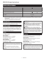
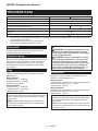
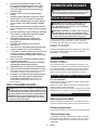
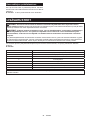
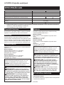
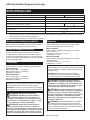
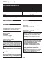
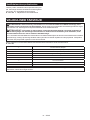
SPECIFICATIONS
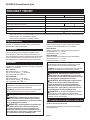
Model: GA5080 GA5080R
Wheel diameter 125 mm
Max. wheel thickness 6 mm
Rated speed (RPM) 12,000 min-1
Accidental re-start preventive function -
Overall length 309 mm
Net weight 2.5 - 3.6 kg
Safety class /II
• Duetoourcontinuingprogramofresearchanddevelopment,thespecicationshereinaresubjecttochange
without notice.
• Specicationsmaydierfromcountrytocountry.
• Weight according to EPTA-Procedure 01/2014
Intended use
The tool is intended for grinding and cutting of metal
and stone materials without the use of water.
Power supply
Thetoolshouldbeconnectedonlytoapowersupplyof
the same voltage as indicated on the nameplate, and
canonlybeoperatedonsingle-phaseACsupply.They
aredouble-insulatedandcan,therefore,alsobeused
from sockets without earth wire.
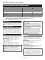
Noise
The typical A-weighted noise level determined accord-
ing to EN60745-2-3:
Model GA5080
Sound pressure level (LpA) : 84 dB(A)
Sound power level (LWA) : 95 dB (A)
Uncertainty (K) : 3 dB(A)
Model GA5080R
Sound pressure level (LpA) : 84 dB(A)
Sound power level (LWA) : 95 dB (A)
Uncertainty (K) : 3 dB(A)
NOTE: The declared noise emission value(s) has
beenmeasuredinaccordancewithastandardtest
methodandmaybeusedforcomparingonetoolwith
another.
NOTE: The declared noise emission value(s)
mayalsobeusedinapreliminaryassessmentof
exposure.
WARNING: Wear ear protection.
WARNING: The noise emission during actual
use of the power tool can dier from the declared
value(s) depending on the ways in which the
tool is used especially what kind of workpiece is
processed.
WARNING: Be sure to identify safety mea-
sures to protect the operator that are based on an
estimation of exposure in the actual conditions of
use (taking account of all parts of the operating
cycle such as the times when the tool is switched
o and when it is running idle in addition to the
trigger time).
Vibration
Thevibrationtotalvalue(tri-axialvectorsum)deter-
mined according to EN60745-2-3:
Model GA5080
Work mode: surface grinding with normal side grip
Vibrationemission(ah, AG) : 7.9 m/s2
Uncertainty (K) : 1.5 m/s2
Model GA5080R
Work mode: surface grinding with normal side grip
Vibrationemission(ah, AG) : 7.9 m/s2
Uncertainty (K) : 1.5 m/s2
NOTE:Thedeclaredvibrationtotalvalue(s)hasbeen
measured in accordance with a standard test method
andmaybeusedforcomparingonetoolwithanother.
NOTE:Thedeclaredvibrationtotalvalue(s)mayalso
beusedinapreliminaryassessmentofexposure.

8ENGLISH
WARNING: The vibration emission during
actual use of the power tool can dier from the
declared value(s) depending on the ways in which
the tool is used especially what kind of workpiece
is processed.
WARNING: Be sure to identify safety mea-
sures to protect the operator that are based on an
estimation of exposure in the actual conditions of
use (taking account of all parts of the operating
cycle such as the times when the tool is switched
o and when it is running idle in addition to the
trigger time).
WARNING:Thedeclaredvibrationemission
value is used for main applications of the power tool.
However if the power tool is used for other applica-
tions,thevibrationemissionvaluemaybedierent.
EC Declaration of Conformity
For European countries only
TheECdeclarationofconformityisincludedasAnnexA
to this instruction manual.
SAFETY WARNINGS
General power tool safety warnings
WARNING: Read all safety warnings, instruc-
tions, illustrations and specications provided
with this power tool. Failure to follow all instructions
listedbelowmayresultinelectricshock,reand/or
seriousinjury.
Save all warnings and instruc-
tions for future reference.
The term "power tool" in the warnings refers to your
mains-operated(corded)powertoolorbattery-operated
(cordless) power tool.
Grinder safety warnings
Safety Warnings Common for Grinding, Wire
Brushing, or Abrasive Cutting-O Operations:
1. This power tool is intended to function as a
grinder, wire brush or cut-o tool. Read all
safety warnings, instructions, illustrations and
specications provided with this power tool.
Failuretofollowallinstructionslistedbelowmay
resultinelectricshock,reand/orseriousinjury.
2. Operations such as sanding or polishing are
not recommended to be performed with this
power tool. Operations for which the power tool
was not designed may create a hazard and cause
personalinjury.
3. Do not use accessories which are not speci-
cally designed and recommended by the tool
manufacturer.Justbecausetheaccessorycan
beattachedtoyourpowertool,itdoesnotassure
safe operation.
4. The rated speed of the accessory must be at
least equal to the maximum speed marked on
the power tool. Accessories running faster than
theirratedspeedcanbreakandyapart.
5. The outside diameter and the thickness of your
accessory must be within the capacity rating
of your power tool. Incorrectly sized accessories
cannotbeadequatelyguardedorcontrolled.
6. Threaded mounting of accessories must
match the grinder spindle thread. For acces-
sories mounted by anges, the arbour hole of
the accessory must t the locating diameter
of the ange. Accessories that do not match the
mounting hardware of the power tool will run out of
balance,vibrateexcessivelyandmaycauseloss
of control.
7. Do not use a damaged accessory. Before each
use inspect the accessory such as abrasive
wheels for chips and cracks, backing pad for
cracks, tear or excess wear, wire brush for
loose or cracked wires. If power tool or acces-
sory is dropped, inspect for damage or install
an undamaged accessory. After inspecting and
installing an accessory, position yourself and
bystanders away from the plane of the rotating
accessory and run the power tool at maximum
no-load speed for one minute. Damaged acces-
sorieswillnormallybreakapartduringthistest
time.
8. Wear personal protective equipment.
Depending on application, use face shield,
safety goggles or safety glasses. As appro-
priate, wear dust mask, hearing protectors,
gloves and workshop apron capable of stop-
ping small abrasive or workpiece fragments.
Theeyeprotectionmustbecapableofstopping
yingdebrisgeneratedbyvariousoperations.
Thedustmaskorrespiratormustbecapableof
ltratingparticlesgeneratedbyyouroperation.
Prolonged exposure to high intensity noise may
cause hearing loss.
9. Keep bystanders a safe distance away from
work area. Anyone entering the work area
must wear personal protective equipment.
Fragmentsofworkpieceorofabrokenaccessory
mayyawayandcauseinjurybeyondimmediate
area of operation.
10. Hold the power tool by insulated gripping
surfaces only, when performing an operation
where the cutting accessory may contact hid-
den wiring or its own cord.Cuttingaccessory
contacting a "live" wire may make exposed metal
parts of the power tool “live” and could give the
operator an electric shock.
11. Position the cord clear of the spinning acces-
sory.Ifyoulosecontrol,thecordmaybecutor
snaggedandyourhandorarmmaybepulledinto
the spinning accessory.
12. Never lay the power tool down until the acces-
sory has come to a complete stop. The spinning
accessorymaygrabthesurfaceandpullthe
power tool out of your control.
13. Do not run the power tool while carrying it at
your side. Accidental contact with the spinning
accessory could snag your clothing, pulling the
accessoryintoyourbody.

9ENGLISH
14. Regularly clean the power tool’s air vents. The
motor’s fan will draw the dust inside the housing
and excessive accumulation of powdered metal
may cause electrical hazards.
15. Do not operate the power tool near ammable
materials. Sparks could ignite these materials.
16. Do not use accessories that require liquid
coolants.Usingwaterorotherliquidcoolants
may result in electrocution or shock.
Kickback and Related Warnings
Kickbackisasuddenreactiontoapinchedorsnagged
rotatingwheel,backingpad,brushoranyotheracces-
sory. Pinching or snagging causes rapid stalling of the
rotating accessory which in turn causes the uncon-
trolledpowertooltobeforcedinthedirectionopposite
oftheaccessory’srotationatthepointofthebinding.
Forexample,ifanabrasivewheelissnaggedorpinched
bytheworkpiece,theedgeofthewheelthatisenteringinto
the pinch point can dig into the surface of the material caus-
ingthewheeltoclimboutorkickout.Thewheelmayeither
jumptowardorawayfromtheoperator,dependingon
direction of the wheel’s movement at the point of pinching.
Abrasivewheelsmayalsobreakundertheseconditions.
Kickbackistheresultofpowertoolmisuseand/or
incorrectoperatingproceduresorconditionsandcanbe
avoidedbytakingproperprecautionsasgivenbelow.
1. Maintain a rm grip on the power tool and
position your body and arm to allow you to
resist kickback forces. Always use auxiliary
handle, if provided, for maximum control over
kickback or torque reaction during start-up.
Theoperatorcancontroltorquereactionsorkick-
backforces,ifproperprecautionsaretaken.
2. Never place your hand near the rotating acces-
sory.Accessorymaykickbackoveryourhand.
3. Do not position your body in the area where
power tool will move if kickback occurs.
Kickbackwillpropelthetoolindirectionopposite
to the wheel’s movement at the point of snagging.
4. Use special care when working corners, sharp
edges etc. Avoid bouncing and snagging the
accessory.Corners,sharpedgesorbouncing
have a tendency to snag the rotating accessory
andcauselossofcontrolorkickback.
5. Do not attach a saw chain woodcarving blade
or toothed saw blade.Suchbladescreatefre-
quentkickbackandlossofcontrol.
Safety Warnings Specic for Grinding and Abrasive
Cutting-O Operations:
1. Use only wheel types that are recommended
for your power tool and the specic guard
designed for the selected wheel. Wheels for
whichthepowertoolwasnotdesignedcannotbe
adequatelyguardedandareunsafe.
2. The grinding surface of centre depressed
wheels must be mounted below the plane of
the guard lip. An improperly mounted wheel that
projectsthroughtheplaneoftheguardlipcannot
beadequatelyprotected.
3.
The guard must be securely attached to the
power tool and positioned for maximum safety,
so the least amount of wheel is exposed towards
the operator. The guard helps to protect the opera-
torfrombrokenwheelfragments,accidentalcontact
with wheel and sparks that could ignite clothing.
4. Wheels must be used only for recommended
applications. For example: do not grind with
the side of cut-o wheel.Abrasivecut-owheels
are intended for peripheral grinding, side forces
applied to these wheels may cause them to
shatter.
5. Always use undamaged wheel anges that are
of correct size and shape for your selected
wheel.Properwheelangessupportthewheel
thusreducingthepossibilityofwheelbreakage.
Flangesforcut-owheelsmaybedierentfrom
grindingwheelanges.
6. Do not use worn down wheels from larger
power tools. Wheel intended for larger power tool
isnotsuitableforthehigherspeedofasmaller
toolandmayburst.
Additional Safety Warnings Specic for Abrasive
Cutting-O Operations:
1. Do not “jam“ the cut-o wheel or apply exces-
sive pressure. Do not attempt to make an
excessive depth of cut. Overstressing the wheel
increasestheloadingandsusceptibilitytotwisting
orbindingofthewheelinthecutandthepossibil-
ityofkickbackorwheelbreakage.
2. Do not position your body in line with and
behind the rotating wheel. When the wheel, at
the point of operation, is moving away from your
body,thepossiblekickbackmaypropelthespin-
ning wheel and the power tool directly at you.
3. When wheel is binding or when interrupting
a cut for any reason, switch o the power
tool and hold the power tool motionless until
the wheel comes to a complete stop. Never
attempt to remove the cut-o wheel from the
cut while the wheel is in motion otherwise
kickback may occur. Investigate and take correc-
tiveactiontoeliminatethecauseofwheelbinding.
4. Do not restart the cutting operation in the
workpiece. Let the wheel reach full speed and
carefully re-enter the cut.Thewheelmaybind,
walkuporkickbackifthepowertoolisrestartedin
the workpiece.
5. Support panels or any oversized workpiece to
minimize the risk of wheel pinching and kick-
back. Large workpieces tend to sag under their
ownweight.Supportsmustbeplacedunderthe
workpiece near the line of cut and near the edge
oftheworkpieceonbothsidesofthewheel.
6. Use extra caution when making a “pocket cut”
into existing walls or other blind areas. The
protruding wheel may cut gas or water pipes, elec-
tricalwiringorobjectsthatcancausekickback.
Safety Warnings Specic for Wire Brushing
Operations:
1. Be aware that wire bristles are thrown by the
brush even during ordinary operation. Do not
overstress the wires by applying excessive
load to the brush.Thewirebristlescaneasily
penetrate light clothing and/or skin.
2. If the use of a guard is recommended for wire
brushing, do not allow any interference of the
wire wheel or brush with the guard. Wire wheel
orbrushmayexpandindiameterduetoworkload
and centrifugal forces.

10 ENGLISH
Additional Safety Warnings:
1. When using depressed centre grinding wheels,
be sure to use only berglass-reinforced
wheels.
2. NEVER USE Stone Cup type wheels with this
grinder. This grinder is not designed for these
types of wheels and the use of such a product
mayresultinseriouspersonalinjury.
3. Be careful not to damage the X-LOCK holder.
Damage to the parts could result in wheel
breakage.
4. Make sure the wheel is not contacting the
workpiece before the switch is turned on.
5. Before using the tool on an actual workpiece,
let it run for a while. Watch for vibration or
wobbling that could indicate poor installation
or a poorly balanced wheel.
6. Use the specied surface of the wheel to per-
form the grinding.
7. Do not leave the tool running. Operate the tool
only when hand-held.
8. Do not touch the workpiece immediately after
operation; it may be extremely hot and could
burn your skin.
9. Do not touch accessories immediately after
operation; it may be extremely hot and could
burn your skin.
10. Observe the instructions of the manufacturer
for correct mounting and use of wheels.
Handle and store wheels with care.
11. Do not use separate reducing bushings or
adaptors to adapt large hole abrasive wheels.
12. Check that the workpiece is properly
supported.
13. Pay attention that the wheel continues to
rotate after the tool is switched o.
14. If working place is extremely hot and humid,
or badly polluted by conductive dust, use a
short-circuit breaker (30 mA) to assure opera-
tor safety.
15. Do not use the tool on any materials contain-
ing asbestos.
16. When use cut-o wheel, always work with
the dust collecting wheel guard required by
domestic regulation.
17. Cutting discs must not be subjected to any
lateral pressure.
18. Do not use cloth work gloves during operation.
Fibersfromclothglovesmayenterthetool,which
causestoolbreakage.
19. Before operation, make sure that there is no
buried object such as electric pipe, water pipe
or gas pipe in the workpiece. Otherwise, it may
cause an electric shock, electrical leakage or gas
leak.
SAVE THESE INSTRUCTIONS.
WARNING: DO NOT let comfort or familiarity
with product (gained from repeated use) replace
strict adherence to safety rules for the subject
product. MISUSE or failure to follow the safety
rules stated in this instruction manual may cause
serious personal injury.
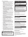
FUNCTIONAL DESCRIPTION
CAUTION: Always be sure that the tool is
switched o and unplugged before adjusting or
checking function on the tool.
Switch action
CAUTION: Before plugging in the tool, always
check to see that the slide switch actuates prop-
erly and returns to the "OFF" position when the
rear end of the slide switch is depressed.
CAUTION: Switch can be locked in the "ON"
position for ease of operator comfort during
extended use. Apply caution when locking tool in
the "ON" position and maintain rm grasp on tool.
To start the tool, press down the rear end of the slide
switch and then slide it toward the “I (ON)” position.
For continuous operation, press down the front end of
the slide switch to lock it.
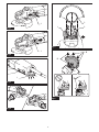
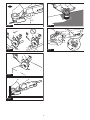
►Fig.1: 1. Slide switch
To stop the tool, press down the rear end of the slide
switch so that it returns to the “O (OFF)” position.
►Fig.2: 1. Slide switch
Indication lamp
Only for model GA5080R
►Fig.3: 1. Indication lamp
The indication lamp lights up green when the tool is plugged. If the
indication lamp does not light up, the mains cord or the controller
maybedefective.Theindicationlampislitbutthetooldoesnotstart
evenifthetoolisswitchedon,thecarbonbrushesmaybewornout,
orthecontroller,themotorortheON/OFFswitchmaybedefective.
Accidental re-start preventive function
Only for model GA5080R
Thetooldoesnotstartwiththeswitchbeinglock-on
even when the tool is plugged.
Atthistime,theindicationlampblinksredandshows
that the accidental re-start preventive function works.
To cancel the accidental re-start preventive function, return
the slide switch to "O (OFF)" position, then release it.
Electronic function
Constant speed control
Possibletogetnenish,becausetherotatingspeedis
kept constant even under the loaded condition.
Soft start feature
Soft start feature reduces starting reaction.
Overload protector
Whentheloadonthetoolexceedsadmissiblelevels,
power to the motor is reduced to protect the motor from
overheating.Whentheloadreturnstoadmissiblelev-
els, the tool will operate as normal.

11 ENGLISH
ASSEMBLY
CAUTION: Always be sure that the tool is
switched o and unplugged before carrying out
any work on the tool.
Installing side grip (handle)
CAUTION: Always be sure that the side grip is
installed securely before operation.
Screw the side grip securely on the position of the tool
asshowninthegure.
►Fig.4
Installing or removing wheel guard
WARNING: When using a depressed center
wheel or wire wheel brush, the wheel guard must
be tted on the tool so that the closed side of the
guard always points toward the operator.
WARNING: Make sure that the wheel guard is
securely locked by the lock lever with one of the
holes on the wheel guard.
WARNING: When using an abrasive cut-o
/ diamond wheel, be sure to use only the special
wheel guard designed for use with cut-o wheels.
(In some European countries, when using a diamond
wheel,theordinaryguardcanbeused.Followthe
regulations in your country.)
For depressed center wheel, wire
wheel brush / abrasive cut-o wheel,
diamond wheel
1. While pushing the lock lever, mount the wheel
guard with the protrusions on the wheel guard aligned
withthenotchesonthebearingbox.
►Fig.5: 1. Lock lever 2. Notch 3. Protrusion
2. While pushing the lock lever toward A, hold down
the portions B of the wheel guard as shown in the
gure.
►Fig.6: 1. Wheel guard 2. Hole
NOTE: Push down the wheel guard straight.
Otherwise, you cannot secure the wheel guard.
3. While pushing the lock lever toward A, rotate the
wheelguardtowardC,andthen,changetheangleof
the wheel guard according to the work so that the oper-
atorcanbeprotected.Alignthelockleverwithoneof
the holes in the wheel guard, and then release the lock
lever to lock the wheel guard.
►Fig.7: 1. Wheel guard 2. Hole
To remove wheel guard, follow the installation proce-
dure in reverse.
When using a depressed center
wheel
Optional accessory
WARNING: When using a depressed center
wheel, the wheel guard must be tted on the tool
so that the closed side of the guard always points
toward the operator.
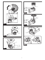
►Fig.8: 1. Depressed center wheel 2. Wheel guard
When using an abrasive cut-o /
diamond wheel
Optional accessory
WARNING: When using an abrasive cut-o
/ diamond wheel, be sure to use only the special
wheel guard designed for use with cut-o wheels.
(In some European countries, when using a diamond
wheel,theordinaryguardcanbeused.Followthe
regulations in your country.)
WARNING: NEVER use cut-o wheel for side
grinding.
►Fig.9: 1.Abrasivecut-owheel/diamondwheel
2.Wheelguardforabrasivecut-owheel/
diamond wheel
When using a wire cup brush
Optional accessory
CAUTION: Do not use wire cup brush that is
damaged, or which is out of balance. Use of dam-
agedbrushcouldincreasepotentialforinjuryfrom
contactwithbrokenbrushwires.
►Fig.10: 1.Wirecupbrush
When using a wire wheel brush
Optional accessory
CAUTION: Do not use wire wheel brush that
is damaged, or which is out of balance. Use of
damagedwirewheelbrushcouldincreasepotential
forinjuryfromcontactwithbrokenwires.
CAUTION: ALWAYS use guard with wire
wheel brushes, assuring diameter of wheel ts
inside guard. Wheel can shatter during use and
guardhelpstoreducechancesofpersonalinjury.
►Fig.11: 1.Wirewheelbrush2. Wheel guard

12 ENGLISH
Installing or removing X-LOCK wheel
WARNING: Never actuate the release lever of
the X-LOCK holder during operation. Make sure
that the X-LOCK wheel has stopped completely
when removing it.Otherwise,theX-LOCKwheel
comesofromthetoolandmaycauseseriousinjury.
CAUTION: Use only original X-LOCK wheels
with the X-LOCK logo. This tool is dedicated to
X-LOCK.
Themaximumclampinggaugeof1.6mmcanonlybe
guaranteedwithoriginalX-LOCKwheels.
Use of any other wheels may lead to insecure clamp-
ing, and cause the clamp tool to come loose.
CAUTION: Do not touch the X-LOCK wheel
immediately after operation.Itmaybeextremely
hotandcouldburnyourskin.
CAUTION: Make sure that the X-LOCK wheel
and holder of the tool are not deformed and are
free from dust or foreign matters.
CAUTION: Do not put your nger near the
holder while installing or removing the X-LOCK
wheel.Itmaypinchyournger.
CAUTION: Do not put your nger near the
release lever while installing the X-LOCK wheel. It
maypinchyournger.
NOTE:Noadditionalpartssuchasinneranges
orlocknutsarerequiredtoinstallorremovethe
X-LOCKwheels.
1. ToinstalltheX-LOCKwheel,makesurethatboth
catches are in the unlocked position.
If not, push the release lever from A side to lift B
side, then pull the release lever from B side as
illustrated. The catches are set in the unlocked
position.
►Fig.12: 1.Catch2. Release lever
2. PlaceacentralpositionoftheX-LOCKwheelon
the holder.
MakesuretheX-LOCKwheelisparalleltothe
angesurfaceandwiththecorrectsidefacingup.
3. PushtheX-LOCKwheelintotheholder.The
catches snap into the lock position with a click and
xtheX-LOCKwheel.
►Fig.13: 1.X-LOCKwheel2. Holder 3. Flange sur-
face 4.Catch
4. MakesuretheX-LOCKwheelisxedcorrectly.
ThesurfaceoftheX-LOCKwheelisnohigher
than the surface of the holder as shown in the
gure.
Ifnot,theholdermustbecleanedortheX-LOCK
wheelmustnotbeused.
►Fig.14: 1. Surface of the holder 2. Surface of the
X-LOCKwheel
ToremovetheX-LOCKwheel,pushthereleaselever
from A side to lift B side, then pull the release lever from
B side as illustrated.
TheX-LOCKwheelisreleasedandcanberemoved.
►Fig.15: 1. Release lever
Installing or removing dust cover
attachment
Optional accessory
CAUTION: Always be sure that the tool is
switched o and unplugged before installing or
removing the dust cover attachment. Failure to do
socausesdamagetothetoolorapersonalinjury.
There are three types of dust cover attachment and
eachisusedinoneofdierentpositions.
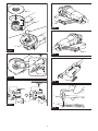
►Fig.16: 1. Marking A
►Fig.17: 1. Marking B
►Fig.18: 1.MarkingC
Place the dust cover attachment so that the side of the dust cover
attachmentwiththemarking(A,BorC)facestowardsthetool
head. Snap the hooks of the dust cover attachment in the vent.
►Fig.19: 1. Hook 2. Vent
Dustcoverattachmentcanberemovedbyhand.
NOTICE: Clean out the dust cover attachment
when it is clogged with dust or foreign matters.
Continuingoperationwithacloggeddustcover
attachment will damage the tool.
OPERATION
WARNING: It should never be necessary to
force the tool. The weight of the tool applies ade-
quatepressure.Forcingandexcessivepressure
couldcausedangerouswheelbreakage.
WARNING: ALWAYS replace wheel if tool is
dropped while grinding.
WARNING:
NEVER hit the workpiece with the wheel.
WARNING:
Avoid bouncing and snagging the
wheel, especially when working corners, sharp
edges etc.Thiscancauselossofcontrolandkickback.
WARNING: NEVER use tool with wood cutting
blades and other saw blades.Suchbladeswhen
usedonagrinderfrequentlykickandcauselossof
controlleadingtopersonalinjury.
WARNING:
Never actuate the release lever of
the X-LOCK holder during operation.AnX-LOCKwheel
comesofromthetoolandmaycauseseriousinjury.
WARNING: Make sure that an X-LOCK wheel
is xed rmly.
CAUTION:
Never switch on the tool when it is in con-
tact with the workpiece, it may cause an injury to operator.
CAUTION: Always wear safety goggles or a
face shield during operation.
CAUTION: After operation, always switch o
the tool and wait until the wheel has come to a
complete stop before putting the tool down.
CAUTION:
ALWAYS hold the tool rmly with one
hand on housing and the other on the side grip (handle).

13 ENGLISH
Grinding operation
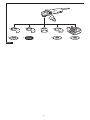
►Fig.20
Turn the tool on and then apply the wheel to the workpiece.
In general, keep the edge of the wheel at an angle of
about15°totheworkpiecesurface.
Duringthebreak-inperiodwithanewwheel,donot
work the grinder in forward direction or it may cut into
theworkpiece.Oncetheedgeofthewheelhasbeen
roundedobyuse,thewheelmaybeworkedinboth
forwardandbackwarddirection.
Operation with abrasive cut-o /
diamond wheel
Optional accessory
WARNING: Do not "jam" the wheel or apply
excessive pressure. Do not attempt to make an
excessive depth of cut. Overstressing the wheel
increasestheloadingandsusceptibilitytotwisting
orbindingofthewheelinthecutandthepossibility
ofkickback,wheelbreakageandoverheatingofthe
motor may occur.
WARNING: Do not start the cutting operation
in the workpiece. Let the wheel reach full speed
and carefully enter into the cut moving the tool
forward over the workpiece surface. The wheel
maybind,walkuporkickbackifthepowertoolis
started in the workpiece.
WARNING: During cutting operations, never
change the angle of the wheel. Placing side pres-
sureonthecut-owheel(asingrinding)willcause
thewheeltocrackandbreak,causingseriousper-
sonalinjury.
WARNING: A diamond wheel shall be oper-
ated perpendicular to the material being cut.
WARNING: NEVER use cut-o wheel for side
grinding.
Usage example: operation with abrasive cut-o
wheel
►Fig.21
Usage example: operation with diamond wheel
►Fig.22
Operation with wire wheel brush
Optional accessory
CAUTION: Check operation of wire wheel
brush by running tool with no load, insuring that
no one is in front of or in line with the wire wheel
brush.
CAUTION: Do not use wire wheel brush that
is damaged, or which is out of balance. Use of
damagedwirewheelbrushcouldincreasepotential
forinjuryfromcontactwithbrokenwires.
CAUTION: ALWAYS use wire wheel brushes
with the wheel guard, assuring diameter of wheel
ts inside the guard. Wheel can shatter during use
andguardhelpstoreducechancesofpersonalinjury.
NOTICE: Avoid applying too much pressure
which causes over bending of wires when
using wire wheel brush. It may lead to premature
breakage.
Usage example: operation with wire wheel brush
►Fig.23
Operation with wire cup brush
Optional accessory
CAUTION: Check operation of wire cup brush
by running tool with no load, insuring that no one
is in front of or in line with brush.
CAUTION: Do not use brush that is damaged,
or which is out of balance.Useofdamagedbrush
couldincreasepotentialforinjuryfromcontactwith
brokenbrushwires.
NOTICE: Avoid applying too much pressure
which causes over bending of wires when using
the wire cup brush. It may lead to premature
breakage.
Usage example: operation with wire cup brush
►Fig.24
MAINTENANCE
CAUTION: Always be sure that the tool is
switched o and unplugged before attempting to
perform inspection or maintenance.
NOTICE: Never use gasoline, benzine, thinner,
alcohol or the like. Discoloration, deformation or
cracks may result.
To maintain product SAFETY and RELIABILITY,
repairs,anyothermaintenanceoradjustmentshould
beperformedbyMakitaAuthorizedorFactoryService
Centers,alwaysusingMakitareplacementparts.
Air vent cleaning
Thetoolanditsairventshavetobekeptclean.
Regularly clean the tool's air vents or whenever the
ventsstarttobecomeobstructed.
►Fig.25: 1. Exhaust vent 2. Inhalation vent

14 ENGLISH
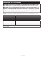
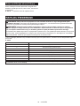
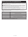
OPTIONAL ACCESSORIES
CAUTION: These accessories or attachments are recommended for use with your Makita tool spec-
ied in this manual.Theuseofanyotheraccessoriesorattachmentsmightpresentariskofinjurytopersons.
Only use accessory or attachment for its stated purpose.
CAUTION: Your tool is supplied with a guard for use with any recommended grinding wheel and wire
wheel brush. If a diamond wheel and/or cut-o wheel are also available for use with the tool, they should
only be used with the appropriate optional guard for cut-o wheels.
IfyoudecidetouseyourMakitagrinderwithapprovedaccessorieswhichyoupurchasefromyourMakitadistribu-
tororfactoryservicecenter,besuretoobtainanduseallnecessaryfastenersandguardsasrecommendedinthis
manual.Yourfailuretodosocouldresultinpersonalinjurytoyouandothers.
Ifyouneedanyassistanceformoredetailsregardingtheseaccessories,askyourlocalMakitaServiceCenter.
►Fig.26
1Vibrationproofgrip
2WheelGuard(forgrindingandbrushing)
3WheelGuard(forcut-owheel)
4Depressed center wheel
5Wirewheelbrush
6Wirecupbrush
7Abrasivecut-owheel/Diamondwheel
8Dust collecting wheel guard
-Dust cover attachment
NOTE:Someitemsinthelistmaybeincludedinthetoolpackageasstandardaccessories.Theymaydierfrom
country to country.

15 SVENSKA
SVENSKA (Originalinstruktioner)
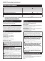
SPECIFIKATIONER
Modell: GA5080 GA5080R
Kapskivans diameter 125 mm
Max.skivtjocklek 6 mm
Nominellt varvtal (RPM) 12 000 min-1
Funktion för att förhindra oavsiktlig omstart -
Total längd 309 mm
Nettovikt 2,5 - 3,6 kg
Säkerhetsklass /II
• Pågrundavvårtpågåendeprogramförforskningochutvecklingkandessaspecikationerändrasutanföregå-
ende meddelande.
• Specikationerkanvarieramellanolikaländer.
• Vikt enligt EPTA-procedur 01/2014
Avsedd användning
Verktyget är avsett för slipning och skärning av metall-
och stenmaterial utan användning av vatten.
Strömförsörjning
Maskinen får endast anslutas till elnät med samma spänning
somangespåtypplåtenochmedenfasigväxelström.Deärdub-
belisoleradeochfårdärförocksåanslutasiojordadevägguttag.
Buller
DennormalabullernivånförA-belastningärbestämd
enligt EN60745-2-3:
Modell GA5080
Ljudtrycksnivå(LpA) : 84 dB (A)
Ljudeektnivå(LWA) : 95 dB (A)
Mättolerans (K): 3 dB (A)
Modell GA5080R
Ljudtrycksnivå(LpA) : 84 dB (A)
Ljudeektnivå(LWA) : 95 dB (A)
Mättolerans (K): 3 dB (A)
OBS:Detdeklareradebullervärdetharuppmättsi
enlighet med standardtestmetoden och kan användas
förjämförandetavenmaskinmedenannan.
OBS:
Detdeklareradebulleremissionsvärdetkanocksåanvän-
dasienpreliminärbedömningavexponeringförvibration.
VARNING: Använd hörselskydd.
VARNING:
Bulleremissionen under faktisk
användning av maskinen kan skilja sig från det dekla-
rerade värdet, beroende på hur maskinen används och
särskilt vilken typ av arbetsstycke som behandlas.
VARNING:
Var noga med att identiera säker-
hetsåtgärder för att skydda användaren, vilka är
grundade på en uppskattning av graden av exponering
för vibrationer under de faktiska användningsförhål-
landena, (ta, förutom avtryckartiden, med alla delar av
användarcykeln i beräkningen, som till exempel tiden
då maskinen är avstängd och när den går på tomgång).
Vibration
Dettotalavibrationsvärdet(treaxladvektorsumma)
bestämtenligtEN60745-2-3:
Modell GA5080
Arbetsläge:planslipningmednormaltsidohandtag
Vibrationsemission(ah, AG): 7,9 m/s2
Mättolerans (K): 1,5 m/s2
Modell GA5080R
Arbetsläge:planslipningmednormaltsidohandtag
Vibrationsemission(ah, AG): 7,9 m/s2
Mättolerans (K): 1,5 m/s2
OBS:Detdeklareradetotalavibrationsvärdethar
uppmätts i enlighet med standardtestmetoden och
kananvändasförjämförandetavenmaskinmeden
annan.
OBS:Detdeklareradetotalavibrationsvärdetkan
ocksåanvändasienpreliminärbedömningavexpo-
neringförvibration.
VARNING: Vibrationsemissionen under fak-
tisk användning av maskinen kan skilja sig från
det deklarerade värdet, beroende på hur maski-
nen används och särskilt vilken typ av arbetss-
tycke som behandlas.
VARNING: Var noga med att identiera säker-
hetsåtgärder för att skydda användaren, vilka är
grundade på en uppskattning av graden av expo-
nering för vibrationer under de faktiska använd-
ningsförhållandena, (ta, förutom avtryckartiden,
med alla delar av användarcykeln i beräkningen,
som till exempel tiden då maskinen är avstängd
och när den går på tomgång).
VARNING:Detdeklareradevibrationsemis-
sionsvärdet används för maskinens huvudsakliga
arbetsuppgifter.Ommaskinenanvändsförandra
arbetsuppgifterkandäremotvibrationsemissionsvär-
detbliannorlunda.

16 SVENSKA
EG-försäkran om överensstämmelse
Gäller endast inom EU
EG-försäkran om överensstämmelse inkluderas som
bilagaAtilldennabruksanvisning.
SÄKERHETSVARNINGAR
Allmänna säkerhetsvarningar för
maskiner
VARNING: Läs alla säkerhetsvarningar, anvis-
ningar, illustrationer och specikationer som
medföljer det här maskinen.Underlåtenhetattfölja
instruktionernakanledatillelstötar,brandoch/eller
allvarliga personskador.
Spara alla varningar och instruk-
tioner för framtida referens.
Termen ”maskin” som anges i varningarna hänvisar till
dineldrivnamaskin(sladdansluten)ellerbatteridrivna
maskin (sladdlös).
Säkerhetsvarningar för slipmaskin
Gemensamma säkerhetsvarningar för slipning,
stålborstning eller abrasiv skärning:
1. Den här maskinen är utformad för att använ-
das för slipning, stålborstning eller som skär-
verktyg. Läs igenom alla säkerhetsvarningar,
anvisningar, illustrationer och specikationer
som medföljer detta verktyg. Underlåtenhet att
följainstruktionernakanledatillelstötar,brand
och/eller allvarliga personskador.
2. Den här maskinen rekommenderas inte
för sandpapprings- eller poleringsarbeten.
Omverktygetanvändstillandraarbetenän
de avsedda kan det orsaka fara och leda till
personskada.
3. Använd inte tillbehör som inte är särskilt till-
verkade och rekommenderade av maskinens
tillverkare.Ävenometttillbehörkanfästaspå
maskinen garanterar detta inte säker funktion.
4. Tillbehörets nominella varvtal måste vara
minst lika med det maximala varvtalet som
anges på verktyget.Tillbehörsomanvändsöver
det nominella varvtalet kan gå sönder och orsaka
skador.
5. Tillbehörets ytterdiameter och tjocklek måste
vara anpassad till elverktygets kapacitets-
klassning.Tillbehöriolämpligstorlekkaninte
skyddas eller styras tillräckligt väl.
6. Gängorna på tillbehör som monteras måste
stämma överens med spindelgängorna på
slipmaskinen. För tillbehör som monteras med
änsar måste tillbehörets centrumhål passa i
änsens lokaliseringsdiameter.Tillbehörsom
intepassarexaktpåmaskinensmonteringsbeslag
roterarojämnt,vibrerarkraftigtochkanledatillatt
du förlorar kontrollen.
7. Använd inte ett skadat tillbehör. Kontrollera
tillbehör som sliprondeller efter hack och
sprickor, underlagsplattor efter sprickor,
slitage och stålborstar efter lösa eller brutna
trådar. Om du tappar maskinen eller ett tillbe-
hör ska du kontrollera att det inte har uppstått
några skador, eller så ska tillbehöret bytas ut
mot ett oskadat. Efter kontroll och montering
av tillbehöret ska du och åskådare hålla er
borta från det roterande tillbehöret samtidigt
som du kör maskinen på full fart utan last i
en minut.Skadadetillbehörgårnormaltsönder
under den här testtiden.
8. Använd personlig skyddsutrustning. Använd
visir, korgglasögon eller skyddsglasögon
beroende på arbetsuppgift. Använd vid
behov dammskydd, hörselskydd, handskar
och skyddsförkläde som stoppar små bitar
slipmaterial eller fragment från arbetss-
tycket.Ögonskyddetmåstekunnastoppay-
gandefragmentsomuppstårvidolikaarbeten.
Dammskyddet eller andningsskyddet måste kunna
ltrerapartiklarsomuppstårvidolikaarbeten.
Långtidikraftigtbullerkanorsakahörselskador.
9. Håll personer i omgivningen på säkert avstånd
från arbetsområdet. Alla som benner sig
i arbetsområdet måste använda skyddsut-
rustning.Delaravarbetsstycketellerdefekta
tillbehörkanygaivägochorsakaskadorutanför
arbetsområdet.
10. Håll endast verktyget i de isolerade handtagen
när du utför arbete där verktyget kan komma i
kontakt med en dold elkabel eller med verkty-
gets kabel. Om kapmaskinen kommer i kontakt
medenströmförandeledningblirverktygets
blottlagdametalldelarströmförandeochkange
användaren en elektrisk stöt.
11. Placera nätsladden på avstånd från det rote-
rande tillbehöret. Om du förlorar kontrollen kan
nätsladden kapas eller fastna och din hand eller
arm kan dras in i det roterande verktyget.
12. Lägg aldrig elverktyget åt sidan förrän det har
stannat helt.Detroterandetillbehöretkangripa
tag i underlaget och du kan förlora kontrollen över
maskinen.
13. Kör inte verktyget samtidigt som du bär det.
Oavsiktligkontaktmeddetroterandetillbehöret
kan leda till att det fastnar i dina kläder och dras in
mot kroppen.
14. Rengör regelbundet verktygets ventilations-
öppningar.Motornsäktsugerindammihöljet
och överdriven ansamling av pulveriserad metall
kan orsaka elektrisk fara.
15. Använd inte verktyget i närheten av lättan-
tändliga material. Gnistor kan antända dessa
material.
16. Använd inte tillbehör som kräver ytande kyl-
vätskor.Attanvändavattenellerandraytande
kylvätskor kan orsaka dödsfall eller elektriska
stötar.

17 SVENSKA
Bakåtkast och relaterade varningar
Bakåtkast är en plötslig reaktion på fastnypt roterande
hjul,underlagsplatta,borsteellerannattillbehör.Nyp
ochkärvningorsakarstegringavdetroterandetillbehö-
ret, och orsakar i sin tur att den okontrollerade maski-
nen tvingas i motsatt riktning vid kärvningspunkten.
Om till exempel en slipskiva fastnar i eller kläms fast av
arbetsstycketkanskivanskapandekantgrävasigini
materialytan vid klämpunkten, vilket leder till att skivan
klättrarellerkastastillbaka.Skivankanantingenhoppa
motellerfrånanvändaren,beroendepåskivansrörel-
seriktning vid klämpunkten. Slipskivorna kan även gå
sönder under dessa omständigheter.
Bakåtkastberorpåovarsamhetoch/ellerfelaktiga
arbetsrutiner,ochkanundvikasgenomattvidtanedan-
ståendeförebyggandeåtgärder.
1. Se till att hålla verktyget i ett fast grepp och
placera kroppen och din arm på ett sätt som
gör att du kan stå emot kraften från bakåtkast.
Använd alltid ett extrahandtag, om sådant
nns, för maximal kontroll vid bakåtkast eller
vridrörelsen vid start. Användaren kan kontroll-
eravridrörelsenellerkrafternavidbakåtkastom
rätt försiktighetsåtgärder vidtas.
2.
Placera aldrig din hand nära det roterande tillbe-
höret.Tillbehöretkankastasbakåtöverdinhand.
3. Ställ dig inte där maskinen kommer att förytta
sig i händelse av bakåtkast. Bakåtkast driver
verktyget i motsatt riktning till kapskivans rörelse
vid kärvningspunkten.
4. Var extra försiktig när du bearbetar hörn,
vassa kanter osv. Undvik att studsa och stöta
tillbehöret. Hörn, skarpa kanter eller studsning
harentendensattklämmadetroterandetillbehö-
retochorsakaförloradkontrollellerbakåtkast.
5. Montera inte en sågkedja, snidarblad eller ett
tandat sågblad.Sådanabladorsakaroftabakåt-
kast och förlorad kontroll.
Säkerhetsvarningar för slipning och abrasiv skärning:
1. Använd endast de skivor som rekommenderas
för din maskin och det särskilda sprängskyd-
det för skivan. Skivor som inte tillverkats för
maskinen kan inte skyddas tillräckligt och är inte
tillförlitliga.
2. Slipytan på nedsänkta skivor måste monte-
ras under planet från sprängskyddets kant.
En felaktigt monterad skiva som sticker utanför
planet från sprängskyddets kant är inte tillräckligt
skyddad.
3. Sprängskyddet måste vara ordentligt fäst vid
maskinen och placerat för maximal säkerhet,
så att minsta möjliga yta av skivan är öppen
mot användare. Sprängskyddet skyddar använ-
daren mot trasiga skivdelar, oavsiktlig kontakt med
skivan och gnistor som kan antända kläder.
4. Kapskivorna får endast användas till rekom-
menderade arbetsuppgifter. Till exempel: Slipa
inte med en kapskivas utsida. Slipande kapski-
vor är avsedda för periferislipning. Sidokrafter kan
spränga sådana skivor.
5. Använd alltid oskadade skivänsar i rätt stor-
lek och form till din skiva.Rättskivänsarstöder
kapskivan och minskar därigenom risken för att
skivangårsönder.Flänsartillkapskivorkanskilja
sigfrånänsartillslipskivor.
6. Använd inte nedslitna skivor för större maski-
ner. Skivor avsedda för större maskiner är inte
lämpliga för mindre maskiners högre varvtal och
kan spricka.
Ytterligare särskilda säkerhetsvarningar för abrasiv
skärning:
1. ”Pressa” inte skivan eller utsätt den för över-
drivet tryck. Försök inte att göra ett alltför stort
kapdjup.Omkapskivanöverbelastasökarbelast-
ningen och risken för att skivan vrids eller fastnar i
kapetsamtriskenförbakåtkastellerattskivangår
sönder.
2. Placera inte din kropp längs med eller bakom
den roterande skivan. När skivan rör sig ifrån
dig,kanettbakåtkastskickadenroterandeskivan
och maskinen mot dig.
3. Om kapskivan kärvar eller om ett kap avbryts
stänger du av elverktyget och håller det stilla
tills skivan har stannat helt. Försök aldrig att ta
ut kapskivan ur skäret när skivan är i rörelse,
för att undvika bakåtkast. Undersök och vidta
korrigeringsåtgärder för att eliminera orsaken till
att kapskivan fastnar.
4. Starta inte om kapningen med verktyget kvar i
arbetsstycket. Låt maskinen nå full hastighet
och gå tillbaka i skäret. Kapskivan kan fastna,
vandrauppåtellerkastasbakåtomelverktyget
startasomiarbetsstycket.
5. Stötta långa eller stora arbetsstycken för att
minimera risken för att kapskivan fastnar
och kastas bakåt.Storaarbetsstyckentenderar
att svikta på grund av sin egen vikt. Stöd måste
placerasunderarbetsstycketnärasåglinjenoch
näraarbetsstycketskanterpåbådasidornaom
kapskivan.
6. Var extra försiktig vid genomstickssågning i
en bentlig vägg eller andra dolda utrymmen.
Denutskjutandekapskivankankapagas-eller
vattenledningar, elledningar eller föremål som kan
orsakabakåtkast.
Säkerhetsvarningar särskilt vid stålborstning:
1. Var uppmärksam på att trådbitar kastas ut
från borsten även vid normal användning.
Överbelasta inte trådarna genom att anlägga
onödigt stor kraft mot borsten. Trådarna kan
enkelt gå igenom tunnare klädsel och/eller huden.
2. Om användning av skydd rekommenderas
vid stålborstningfår inte borstskivan eller
borsten gå emot skyddet. Borstens diameter
kanexpanderapågrundavbelastningeneller
centrifugalkraften.
Ytterligare säkerhetsvarningar:
1. Vid användning av nedsänkta center-rondel-
ler ska endast glasberförstärkta rondeller
användas.
2. ANVÄND ALDRIG sten-skålskivor med denna
slipmaskin. Denna slipmaskin är inte konstrue-
rad för denna typ av skivor och användningen av
dessa kan resultera i allvarlig personskada.
3. Var noga med att inte skada X-LOCK-hållaren.
Skador på delarna kan medföra att rondellen
förstörs.

18 SVENSKA
4. Se till att rondellen inte är i kontakt med
arbetsstycket när du trycker på avtryckaren.
5. Låt verktyget vara igång en stund innan det
används på arbetsstycket. Kontrollera att ski-
van inte vibrerar eller skakar, vilket kan inne-
bära att den är felaktigt monterad eller dåligt
balanserad.
6. Slipa endast med den del av rondellen som är
avsedd för slipning.
7. Lämna inte maskinen igång. Använd endast
maskinen när du håller den i händerna.
8. Rör inte vid arbetsstycket omedelbart efter
arbetet. Det kan vara extremt varmt och orsaka
brännskador.
9. Rör inte vid tillbehör omedelbart efter arbe-
tet. Det kan vara extremt varmt och orsaka
brännskador.
10. Följ tillverkarens anvisningar för korrekt mon-
tering och användning av rondeller. Hantera
rondellerna varsamt och förvara dem på en
säker plats.
11. Använd inte separata reducerhylsor eller adap-
trar för att kunna använda sliprondeller med
större hål.
12. Kontrollera att arbetsstycket är ordentligt
fastsatt.
13. Tänk på att rondellen fortsätter att rotera efter
att maskinen stängts av.
14. Om arbetsplatsen är extremt varm och fuk-
tig, eller har hög koncentration av elektriskt
ledande damm, ska jordfelsbrytare (30 mA)
användas för användarens säkerhet.
15. Använd inte maskinen för material som
innehåller asbest.
16. Använd alltid föreskrivet dammuppsamlande
sprängskydd när du arbetar med kapskiva.
17. Kapskivor får inte utsättas för sidokrafter.
18. Använd inte arbetshandskar i tyg när du arbe-
tar med maskinen.Fibrerfråntyghandskarkan
komma in i maskinen och orsaka fel.
19. Innan användning måste du se till att det inte
nns några begravda föremål som elrör, vat-
tenrör eller gasrör i arbetsstycket. Annars kan
det orsaka elstöt, elektriskt läckage eller gasläcka.
SPARA DESSA ANVISNINGAR.
VARNING: GLÖM INTE att också fortsätt-
ningsvis strikt följa säkerhetsanvisningarna för
maskinen även efter att du blivit van att använda
den. Vid FELAKTIG HANTERING av maskinen
eller om inte säkerhetsanvisningarna i denna
bruksanvisning följs kan följden bli allvarliga
personskador.
FUNKTIONSBESKRIVNING
FÖRSIKTIGT: Se alltid till att maskinen är
avstängd och nätsladden urdragen innan du jus-
terar eller funktionskontrollerar maskinen.
Avtryckarens funktion
FÖRSIKTIGT:
Innan du ansluter verktyget till elnätet
ska du kontrollera att skjutreglaget fungerar och återgår till
läget ”OFF” när du trycker på den bakre delen av knappen.
FÖRSIKTIGT:
Knappen kan låsas i läget ”ON” för
att underlätta användning när verktyget används under en
längre tid. Iaktta försiktighet när du låser verktyget i läget
”ON” och fortsätt att hålla ett stadigt grepp om verktyget.
Startaverktygetgenomatttryckanerskjutreglagets
bakändeochsedanskjutadenmotläget”I(PÅ)”.
Föroavbrutenkörningtryckerdupåskjutreglagets
framändesådetblirlåst.
►Fig.1: 1.Skjutknapp
Stoppaverktygetgenomatttryckapåskjutreglagets
bakändesåattdetåtergårtillläget”O(AV)”.
►Fig.2: 1.Skjutreglage
Indikatorlampa
Endast för modell GA5080R
►Fig.3: 1. Indikatorlampa
Den gröna indikatorlampan lyser när verktyget är inkopplat.
Om indikatorlampan inte tänds kan nätsladden eller styr-
ningen vara defekt. Om indikatorlampan lyser och verktyget
intestartarfaständetärpåslaget,kankolborstarnavara
utslitna,ellerstyrningen,motornellerströmbrytarendefekta.
Funktion för att förhindra oavsiktlig
omstart
Endast för modell GA5080R
Verktyget startar inte när avtryckaren är i låst läge även
om den är ansluten till elnätet.
Idettalägeblinkarindikatorlampanröttförattvisaatt
startspärrfunktionen fungerar.
Förattbrytaspärrenmotoavsiktligomstartskaskjutregla-
getförastillbakatillläget”O(OFF)”,ochdäreftersläppas.
Elektronisk funktion
Konstant hastighetskontroll
Detärmöjligtattfåennnisheftersomrotationshas-
tighetenhållskonstantävenvidhögbelastning.
Mjukstartfunktion
Mjukstartfunktionendämparstartchocken.
Överbelastningsskydd
Närbelastningenpåverktygetöverstigerdentillåtna
nivån, minskar strömmen till motorn för att skydda
motornfrånattöverhettas.Närbelastningenåtergårtill
den normala fungerar verktyget som vanligt.

19 SVENSKA
MONTERING
FÖRSIKTIGT: Se alltid till att maskinen är
avstängd och nätsladden urdragen innan maski-
nen repareras.
Montera sidohandtaget
FÖRSIKTIGT: Kontrollera alltid att sidohand-
taget sitter fast ordentligt innan arbetet påbörjas.
Skruva fast sidhandtaget ordentligt på rätt plats på
maskinenenligtguren.
►Fig.4
Montera eller demontera
sprängskyddet
VARNING: När en sliprondell med försänkt
navrondell eller skivstålborste används måste
sprängskyddet monteras på verktyget så att den
slutna sidan alltid är vänd mot användaren.
VARNING: Se till att sprängskyddet är
ordentligt låst med låsspaken med ett av hålen i
sprängskyddet.
VARNING: Vid användning av en kap-/
diamantskiva ska du vara noga med att endast
använda det speciella sprängskydd som är avsett
för användning tillsammans med kapskivor.
(I vissa europeiska länder kan det vanliga sprängs-
kyddet användas tillsammans med diamantskivan.
Följföreskrifternaidittland.)
För rondell med försänkt
navrondell, skivstålborste/kapskiva,
diamantskiva
1. När du trycker på låsspaken monterar du sprängs-
kyddetsåattdeutskjutandedelarnapåsprängskyddets
bandpassariniuttagenpålagerhuset.
►Fig.5: 1. Låsspak 2. Skåra 3. Utsprång
2. Tryck in låsspaken mot A och håll samtidigt ner
delarnaBpåsprängskyddetenligtbilden.
►Fig.6: 1. Sprängskydd 2. Hål
OBS: Tryck sprängskyddet rakt ner. I annat fall kan
du inte trycka ner sprängskyddet helt.
3. Medan du trycker låsspaken mot A vrider du
sprängskyddetmotC,ochdärefterändrarduvinkelnpå
sprängskyddetienlighetmedarbetsstycketsådetblir
skydd för operatören. Passa in låsspaken med ett av
hålen i sprängskyddet, och lossa sedan låsspaken för
att låsa sprängskyddet.
►Fig.7: 1. Sprängskydd 2. Hål
Görpåomväntsättföratttabortsprängskyddet.
När en rondell med försänkt
navrondell används
Valfria tillbehör
VARNING: Vid användning av en rondell med
försänkt navrondell måste sprängskyddet mon-
teras på verktyget så att skyddets stängda sida
alltid pekar mot användaren.
►Fig.8: 1. Försänkt navrondell 2. Sprängskydd
När en kap-/diamantskiva används
Valfria tillbehör
VARNING: Vid användning av en kap-/
diamantskiva ska du vara noga med att endast
använda det speciella sprängskydd som är avsett
för användning tillsammans med kapskivor.
(I vissa europeiska länder kan det vanliga sprängs-
kyddet användas tillsammans med diamantskivan.
Följföreskrifternaidittland.)
VARNING: Använd ALDRIG kapskivor för
sidoslipning.
►Fig.9: 1. Kap-/diamantskiva 2. Sprängskydd för
kap-/diamantskiva
Installation av skålformad stålborste
Valfria tillbehör
FÖRSIKTIGT: Använd inte en skålformad
stålborste som är skadad eller obalanserad.
Användningavenskadadborstekanökariskenför
skadorpågrundavkontaktmedtrasigaborsttrådar.
►Fig.10: 1.Skålformadstålborste
Installation av skivstålborste
Valfria tillbehör
FÖRSIKTIGT: Använd inte en skivstålborste
som är skadad eller obalanserad. Användning av
enskadadskivstålborstekanökariskenförskadorpå
grundavkontaktmedtrasigaborsttrådar.
FÖRSIKTIGT: Använd ALLTID skydd tillsam-
mans med skivstålborstar och kontrollera att
skivdiametern passar innanför skyddet. Skivan
kan splittras under användningen och skyddet mins-
kar risken för personskador.
►Fig.11: 1.Skivstålborste2. Sprängskydd

20 SVENSKA
Installera eller ta bort
X-LOCK-rondell
VARNING: Lös aldrig ut X-LOCK-hållarens
frigöringsspak under användning. Se till att
X-LOCK-rondellen har stannat fullständigt när du
avlägsnar den.AnnarskanX-LOCK-rondellenloss-
nar från verktyget och kan orsaka allvarlig skada.
FÖRSIKTIGT: Använd endast X-LOCK-
originalrondeller med X-LOCK-logotypen. Detta
verktygäravsettförX-LOCK.
Det maximala klämmåttet på 1,6 mm kan endast
garanterasmedX-LOCK-originalrondeller.
Att använda några andra rondeller kan leda till osäker
fastklämning och göra att klämverktyget lossnar.
FÖRSIKTIGT: Rör inte X-LOCK-rondellen
omedelbart efter användning. Den kan vara extremt
varmochorsakabrännskador.
FÖRSIKTIGT: Se till att X-LOCK-hjulet och
verktygets hållare inte är missformade och är fria
från damm eller främmande material.
FÖRSIKTIGT: Sätt inte ngret nära hållaren
medan X-LOCK-rondellen installeras eller tas
bort.Dukanklämmangret.
FÖRSIKTIGT: Sätt inte ngret nära frigörings-
spaken medan X-LOCK-rondellen installeras. Du
kanklämmangret.
OBS:Ingaextradelarsominreänsareller
låsmuttrarbehövsförattinstalleraellertabort
X-LOCK-rondellerna.
1. FörattinstalleraX-LOCK-rondellenskadusetill
attbådafästenaäriolåstläge.
Ominte,skjuterdufrigöringsspakenfrånA-sidan
för att lyfta B-sidan, och drar sedan i frigöringsspa-
kenfrånB-sidanenligtbilden.Fästenaställsini
olåst läge.
►Fig.12: 1. Fäste 2. Frigöringsspak
2. PlaceraencentraldelavX-LOCK-rondellenpå
hållaren.
SetillattX-LOCK-rondellenärparallellmotänsy-
tan och har rätt sida riktad uppåt.
3. SkjutinX-LOCK-rondellenihållaren.
Fästena klickar in i det låsta läget och fäster
X-LOCK-rondellen.
►Fig.13: 1.X-LOCK-rondell2. Hållare 3.änsyta
4. Fäste
4. SetillattX-LOCK-rondellenärkorrektxerad.
YtanpåX-LOCK-rondellenärintehögreänytan
påhållarenenligtbilden.
Om inte måste hållaren rengöras, eller så får
X-LOCK-rondelleninteanvändas.
►Fig.14: 1. Hållarens yta 2.X-LOCK-rondellensyta
TabortX-LOCK-rondellengenomattskjutafrigörings-
spaken från A-sidan för att lyfta B-sidan, och sedan dra i
frigöringsspakenfrånB-sidanenligtbilden.
X-LOCK-rondellenlossasochkantasbort.
►Fig.15: 1. Frigöringsspak
Montering eller demontering av
dammskyddstillbehör
Valfria tillbehör
FÖRSIKTIGT: Se alltid till att verktyget är
avstängt och att nätsladden är utdragen innan du
monterar eller demonterar dammskyddstillbehö-
ret. Underlåtenhet att göra detta orsakar skador på
verktyget eller personskador.
Detnnstretyperavdammskyddstillbehörochvaroch
en används i olika lägen.
►Fig.16: 1. Markering A
►Fig.17: 1. Markering B
►Fig.18: 1.MarkeringC
Placeradammskyddstillbehöretsåattdensidanpå
tillbehöretsomärmärktmed(A,BellerC)ärmot
maskinhuvudet. Knäpp fast krokarna på dammskydds-
tillbehöretiventilen.
►Fig.19: 1. Krok 2. Ventil
Dammskyddstillbehöretkantasbortförhand.
OBSERVERA: Torka ur dammskyddstillbehöret
när det är igensatt med damm eller främmande
material. Fortsatt användning med ett igensatt
dammskyddstillbehörskadarverktyget.
ANVÄNDNING
VARNING: Tänk på att aldrig tvinga maski-
nen. Maskinens vikt ska utgöra ett tillräckligt tryck.
Tvång eller överdrivet tryck kan resultera i farliga
rondellbrott.
VARNING: Byt ALLTID ut rondellen om den
har tappats under slipning.
VARNING: Slå ALDRIG med rondellen på
arbetsstycket.
VARNING: Undvik att studsa eller hacka med
rondeller, i synnerhet i närheten av hörn, skarpa
kanter osv. Det är lätt att i dessa situationer förlora
kontrollenövermaskinensåattdenkastasbakåt.
VARNING: Använd ALDRIG maskinen med
sågklingor avsedda för trä eller andra sågblad. Att
användasådanaklingorislipmaskinerinnebärstor
riskförbakåtkastsomkanförorsakapersonskador.
VARNING: Lös aldrig ut X-LOCK-hållarens
frigöringsspak under användning.EnX-LOCK-
rondellen som lossnar från verktyget och kan orsaka
allvarlig skada.
VARNING: Se till att X-LOCK-rondellen är
stadigt xerad.
Sidan laddas...
Sidan laddas...
Sidan laddas...
Sidan laddas...
Sidan laddas...
Sidan laddas...
Sidan laddas...
Sidan laddas...
Sidan laddas...
Sidan laddas...
Sidan laddas...
Sidan laddas...
Sidan laddas...
Sidan laddas...
Sidan laddas...
Sidan laddas...
Sidan laddas...
Sidan laddas...
Sidan laddas...
Sidan laddas...
Sidan laddas...
Sidan laddas...
Sidan laddas...
Sidan laddas...
Sidan laddas...
Sidan laddas...
Sidan laddas...
Sidan laddas...
Sidan laddas...
Sidan laddas...
Sidan laddas...
Sidan laddas...
Sidan laddas...
Sidan laddas...
Sidan laddas...
Sidan laddas...
Sidan laddas...
Sidan laddas...
Sidan laddas...
Sidan laddas...
Sidan laddas...
Sidan laddas...
Sidan laddas...
Sidan laddas...
Sidan laddas...
Sidan laddas...
Sidan laddas...
Sidan laddas...
Sidan laddas...
Sidan laddas...
Sidan laddas...
Sidan laddas...
Sidan laddas...
Sidan laddas...
Sidan laddas...
Sidan laddas...
Sidan laddas...
Sidan laddas...
Sidan laddas...
Sidan laddas...
-
 1
1
-
 2
2
-
 3
3
-
 4
4
-
 5
5
-
 6
6
-
 7
7
-
 8
8
-
 9
9
-
 10
10
-
 11
11
-
 12
12
-
 13
13
-
 14
14
-
 15
15
-
 16
16
-
 17
17
-
 18
18
-
 19
19
-
 20
20
-
 21
21
-
 22
22
-
 23
23
-
 24
24
-
 25
25
-
 26
26
-
 27
27
-
 28
28
-
 29
29
-
 30
30
-
 31
31
-
 32
32
-
 33
33
-
 34
34
-
 35
35
-
 36
36
-
 37
37
-
 38
38
-
 39
39
-
 40
40
-
 41
41
-
 42
42
-
 43
43
-
 44
44
-
 45
45
-
 46
46
-
 47
47
-
 48
48
-
 49
49
-
 50
50
-
 51
51
-
 52
52
-
 53
53
-
 54
54
-
 55
55
-
 56
56
-
 57
57
-
 58
58
-
 59
59
-
 60
60
-
 61
61
-
 62
62
-
 63
63
-
 64
64
-
 65
65
-
 66
66
-
 67
67
-
 68
68
-
 69
69
-
 70
70
-
 71
71
-
 72
72
-
 73
73
-
 74
74
-
 75
75
-
 76
76
-
 77
77
-
 78
78
-
 79
79
-
 80
80


