
Heißluft-
gebläse
HG 4000 E
HG 5000 E
8015401 Technische Änderungen vorbehalten.
Bedienungsanleitung
D
Operating instructions
GB
Mode d’emploi
F
Gebruiksaanwijzing
NL
Istruzioni per l'uso
I
Instrucciones de montaje
E
Bruksanvisning
S
Betjeningsvejledning
DK
Käyttöohje
FIN
Bruksanvisning

Sicherheitshinweise
Achtung! Beim Gebrauch
von Elektrowerkzeugen sind
zum Schutz gegen elektri-
schen Schlag, Verletzungs-
und Brandgefahr folgende
grundsätzliche Sicherheits-
maßnahmen zu beachten.
Lesen und beachten Sie
diese Hinweise, bevor Sie
das Gerät benutzen.
yWenn mit dem Gerät nicht
sorgsam umgegangen
wird, kann ein Brand ent-
stehen.
yBerücksichtigen Sie
Umgebungseinflüsse.
–Setzen Sie Elektrowerk-
zeuge nicht dem Regen
aus.
–Benutzen Sie Elektrowerk-
zeuge nicht im feuchten
Zustand und nicht in
feuchter oder nasser
Umgebung.
–Vorsicht bei Gebrauch der
Geräte in der Nähe brenn-
barer Materialien. Nicht für
längere Zeit auf ein und
dieselbe Stelle richten.
–Nicht bei Vorhandensein
einer explosionsfähigen
Atmosphäre verwenden.
–Wärme kann zu brennba-
ren Materialien geleitet
werden, die verdeckt sind.
ySchützen Sie sich vor
elektrischem Schlag.
–Vermeiden Sie
Körperberührung mit geer-
deten Teilen, zum Beispiel
Rohren, Heizkörpern,
Herden, Kühlschränken.
yDas Gerät nicht unbeauf-
sichtigt lassen, solange es
in Betrieb ist.
yBewahren Sie Ihre
Werkzeuge sicher auf.
–Gerät nach Gebrauch auf
Ständer auflegen und ab-
kühlen lassen, bevor es
weggepackt wird.
–Unbenutzte Werkzeuge
sollten im trockenen, ver-
schlossenen Raum und für
Kinder nicht erreichbar
aufbewahrt werden.
yÜberlasten Sie Ihre Werk-
zeuge nicht.
–Sie arbeiten besser und
sicherer im angegebenen
Leistungsbereich.
–Nach längerem Gebrauch
des Gerätes bei 600° C
sollte vor dem Ausschalten
des Gerätes die
Temperatur gesenkt wer-
den. Dies verlängert die
Lebensdauer der Heizung.
yAchten Sie auf giftige
Gase und Entzündungs-
gefahr.
–Bei der Bearbeitung von
Kunststoffen, Lacken und
ähnlichen Materialien kön-
nen giftige Gase auftreten.
Achten Sie auf Brand- und
Entzündungsgefahr.
yZweckentfremden Sie
nicht das Kabel.
–Tragen Sie das Werkzeug
nicht am Kabel und benut-
zen Sie es nicht, um den
Stecker aus der Steck-
dose zu ziehen. Schützen
Sie das Kabel vor Hitze, Öl
und scharfen Kanten.
yAchtung
–Zu Ihrer eigenen
Sicherheit benutzen Sie
nur Zubehör und
Zusatzgeräte, die in der
Bedienungsanleitung
angegeben oder vom
Werkzeug-Hersteller emp-
fohlen oder angegeben
werden. Der Gebrauch
anderer als der in der
Bedienungsanleitung oder
im Katalog empfohlenen
Einsatzwerkzeuge oder
Zubehöre kann eine per-
sönliche Verletzungsgefahr
für Sie bedeuten.
yReparaturen nur vom
Elektrofachmann.
–Dieses Elektrowerkzeug
entspricht den einschlägi-
gen Sicherheitsbestim-
mungen. Reparaturen dür-
fen nur von einer Elektro-
fachkraft ausgeführt wer-
den, andernfalls können
Unfälle für den Betreiber
entstehen.
yBei Nichtbeachtung der
Bedienungsanleitung
kann das Gerät zu einer
Gefahrenquelle werden.
yBewahren Sie die Sicher-
heitshinweise gut auf.
2
HG 4000 E / HG 5000 E
3

Inbetriebnahme
Das Gerät mit dem EIN-/AUS-
Schalter einschalten.
Mit dem Temperaturregler
die gewünschte Soll-Tempe-
ratur vorwählen (25° C–
600° C). Der Temperaturwert
sowie der Buchstabe „A“ zur
Kennzeichnung des Einstell-
modus werden auf der LED-
Segmentanzeige angezeigt.
Nachdem die Temperatur
vorgewählt wurde, schaltet
das Gerät automatisch nach
ca. 3 Sekunden auf
Temperatur-Istwertanzeige
um. Die Anzeige der Soll-
und Istwerte erfolgt in 10°C-
Schritten.
Die Luftmenge kann mit
dem Luftstromregler stufen-
los reguliert werden.
Die Regelung entspricht den
neuesten Normen über Netz-
rückwirkungen (EN 61000-3-3
Flickernorm, EN 61000-3-2
Oberwellennorm).
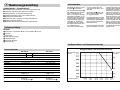
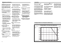
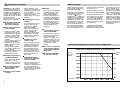
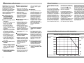
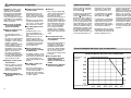
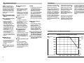
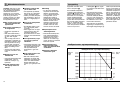
Das Gerät besitzt eine intelli-
gente Temperatur- und Luft-
mengenregulierung. Diese
gibt stets der Temperaturein-
stellung den Vorrang (siehe
Diagramm). Beispiel: Um die
maximale Temperatur von
600° C zu erreichen, bei
gleichzeitiger Einstellung der
Drehzahl auf max. Luftförde-
rung, regelt die Elektronik
automatisch die Luftmenge
soweit herunter, bis die
600° C erreicht werden.
Dementsprechend erhöht
sich die Luftmenge wieder,
sobald die Temperatur
gesenkt wird.
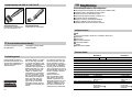
Intelligente Motor- und Temperatursteuerung
5
Intelligente Motor- und Temperatursteuerung
Dyn. Druck
(hPa)
Motordrehzalhl
(U/min.)
Austrittstemperatur
NFIN DK S E I NL FGB D
0
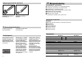
Bedienungsanleitung
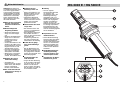
Gerätebeschreibung
Heißluftgebläse – Spezifikationen
yVollelektronische Temperatur- und Luftmengenregulierung
yLuftmenge und Temperatur stufenlos einstellbar
yIntelligente Motor- und Temperatursteuerung
yTemperaturanzeige mit Soll- und Ist-Wert-Anzeige
yHeizung leicht austauschbar
yBürstenloser Motor gewährt eine lange Lebensdauer
yStabiles einteiliges Gehäuse
yNetzkabel ohne Öffnen des Gehäuses auswechselbar
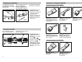
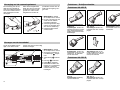
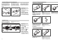
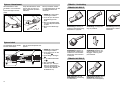
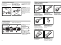
Bauteile
Ausblasrohr (HG 4000 E: 40 mm, HG 5000 E: 50 mm)
Heizung
Stoßschutz
LED-Segmentanzeige
Temperaturregler
EIN-/AUS-Schalter
Luftstromregler
Technische Daten
HG 4000 E HG 5000 E
Spannung: 100 V 110 V 230–240 V /50 Hz 230–240 V /50 Hz
Leistung: 1500 W 1650 W 1750 W 3400 W
Temperatur: 25–600°C, stufenlos 25–600°C, stufenlos
Anzeigeart: LED-Segmentanzeige LED-Segmentanzeige
Luftmengenregulierung: stufenlos stufenlos
Luftmenge: max. 600 l/min. max. 800 l/min.
Luftdruck: 3000 Pa 3000 Pa
Ausblasrohr: Ø 40 mm Ø 50 mm
Lebensdauer Motor: ca. 20 000 Std. ca. 20 000 Std.
Lebensdauer Heizung: ca. 500–800 Std. ca. 500–800 Std.
Netzkabel: H07 RN-F 2 x 1 H07 RN-F 2 x 1,5
Länge: 2,5 m Länge: 2,5 m
Gewicht (ohne Netzkabel): 1115 g 1190 g
Abmessungen: Länge: 370 mm Länge: 350 mm
Ø 122 mm Ø 122 mm
(am Stoßschutz ) (am Stoßschutz )
4
D

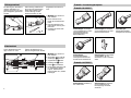
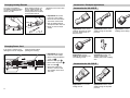
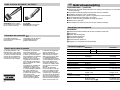
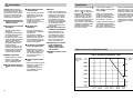
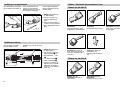
1. Wichtig! Das Gerät vom
Netz trennen.
2. Schrauben lösen und Ab-
deckkappe abziehen.
3. Zugentlastung lösen.
4. Netzklemmen lösen.
5. Kabel herausziehen.
6. Neues Kabel einlegen und
in umgekehrter Reihen-
folge (1. Netzklemmen
festschrauben etc.) wieder
befestigen.
Heizungswechsel
Die Heizung des HG 4000 E
und des HG 5000 E ist
gesteckt und kann mit weni-
gen Handgriffen gewechselt
werden.
Jede Heizung enthält einen
Chip mit ihren spezifischen
Daten. Beim Einbau einer
neuen Heizung werden
deren Parameter von der
1. Wichtig! Das Gerät vom
Netz trennen.
2. Die 4 Schrauben am
Ende des Ausblasrohres
lösen.
3. Heizung abziehen und
gegen neue Heizung aus-
tauschen.
4. Ausblasrohr wieder fest-
schrauben.
Regelelektronik übernom-
men.
Kabelwechsel
Ist das Netzkabel beschä-
digt, so kann es ohne
Öffnen des Gehäuses pro-
blemlos ausgetauscht werden.
b
c
a
d
a
b
c
d
6
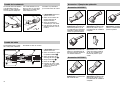
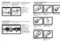
Zubehör / Anwendungsbeispiele
Zubehör HG 4000 E
Winkelflachdüse 40 x 2
Anwendungen: Schweißen
von Kunststoffolien im Über-
lappschweißverfahren.
Reparaturarbeiten bei
Bitumendächern.
Winkelflachdüse 20 x 2
Anwendungen: Schweißen
von Kunststoffolien im Über-
lappschweißverfahren.
Runddüse 5 mm
Anwendungen:
Kunststoffschweißen.
Punktgenaues Erwärmen.
Runddüse 10 mm
Anwendungen:
Kunststoffschweißen.
Punktgenaues Erwärmen.
Einsatz mit Schweißschuh.
Schweißschuh
Anwendungen: Aufschiebbar
auf Runddüse 10 mm.
Schweißen mit KU-Schweiß-
draht.
Zubehör HG 5000 E
Flachdüse 70 x 10
Anwendungen: Bündelung
des Luftstromes.
Winkelflachdüse 74 x 3
Anwendungen: Schweißen
von Kunststoffolien im
Überlappungs-Schweiß-
verfahren.
7
D

Funktionsgarantie
Dieses STEINEL-Produkt ist
mit größter Sorgfalt herge-
stellt, funktions- und sicher-
heitsgeprüft nach geltenden
Vorschriften und anschlie-
ßend einer Stichproben-
kontrolle unterzogen.
Die Funktionsgarantie be-
trägt 12 Monate und beginnt
mit dem Tag des Verkaufs
an den Verbraucher. Wir
beseitigen Mängel, die auf
Material- oder Fabrikations-
fehlern beruhen, die Garan-
tieleistung erfolgt durch
Instandsetzung oder Aus-
tausch mangelhafter Teile
nach unserer Wahl. Eine
Garantieleistung entfällt für
Schäden an Verschleißteilen,
z.B. Heizung, Netzkabel, für
Schäden und Mängel, die
durch unsachgemäße
Behandlung oder Wartung
auftreten sowie für Bruch bei
Sturz.
Weitergehende Folgeschä-
den an fremden Gegenstän-
den sind ausgeschlossen.
Die Garantie wird nur ge-
währt, wenn das unzerlegte
Gerät mit Kassenbon oder
Rechnung (Kaufdatum und
Händlerstempel), gut ver-
packt an die zutreffende
Servicestation eingesandt
oder in den ersten 6 Mona-
ten dem Händler übergeben
wird.
Reparaturservice:
Nach Ablauf der Garantiezeit
oder Mängel ohne Garantie-
anspruch repariert unser
Werksservice. Bitte das Pro-
dukt gut verpackt an die
nächste Servicestation
senden
Konformitätserklärung
Das Produkt erfüllt die
Niederspannungsrichtlinie 73/23/EWG und die EMV-
Richtlinie 89/336/EWG.
Hilfswerkzeuge HG 4000 E / HG 5000 E
Andrückrolle
Anwendungen: Andrücken
von Kantenumleimern, PVC-
Schweißfolie usw.
Schweißdrahtandrückrolle
Anwendungen: Andrücken
von Schweißdrähten.
8
0
Operating Instructions
Features
Hot air gun – specifications
yFully electronic temperature and air flow monitoring
yAir flow and temperature infinitely variable
yIntelligent motor and temperature control
yTemperature display showing target and actual temperature
yHeating element easily changed
yBrushless motor for long service life
ySturdy, one-piece housing
yPower cord can be changed without opening the housing
Components
Hot air outlet nozzle (HG 4000 E: 40 mm dia., HG 5000 E: 50 mm dia.)
Heating element
Rubber bumper
LED segment display
Temperature regulator
ON/OFF switch
Air-flow switch
Technical Specifications
HG 4000 E HG 5000 E
Voltage: 100 V 110 V 230–240 V /50 Hz 230–240 V /50 Hz
Output: 1500 W 1650 W 1750 W 3400 W
Temperature: 25–600°C, 25–600°C,
infinitely variable infinitely variable
Display type: LED segment display LED segment display
Air-flow control: Infinitely variable Infinitely variable
Max. air-flow rate: max. 600 l/min. max. 800 l/min.
Air pressure: 3000 Pa 3000 Pa
Air outlet nozzle: 40 mm dia. 50 mm dia.
Motor service life: approx. 20,000 hrs. approx. 20,000 hrs.
Heating element service life: approx. 500–800 hrs. approx. 500–800 hrs.
Power cord: H07 RN-F 2 x 1 H07 RN-F 2 x 1,5
Length: 2.5 m Length: 2.5 m
Weight (without power cord): 1115 g 1190 g
Dimensions: Length: 370 mm Length: 350 mm
122 mm dia. 122 mm dia.
(at rubber bumper ) (at rubber bumper )
9
GB

Safety Notification
Caution! When using electric
power tools, observe the fol-
lowing basic safety precau-
tions to avoid electric shock
as well as the risk of injury
and fire. Read and observe
this information before using
the tool.
yFire may be caused if the
tool is not used with care.
yTake ambient conditions
into account.
–Do not expose power tools
to rain.
–Do not use power tools
when they are damp or in
damp or wet surroundings.
–Exercise care when using
the tool in the proximity of
combustible materials. Do
not direct the tools at one
and the same place for a
prolonged period.
–Do not use in the pre-
sence of an explosive
atmosphere.
–Heat may be conducted to
combustible materials that
are out of sight.
yProtect yourself from
electric shock.
–Avoid touching grounded
equipment, such as piping,
radiators, cookers, refrige-
rators.
yDo not leave the appli-
ance unattended while in
operation.
yStore your tools in a safe
place.
–Place tool on its stand
after use and allow to cool
before storage.
–Tools that are not in use
should be stored in a dry,
locked room and be out of
the reach of children.
yDo not overload the tool.
–Your work results and
safety will be enhanced if
you operate the tool within
the specified output range.
–After using the tool for a
prolonged period at
600° C, you should reduce
the temperature before
switching it off. This will
prolong the service life of
the heating element.
yBeware of toxic gases
and ignition hazards.
–Toxic gases may occur
when working on plastics,
paints, varnishes or similar
materials. Beware of fire or
ignition hazards.
yDo not misuse the power
cord.
–Do not carry the tool by
the power cord and do not
use it to pull the plug from
the power socket outlet.
Protect the power cord
from heat, oil and sharp
edges.
yCaution
–For your own safety, use
only accessories and
attachments that are given
in the operating instruc-
tions or recommended or
specified by the tool
manufacturer. Using
attachments or accesso-
ries other than those
recommended in the
operating instructions or
catalogue may result in
personal injury.
yRepairs only by qualified
electricians.
–This power tool complies
with the relevant safety
regulations. Repairs
should only be performed
by a qualified electrician,
otherwise the user may
run the risk of accidents.
yFailure to observe the
operating instructions
may turn the tool into a
source of danger.
yKeep these safety notifi-
cations in a safe place.
Operation
Switch the tool on with
ON/OFF switch .
Use temperature switch to
preset the target temperatu-
re you require (25° C - 600°
C). The temperature setting
as well as the letter "A" to
show the setting mode will
appear on the LED segment
display. Once the tempera-
ture has been preset, the
tool will automatically dis-
play the actual temperature
after approx. 3 seconds.
Target and actual temperatu-
re is displayed in increments
of 10° C.
The air flow rate may be
infinitely varied using the
airflow regulator.
The control system complies
with the latest standards on
mains pollution
(EN 61000-3-3 Flicker
standard, EN 61000-3-2
Harmonics standard).
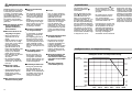
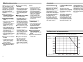
The tool features an intelli-
gent temperature and
airflow control system that
always gives priority to tem-
perature setting (see graph).
Example: To attain the maxi-
mum temperature of 600° C
with speed set to max. air
flow rate, the electronics will
automatically reduce air flow
until 600° C is reached. The
airflow rate will then in-
crease again as soon as the
temperature is reduced.
Intelligent Motor and Temperature Monitoring
Intelligent Motor and Temperature Monitoring
Motor speed
(rpm)
Dyn. pressure
(hPa)
Outlet temperature
10 11
GB

1. Important! Disconnect
tool from power supply.
2. Undo screws and detach
cover cap .
3. Release cable grip .
4. Undo mains terminals .
5. Pull out cable .
6. Insert new cable and
secure in reverse order
(first tighten mains termi-
nals, etc.).
Changing Heating Element
The plug-in HG 4000 E/
HG 5000 E heating element
can be changed/replaced
within seconds.
Each heating element con-
tains a chip that holds its
specific data. When a new
heating element is installed,
its parameters will be
1. Important! Disconnect
tool from power supply.
2. Undo the 4 screws at the
end of the outlet nozzle.
3. Pull off heating element
and replace with new one.
4. Firmly re-secure output
nozzle.
adopted by the control elec-
tronics.
Changing Power Cord
Accessories / Example Applications
Accessories for HG 4000 E
40 x 2 offset flat nozzle
Applications: Plastic sheet
welding using the lap weld
process. Repair work on
bitumen roofs.
20 x 2 offset flat nozzle
Applications: Plastic sheet
welding using the lap weld
process.
5 mm round nozzle
Applications: Plastics
welding. Spot heating.
10 mm round nozzle
Applications: Plastics
welding. Spot heating. Use
with welding nozzle.
Welding nozzle
Applications: Pushes onto
10 mm round nozzle.
Welding with plastic welding
wire.
Accessories for HG 5000 E
70 x 10 flat nozzle
Applications: For concen-
trating air flow.
74 x 3 offset flat nozzle
Applications: Plastic sheet
welding using the lap weld
process.
If the power cord becomes
damaged it can be changed/
replaced easily without
opening the housing.
b
c
a
b
c
d
a
d
12 13
GB

Functional Guarantee
This STEINEL product has
been manufactured with
great care, performance
and safety tested accor-
ding to current regulations,
and then subjected to a
batch test.
STEINEL guarantees that it
is in perfect condition and
functions correctly. The
correct working order of this
product is guaranteed for a
period of 12 months com-
mencing on the date of sale
to the user. All defects due
to faulty material or manu-
facturing will be corrected.
This warranty does not
cover damage to wear parts,
e.g. heating element, power
cord, or damage and faults
caused by incorrect operati-
on and maintenance.
Breakage due to a fall is
also not covered.
Further consequential
damage to other items is
excluded.
Claims under the guarantee
will only be granted if the
product, not disassembled,
with sales slip or invoice
(date of purchase and
dealer’s stamp) is sent, well
packed, to the appropriate
Service Centre, or handed
in to the dealer within the
first 6 months.
Repair-Service
Our customer service de-
partment will repair faults
not covered by the guaran-
tee, or after the guarantee
has expired. Please send
the product, well packed, to
the nearest Service Centre.
Declaration of conformity
This product is in confor-
mity with standards of low
voltage in accordance with
the regulations 73/23/EEC,
89/336/EEC.
Auxiliary tools for HG 4000 E / HG 5000 E
Feed roller
Applications: For pressing
down edgebands, PVC filler
strip.
Welding wire feed roller
Applications: For pressing
down welding wire.
14
2
0
Mode d'emploi
Description de l'appareil
Générateur d’air chaud – Spécifications
yRéglage électronique de la température et du débit d'air
yRéglage en continu du débit d'air et de la température
yCommande intelligente du moteur et de la température
yAffichage de la température avec valeur souhaitée et valeur effective
yRésistance facile à remplacer
yLe moteur sans balai garantit une durée de vie élevée
yBoîtier robuste en un élément
yChangement du câble secteur possible sans ouverture du boîtier de l'appareil
Composants
Tuyère de propulsion d'air (HG 4000 E: 40 mm, HG 5000 E: 50 mm)
Chauffage
Protection antichoc
Afficheur à segments LED
Régulateur de température
Interrupteur MARCHE/ARRÊT
Réglage du débit d'air
Caractéristiques techniques
HG 4000 E HG 5000 E
Tension: 100 V 110 V 230–240 V /50 Hz 230–240 V /50 Hz
Puissance: 1500 W 1650 W 1750 W 3400 W
Température: 25–600°C, en continu 25–600°C, en continu
Type d'affichage: affichage LED affichage LED
à segments à segments
Réglage du débit d'air: en continu en continu
Débit d'air: 600 l/min maxi 800 l/min maxi
Pression d'air: 3000 Pa 3000 Pa
Tube de propulsion d'air: Ø 40 mm Ø 50 mm
Durée de vie du moteur: env. 20 000 h env. 20 000 h
Durée de vie de
la résistance: env. 500-800 h. env. 500-800 h
Câble secteur : H07 RN-F 2 x 1 H07 RN-F 2 x 1,5
Longueur: 2,5 m Longueur: 2,5 m
Poids (sans câble secteur): 1115 g 1190 g
Dimensions: Longueur: 370 mm Longueur: 350 mm
Ø 122 mm Ø 122 mm
(au niveau de (au niveau de la
la protection antichoc ) protection antichoc )
15
F
F

Consignes de sécurité
Attention! Lors de l'utilisati-
on d'outillage électrique, il
est absolument impératif de
respecter les consignes de
sécurité suivantes afin de se
protéger des accidents élec-
triques, des risques de bles-
sure et d'incendie.
Veuillez lire ces consignes
avant d'utiliser l'appareil.
yUn incendie peut survenir
si l'appareil n'est pas
manié avec précaution.
yTenez compte des condi-
tions ambiantes.
–N'exposez jamais l'outilla-
ge électrique à la pluie.
–N'utilisez jamais l'appareil
si vous ou l'appareil êtes
mouillés ou vous trouvez
dans un environnement
humide.
–Ne pas utiliser l'appareil à
proximité de matières
inflammables et ne pas le
diriger longtemps vers le
même endroit.
–Ne pas utiliser l'appareil
en présence d'une atmos-
phère explosive.
–La chaleur peut être trans-
mise à des matériaux
inflammables cachés.
yProtégez-vous contre les
accidents électriques.
–Évitez de toucher des élé-
ments mis à la terre
comme tuyaux, radiateurs,
cuisinières, réfrigérateurs.
yNe pas laisser l'appareil
sans surveillance tant
qu'il fonctionne.
yConservez votre outillage
en sûreté.
–Après utilisation, poser
l'appareil sur son support
et le laisser refroidir avant
de le remballer.
–Il faut conserver les outils
hors de portée des
enfants dans un local sec
et fermé.
yNe surchargez pas votre
outillage.
–Vous travaillerez mieux et
de façon plus sûre en
respectant la plage de
puissance indiquée.
–Après une utilisation pro-
longée de l'appareil à
600° C, réduisez la
température avant d'arrê-
ter l'appareil. Vous aug-
mentez ainsi la durée de
vie du chauffage.
yAttention aux gaz et
vapeurs nocifs.
–Si vous travaillez sur des
matières plastiques, des
peintures, des vernis ou
des produits similaires,
des émanations de gaz
toxiques peuvent se pro-
duire sous l'action de la
chaleur. Attention aux ris-
ques d'incendie et d'in-
flammation.
yUtilisation du câble de
l'appareil en conformité
avec ses fonctions.
–Ne vous servez jamais du
câble pour transporter
l'appareil ou débrancher la
fiche de la prise électri-
que. Protégez le câble de
la chaleur, de l'huile et des
arêtes coupantes.
yAttention
–Pour votre propre sécurité,
n'utilisez que des acces-
soires et appareils com-
plémentaires indiqués
dans le mode d'emploi ou
conseillés ou indiqués par
le fabricant de l'outillage.
Vous pouvez vous blesser
en utilisant des outils ou
des accessoires autres
que ceux conseillés dans
le mode d'emploi ou le
catalogue.
yLes réparations sont une
affaire de spécialiste.
–Cet outillage électrique est
conforme à la réglementa-
tion de sécurité en
vigueur. Pour éviter les ris-
ques d'accident pour l'uti-
lisateur, les réparations ne
doivent être confiées qu'à
un électricien profes-
sionnel.
yEn cas de non-respect du
mode d'emploi, l'utilisati-
on de l'appareil peut être
dangereuse.
yConservez les consignes
de sécurité en lieu sûr.
Mise en service
Mettre l'appareil sous tensi-
on à l'aide de l'interrupteur
MARCHE/ARRÊT .
Sélectionner la température
souhaitée (25° C-600° C) à
l'aide du régulateur de
température . L'afficheur à
segments de LED indique la
température et la lettre «A»
signalant le mode de régla-
ge. Au bout de 3 secondes
environ après la présélec-
tion de la température, l'ap-
pareil affiche automatique-
ment la température effec-
tive. Les températures sou-
haitée et effective s'affichent
par pas de 10° C.
On règle le débit d'air à l'ai-
de du bouton de réglage .
La régulation est conforme
aux normes les plus récen-
tes relatives aux perturbati-
ons sur le réseau (norme
sur le flicker EN 61000-3-3,
norme sur les harmoniques
EN 61000-3-2).
L'appareil est muni d'une
régulation intelligente de la
température et du débit d'air
qui donne toujours la prio-
rité au réglage de la
température (cf. diagramme).
Exemple : pour obtenir la
température maximum de
600° C, la vitesse étant
réglée sur le débit d'air
maximum, le système élec-
tronique réduit le débit d'air
jusqu'à ce que la températu-
re de 600° C soit atteinte. À
l'inverse, le débit d'air aug-
mente dès que l'on réduit la
température.
Commande intelligente du moteur et de la température
Commande intelligente du moteur et de la température
Vitesse
du moteur
(tr/min)
Pression dyn.
(hPa)
Température de sortie
16 17
F

1. Important! Débrancher
l'appareil du secteur.
2. Desserrer les vis et retirer
le cache .
3. Desserrer l'étrier .
4. Desserrer les bornes .
5. Retirer le câble .
6. Mettre en place un nou-
veau câble et le fixer en
procédant dans l'ordre
inverse (1. Visser les bor-
nes, etc.).
Changement du chauffage
Le chauffage du HG 4000 E
et du HG 5000 E est simple-
ment enfiché et il se change
très facilement.
Chaque chauffage est muni
d'un ci contenant ses
données caractéristiques.
Lors du montage d'un nou-
veau chauffage, le système
1. Important! Débrancher
l'appareil du secteur.
2. Desserrer les quatre vis à
l'extrémité du tube de
propulsion d'air.
3. Retirer le chauffage et le
remplacer par un neuf.
4. Revisser le tube de pro-
pulsion d'air.
de régulation électronique
en reprend les paramètres.
Changement de câble
Accessoires / exemples d'utilisation
Accessoires pour le HG 4000 E
Buse plate coudée 40 x 2
Applications: soudage de
films plastiques par recou-
vrement, réparation de toitu-
res bitumées.
Buse plate coudée 20 x 2
Applications: soudage de
films plastiques par
recouvrement.
Buse ronde 5 mm
Applications: soudage de
matières plastiques, chauffa-
ge ponctuel.
Buse ronde 10 mm
Applications: soudage de
matières plastiques, chauffa-
ge ponctuel. Utilisation avec
buse à souder.
Buse à souder
Applications: S'emboîte sur
la buse ronde de 10 mm.
Soudage avec baguette à
souder en matière plastique.
Accessoires pour le HG 5000 E
Buse plate 70 x 10
Applications: concentration
du jet d'air.
Buse plate coudée 74 x 3
Applications: soudage de
films plastiques par
recouvrement.
En cas de détérioration du
câble, il est très facile de le
changer sans avoir à ouvrir le
boîtier de l'appareil.
b
c
a
b
c
d
a
d
18 19
F

Service après-vente et garantie
Ce produit STEINEL a été
fabriqué avec le plus grand
soin. Son fonctionnement et
sa sécurité ont été contrôlés
suivant des procédures fia-
bles et il a été soumis à un
contrôle final par sondage.
La durée de la garantie de
fonctionnement est de
12 mois et débute au jour de
la vente au consommateur.
Nous remédions aux défauts
provenant d'un vice de
matière ou de construction.
La garantie sera assurée à
notre discrétion par répara-
tion ou échange de la pièce
défectueuse.
La garantie ne s’applique ni
aux pièces d’usure, p.ex.
chauffage ou câble secteur,
ni aux dommages et défauts
dus à une utilisation ou
maintenance incorrectes,
ni aux bris de pièces consé-
cutifs à une chute.
Les dommages consécutifs
causés à d'autres objets
sont exclus de la garantie.
La garantie ne s'applique
que si l'appareil non
démonté est retourné à la
station de service après-
vente la plus proche, dans
un emballage adéquat,
accompagné d'une facture
ou d'un ticket de caisse por-
tant la date d'achat et le
cachet du vendeur ou s'il
est remis au vendeur dans
les 6 premiers mois de la
garantie.
Service de réparation:
Le service après-vente de
notre usine effectue égale-
ment les réparations non
couvertes par la garantie ou
survenant après l'expiration
de celle-ci. Envoyez le pro-
duit correctement emballé à
la station de service après
vente la plus proche s.v.p.
Déclaration de conformité
Ce produit répond aux
prescriptions de la directive
basse tension
73/23/CEE et de la directive
Compatibilité Électroma-
gnétique 89/336/CEE.
Outils auxiliaires HG 4000 E / HG 5000 E
Rouleau presseur
Applications: pour écraser
les chants thermocollants, le
film à souder en PVC etc.
Rouleau presseur à baguet-
te à souder
Applications: pour écraser
les baguettes à souder.
20
0
Gebruiksaanwijzing
Beschrijving van het apparaat
Heteluchtbrander – specificatie
yElektronisch geregelde heteluchtbrander met regeling van temperatuur en hoeveelheid
luchtverplaatsing
yHoeveelheid luchtverplaatsing en temperatuur traploos instelbaar
yIntelligente sturing van motor en temperatuur
yTemperatuuraanwijzing met opgave van gewenste en actuele waarde
yVerwarmingselement eenvoudig te vervangen
yMotor zonder borstels garandeert een lange levensduur
yStabiel huis uit één stuk
yStroomkabel kan zonder openen van het huis worden vervangen
Onderdelen
Uitblaasmondstuk (HG 4000 E: 40 mm, HG 5000 E: 50 mm)
Verwarming
Rubber beschermingsring
LED-segment-aanwijzing
Temperatuurregelknop
Keuzeschakelaar (AAN/UIT)
Regeling voor hoeveelheid luchtverplaatsing
Technische gegevens
HG 4000 E HG 5000 E
Spanning: 100 V 110 V 230–240 V /50 Hz 230–240 V /50 Hz
Vermogen: 1500 W 1650 W 1750 W 3400 W
Temperatuur: 25–600° C, traploos 25–600° C, traploos
Soort aanwijzing: LED-segment- LED-segment-
aanwijzing aanwijzing
Regeling luchtverplaatsing: traploos traploos
Luchthoeveelheid: max. 600 l/min. max. 800 l/min.
Luchtdruk: 3000 Pa 3000 Pa
Uitblaasmondstuk: Ø 40 mm Ø 50 mm
Levensduur motor: ca. 20 000 uren ca. 20 000 uren
Levensduur
verwarmingselement: ca. 500-800 uren ca. 500-800 uren
Stroomkabel: H07 RN-F 2 x 1 H07 RN-F 2 x 1,5
Lengte: 2,5 m Lengte: 2,5 m
Gewicht
(zonder stroomkabel): 1115 g 1190 g
Afmetingen: Lengte: 370 mm Lengte: 350 mm
Ø 122 mm (aan Ø 122 mm (aan
beschermingsring ) beschermingsring )
21
NL

Veiligheidsvoorschriften
Let op! Bij gebruik van elek-
trische apparaten moeten ter
voorkoming van elektrische
schokken, lichamelijk letsel
en brandgevaar de volgende
veiligheidsmaatregelen
genomen worden. Lees en
let op deze voorschriften,
voordat u het apparaat gaat
gebruiken.
yAls het apparaat niet met
grote zorgvuldigheid
gebruikt wordt, kan er
brand ontstaan.
yHoud de invloed van de
omgeving in de gaten.
–Werk met elektrische
apparaten niet in de
regen.
–Gebruik elektrische appa-
raten niet als ze vochtig
zijn en niet in een natte of
vochtige omgeving.
–Het apparaat mag niet
gebruikt worden in de
buurt van brandbare mate-
rialen. Niet gedurende
lange tijd op dezelfde
plaats gericht houden.
–Niet gebruiken in de buurt
van een explosieve
atmosfeer.
–De warmte kan geleid
worden naar brandbare
materialen, die niet zicht-
baar zijn.
yBescherm u tegen
elektrische schokken.
–Vermijd aanraking met
geaarde delen, bijvoor-
beeld buizen, verwar-
mingselementen, ovens,
koelkasten.
yHet apparaat nooit zonder
toezicht in werking laten.
yBerg uw gereedschap
veilig op.
–Het apparaat na gebruik
op de beschermingsring
zetten en laten afkoelen,
voordat het opgeborgen
wordt.
–Ongebruikt gereedschap
moet droog, in een afge-
sloten ruimte en voor kin-
deren niet bereikbaar
opgeborgen worden.
yVoorkom overbelasting
van uw gereedschap.
–U werkt beter en veiliger
binnen het aangegeven
vermogen.
–Na langdurig gebruik op
600°C moet voor het uit-
schakelen van het appa-
raat de temperatuur eerst
lager ingesteld worden.
Hierdoor wordt de levens-
duur van het apparaat ver-
lengd.
yLet op giftige gassen en
verbrandingsgevaar.
–Bij het verwerken van
kunststoffen, lakken en
soortgelijke materialen
kunnen giftige gassen vrij-
komen. Let op brand- en
ontbrandingsgevaar.
yBeschadig de kabel niet.
–Draag het gereedschap
niet aan de kabel en
gebruik deze niet om de
stekker uit de stekkerdoos
te trekken. Bescherm de
kabel tegen hitte, olie en
scherpe voorwerpen.
yLet op!
–Voor uw eigen veiligheid
alleen toebehoren en aan-
vullend gereedschap
gebruiken, dat in de
gebruiksaanwijzing staat
of door de fabrikant wordt
aanbevolen of aangege-
ven. Het gebruik van
andere dan in de gebruik-
saanwijzing of in de cata-
logus aanbevolen gereed-
schap of toebehoren kun-
nen leiden tot persoonlijk
letsel.
yReparatie uitsluitend door
de elektro-vakman.
–Dit elektrische apparaat
voldoet aan de voorge-
schreven veiligheidsvoor-
schriften. Reparaties
mogen uitsluitend worden
verricht door een elektro-
vakman, anders kunnen
ongelukken ontstaan voor
de gebruiker.
yBij het niet-opvolgen van
de gebruiksaanwijzing
kan werken met het appa-
raat leiden tot gevaarlijke
situaties.
yBerg deze veiligheids-
voorschriften goed op.
Ingebruikname
Het apparaat met de
AAN/UIT-schakelaar
inschakelen.
Met de temperatuurregel-
knop de gewenste tem-
peratuur kiezen (25° C -
600° C). De temperatuur-
waarde en de letter „A“ voor
de instelmodus worden op
de LED-segmentaanwijzing
getoond. Nadat de tempera-
tuur gekozen is, schakelt het
apparaat na ca. 3 seconden
automatisch op de actuele
temperatuurwaarde om. De
aanwijzing van de gewenste
en de actuele waarden volgt
in stappen van 10° C.
De luchtverplaatsing kan
met de regelknop voor de
luchtstroom traploos worden
geregeld.
De regeling komt overeen
met de nieuwste normen
voor netvervuilingen
(volgens normen EN 61000-
3-3 en EN 61000-3-2).
Het apparaat is voorzien van
een intelligente regeling voor
de temperatuur en de hoe-
veelheid luchtverplaatsing.
Deze regeling geeft aan de
temperatuurinstelling altijd
voorrang (zie diagram)
Voorbeeld: Om de maximale
temperatuur van 600° C te
bereiken, bij een gelijktijdige
instelling van het toerental
op de maximale luchtver-
plaatsing, wordt elektronisch
de luchthoeveelheid ver-
laagd tot de temperatuur
van 600° C is bereikt. Zo
wordt ook de luchthoeveel-
heid weer verhoogd, als de
temperatuur wordt verlaagd.
Intelligente motor- en temperatuursturing
Intelligente motor- en temperatuursturing
Toerental
motor (o/min.)
Dyn. druk
(hPa)
Uitblaastemperatuur
22 23
NL

1. Belangrijk! De stekker
uit het stopcontact nemen.
2. Schroeven losdraaien en
het afdekkapje wegne-
men.
3. Trekontlasting losdraai-
en.
4. Klemmen losdraaien.
5. Kabel er uittrekken.
6. Nieuwe stroomkabel erin
leggen en in omgekeerde
volgorde (1. klemmen
vastschroeven, etc.) weer
bevestigen.
Vervanging van het verwarmingselement
De verwarming van de HG
4000 E en de HG 5000 E
heeft een stekkeraansluiting
en kan met enkele eenvou-
dige handgrepen worden
vervangen.
Ieder verwarmingselement
bevat een chip met specifie-
ke gegevens. Bij de monta-
ge van een nieuw verwar-
mingselement worden de
1. Belangrijk! De stekker
uit het stopcontact nemen.
2. De vier schroeven aan het
einde van het uitblaas-
mondstuk losdraaien.
3. Verwarmingselement weg-
nemen en vervangen door
een nieuwe verwarming.
4. Uitblaasmondstuk weer
vastschroeven.
parameters hiervan door de
elektronische regeling over-
genomen.
Vervangen van de stroomkabel
Toebehoren / Praktijkvoorbeelden
Toebehoren HG 4000 E
Haaks breedtstraalmond-
stuk 40 x 2
Toepassingen: lassen van
kunststof folie door overlap-
ping. Reparatiewerkzaam-
heden bij bitumineuze dak-
bedekkingen.
Haaks breedtstraalmond-
stuk 20 x 2
Toepassingen: lassen van
kunststof folie door overlap-
pingen.
Rond mondstuk 5 mm
Toepassingen: lassen van
kunststoffen. Punt voor punt
verwarmen.
Rond mondstuk 10 mm
Toepassingen: lassen van
kunststoffen. Punt voor punt
verwarmen. Te gebruiken
met de lasschoen.
Lasschoen
Toepassingen: kan op het
ronde mondstuk van 10 mm
worden geschoven. Lassen
met koper-lasdraad.
Toebehoren HG 5000 E
Breedtstraalmondstuk
70 x 10
Toepassingen: bundeling
van de luchtstroom.
Haaks breedtstraalmond-
stuk 74 x 3
Toepassingen: lassen van
kunststof folie door overlap-
pingen.
Als de stroomkabel bescha-
digd is, kan deze zonder
openen van het huis eenvoudig
worden vervangen.
b
c
a
b
c
d
a
24 25
NL
d

Functie-garantie
Dit STEINEL-product is met
grote zorgvuldigheid gefabri-
ceerd, getest op goede wer-
king en veiligheid volgens
de geldende voorschriften
en aansluitend steekproef-
gewijs gecontroleerd.
De functie-garantie bedraagt
12 maanden en gaat in op
de datum van de aanschaf
door de klant. Alle klachten,
die berusten op materiaal-
of fabricagefouten, worden
door ons opgelost. De
garantie bestaat uit reparatie
of vernieuwen van de defec-
te onderdelen, door ons te
beoordelen.
Garantie vervalt bij schade
aan onderdelen, die aan
slijtage onderhevig zijn,
bijvoorbeeld verwarming,
stroomkabels, bij schade of
gebreken, die door ondes-
kundig gebruik of onder-
houd ontstaan, alsmede bij
breuk door vallen. Schade
aan aangesloten randappa-
ratuur is uitgesloten van
garantie.
De garantie wordt alleen
verleend, als het, niet gede-
monteerde, apparaat met
kassabon of rekening (met
aankoopdatum en winke-
liersstempel), goed verpakt
naar ons service-adres
wordt opgestuurd of binnen
de eerste 6 maanden naar
de winkelier teruggebracht
wordt.
Reparatie-service:
Na afloop van de garantie-
termijn of bij schade die niet
onder garantie valt, kan ook
door ons gerepareerd wor-
den. Gelieve het product
goed verpakt naar het
dichtstbijzijnde service-
adres op te sturen.
Verklaring -richtlijnen
Het product voldoet aan de
laagspanningsrichtlijn 73/23/EWG en de EVM-
richtlijn 89/336 EWG.
Hulpstukken HG 4000 E / HG 5000 E
Aandrukrol
Toepassingen: aandrukken
van aangelijmde kanten,
PVC-lasfolie etc.
Aandrukrol voor lasdraad
Toepassingen: aandrukken
van lasdraad.
26
0
Istruzioni per l'uso
Descrizione di apparecchio
Soffiante ad aria calda – Specificazioni
yRegolazioni completamente elettroniche di temperatura e volume d'aria
yImpostazioni in continuo per volume d'aria e temperatura
yComando intelligente di motore e temperatura
yPer la temperatura vengono indicati sia i valori nominali che quelli reali
yFacilità di cambio dell'elemento di riscaldamento
yMotore senza spazzole, pertanto di più lunga durata
yCarcassa stabile monoblocco
yIl cavo di allacciamento a rete si sostituisce senza necessità di aprire la carcassa
Componenti
Condotto di soffiaggio (HG 4000 E: 40 mm, HG 5000 E: 50 mm)
Riscaldamento
Protezione antiurto
Display LED a segmenti
Termoregolatore
Interruttore ON/OFF
Regolatore del flusso d'aria
Dati tecnici
HG 4000 E HG 5000 E
Tensione: 100 V 110 V 230–240 V /50 Hz 230–240 V/ 50 Hz
Potenza: 1500 W 1650 W 1750 W 3400 W
Temperatura: 25–600°C, in continuo 25–600°C, in continuo
Tipo di display: LED a segmenti LED a segmenti
Regolazione flusso d'aria: in continuo in continuo
Flusso d'aria: max. 600 l/min. max. 800 l/min.
Pressione dell'aria: 3000 Pa 3000 Pa
Condotto di soffiaggio: Ø 40 mm Ø 50 mm
Durata di motore: circa 20 000 ore circa 20 000 ore
Durata di riscaldamento: circa 500-800 ore circa 500-800 ore
Cavo allacciamento a rete: H07 RN-F 2 x 1 H07 RN-F 2 x 1,5
Lunghezza: 2,5 m Lunghezza: 2,5 m
Peso
(senza cavo allacc. rete): 1115 g 1190 g
Dimensioni: Lunghezza: 370 mm Lunghezza: 350 mm
Ø 122 mm Ø 122 mm
(su protezione antiurto ) (su protezione antiurto )
27
I
I

Avvertenze sulla sicurezza
Attenzione! Quando si usano
utensili elettrici è necessario
osservare le seguenti norme
fondamentali per potersi
proteggere da scosse elettri-
che, pericoli di lesioni e di
incendio. Leggete attenta-
mente le presenti avvertenze
sulla sicurezza prima di
usare l'apparecchio.
ySe l'apparecchio non
viene maneggiato con
precauzione sussiste il
pericolo di incendio.
yTenete conto degli influssi
atmosferici.
–Gli apparecchi elettrici non
devono venir lasciati
esposti alla pioggia.
–Non usare mai l'appa-
recchio in stato umido
oppure in ambiente umido
o bagnato.
–Attenzione a come usate
l'apparecchio in prossimità
di materiali combustibili.
Non dirigere mai l'appa-
recchio a lungo verso uno
stesso punto.
–Non azionate mai l'appa-
recchio in presenza di
miscugli gassosi esplosivi.
–Il calore può venire tras-
messo a materiali combu-
stibili coperti e dunque
non visibili.
yProteggetevi dalle scosse
elettriche.
–Evitate il contatto corporeo
con parti collegate a terra,
come p. es. tubi, elementi
di riscaldamento, cucine,
frigoriferi.
yTenete sempre d'occhio
l'apparecchio fintanto che
si trova in funzione
yMettete l'apparecchio da
parte in un posto sicuro.
–Dopo l'uso riponete l'ap-
parecchio sul suo piano di
appoggio ed attendete che
si raffreddi prima di richiu-
derlo in scatola.
–Mettete da parte l'appa-
recchio in un ambiente
secco, che si chiude a
chiave, di modo che i
bambini non possano
prenderlo in mano.
yEvitate sovraccarichi per i
vostri utensili.
–Si lavora meglio e con
maggiore sicurezza rima-
nendo nell'ambito delle
prestazioni indicate.
–Quando lavorate a lungo
con apparecchio a 600° C,
prima di disinserirlo è
opportuno regolare la tem-
peratura su un valore piú
basso. In tal modo prolun-
gate la durata di vita dell'-
apparecchio.
yFate attenzione ai gas
velenosi ed al pericolo di
provocare fiamme.
–Quando si lavorano mate-
rie plastiche, vernici e altri
materiali di questo genere
possono liberarsi dei gas
velenosi. Fate attenzione
ad evitare il pericolo di
provocare fiamme e
incendi.
yNon usare mai il cavo in
modo improprio.
–Non trasportate mai l'ap-
parecchio tenendolo
appeso al cavo e non tira-
te il cavo per staccare la
spina dalla presa di cor-
rente. Proteggete il cavo
da calore, olio e spigoli
taglienti.
yAttenzione
–Onde garantire la vostra
sicurezza personale impie-
gate esclusivamente
accessori ed apparecchi
di complemento indicati
nelle istruzioni per l'uso
oppure raccomandati o
indicati dal fabbricante
dell'apparecchio. Se si
impiegano degli accessori
o apparecchi di comple-
mento diversi da quelli
indicati nelle istruzioni per
l'uso o nel catalogo,
sussiste il pericolo di
lesioni.
yPer riparazioni rivolgetevi
sempre ad un elettrotec-
nico.
–Il presente apparecchio è
stato fabbricato in corris-
pondenza delle vigenti dis-
posizioni di sicurezza. Per
eventuali riparazioni biso-
gna rivolgersi sempre ad
un elettrotecnico, altrimenti
sussiste il rischio di inci-
denti nell'uso dell'appa-
recchio.
ySe non vengono rispetta-
te le istruzioni per l'uso,
l'apparecchio può diven-
tare fonte di pericolo.
yConservate in un posto
sicuro le avvertenze sulla
sicurezza.
Messa in funzione
Inserite l'apparecchio azio-
nando l'interruttore ON/OFF
.
Con il termoregolatore
preimpostate la temperatura
nominale desiderata (25° C-
600° C). Sul display LED a
segmenti vengono visuali-
zzati il valore di temperatura
e la lettera «A», che indica la
modalità di impostazione.
Una volta avvenuta la prese-
lezione di temperatura, l'ap-
parecchio si commuta dopo
circa 3 secondi automatica-
mente sulla visualizzazione
del valore reale di tempera-
tura. L'indicazione dei valori
nominali e reali di tempera-
tura avviene a passi di 10° C.
Il flusso d'aria si può
regolare in continuo con
l'apposito regolatore.
La regolazione avviene in
osservanza delle più recenti
norme relative alla reazione
sulla rete elettrica (EN
61000-3-3 Norma sulla
distorsione di secondo ordi-
ne, EN 61000-3-2 Norma
sulle armoniche).
L'apparecchio è dotato di un
sistema intelligente per la
regolazione della temperatu-
ra e del flusso d'aria. Questo
sistema dà sempre la prece-
denza all'impostazione di
temperatura (vedasi dia-
gramma). Per esempio: al
fine di raggiungere la tem-
peratura massima di 600° C,
con contemporanea regola-
zione del numero di giri in
corrispondenza del flusso
massimo d'aria, il sistema
elettronico regola automati-
camente il flusso d'aria su
valori minori, fino a quando
viene raggiunta la tempera-
tura di 600° C. Analogamente
il flusso d'aria aumenta poi,
non appena la temperatura
viene abbassata.
Comando intelligente del motore e della temperatura
Comando intelligente del motore e della temperatura
No. giri motore
(giri/min)
Pressione
dinamica
(hPa)
Temperatura in uscita
28 29
I

1. Importante! Staccate
l'apparecchio dall'alimen-
tazione di rete.
2. Allentate le viti e staccate
il coperchio .
3. Allentate lo scarico di tra-
zione .
4. Allentate i morsetti di col-
legamento a rete .
5. Estraete il cavo .
6. Inserite il nuovo cavo e
rifate le operazioni qui
descritte in senso inverso
(1. Avvitate i morsetti di
collegamento a rete, ecc.).
Cambio dell'elemento di riscaldamento
Nel caso degli apparecchi
HG 4000 E e HG 5000 E si
tratta di elementi di riscalda-
mento scambiabili, che si
possono inserire con molta
facilità.
Ogni elemento di riscalda-
mento è dotato di un chip
con riportati i suoi dati spe-
cifici. Quando si installa un
elemento nuovo di riscalda-
1. Importante! Staccate
l'apparecchio dall'alimen-
tazione di rete.
2. Allentate le quattro viti
all'estremità del condotto
di soffiaggio.
3. Estraete il vecchio ele-
mento di riscaldamento
ed inserite quello nuovo.
4. Fissate nuovamente con
viti il condotto di soffiaggio.
mento, il sistema elettronico
di regolazione si regola in
base ai parametri del nuovo
elemento di riscaldamento.
Cambio di cavo
Accessori / Esempi di applicazione
Accessori per HG 4000 E
Ugello appiattito e angolato
40 x 2
Impieghi: Saldatura di fogli
di plastica con processo di
saldatura a sovrapposizione.
Riparazioni di tetti coperti
con bitume.
Ugello appiattito e angolato
20 x 2
Impieghi: Saldatura di fogli
di plastica con processo di
saldatura a sovrapposizione.
Ugello rotondo 5 mm
Impieghi: Saldatura di mate-
rie plastiche. Riscaldamento
preciso di punti particolari.
Ugello rotondo 10 mm
Impieghi: Saldatura di mate-
rie plastiche. Riscaldamento
preciso di punti particolari.
Applicazione con zoccolo
per saldatura.
Zoccolo per saldatura
Impieghi: Applicabile su
ugello rotondo 10 mm.
Saldatura con filo di apporto
in plastica.
Accessori per HG 5000 E
Ugello appiattito 70 x 10
Impieghi: Concentrazione
del flusso d'aria.
Ugello appiattito e angolato
74 x 3
Impieghi: Saldatura di fogli
di plastica con processo di
saldatura a sovrapposizione.
Quando il cavo di allaccia-
mento a rete viene danneg-
giato, si può cambiare con
facilità senza dover aprire la
carcassa.
b
c
a
b
c
d
a
30 31
I
d

Garanzia di funzionamento
Questo prodotto STEINEL
viene prodotto con la massi-
ma cura, con controlli di
funzionamento e del grado
di sicurezza in corrispon-
denza alle norme vigenti in
materia; vengono poi effet-
tuati collaudi con prove di
campionamento.
La garanzia di funzionamen-
to si estende a 12 mesi ed
inizia il giorno d’acquisto
dall’utilizzatore. Ripariamo
guasti dovuti a difetti di
materiale o produzione. Le
prestazioni di garanzia com-
prendono - a nostra scelta -
la riparazione o la sostituzio-
ne degli elementi difettosi.
Non sussiste nessun diritto
di garanzia in caso di difetti
sui pezzi soggetti ad usura,
p. es. nel caso del riscalda-
mento, cavo di allacciamen-
to a rete, ed in caso di gua-
sti o difetti insorti in seguito
a trattamento o manutenzio-
ne impropri, come anche nel
in seguito a cadute caso di
rotture. Sono esclusi dal
diritto di garanzia danni pro-
vocati ad oggetti estranei.
Si può far valere il diritto di
garanzia soltanto inviando
l'apparecchio propriamente
imballato ed accompagnato
dallo scontrino di cassa o
dalla fattura (con data di
acquisto e timbro del nego-
ziante) al competente punto
di assistenza tecnica, oppu-
re consegnando l'appa-
recchio al negoziante entro i
primi 6 mesi di garanzia.
Centro assistenza tecnica:
Con periodo di garanzia
scaduto e nel caso di difetti
che non danno diritto a pre-
stazioni di garanzia, il nostro
centro di assistenza esegue
le relative riparazioni. Vi
preghiamo di inviare l'appa-
recchio, ben imballato, al più
vicino centro di assistenza.
Dichiarazione di conformità
Questo prodotto corrispon-
de alla direttiva 3/23 CEE ed alla direttiva
EMC 89/336/CEE.
Utensili ausiliari per HG 4000 E / HG 5000 E
Rullo pressore
Impieghi: Pressione su
listelli incollati, fogli PVC di
saldatura, ecc.
Rullo pressore per filo di
apporto
Impieghi: Pressione su filo di
apporto.
32
2
2
0
Instrucciones de uso
Descripción del aparato
Pistola de aire caliente – Especificaciones
yRegulación electrónica de la temperatura y del caudal de aire
yCaudal de aire y temperatura regulable sin escalones
yControl inteligente del motor y de la temperatura
yVisualizador de la temperatura con indicación del valor nominal y real
yResistencia fácilmente recambiable
yMotor sin escobillas para una larga vida
ySólida carcasa de una pieza
yCable de la red recambiable sin abrir la carcasa
Componentes
Tubo de expulsión de aire (HG 4000 E: 40 mm, HG 5000 E: 50 mm)
Resistencia
Protección contra golpes
Visualizador de segmentos LED
Regulador de temperatura
Interruptor de conexión/desconexión
Regulador del caudal de aire
Características técnicas
HG 4000 E HG 5000 E
Tensión: 100 V 110 V 230–240 V /50 Hz 230–240 V 50 Hz
Potencia: 1500 W 1650 W 1750 W 3400 W
Temperatura: 25–600°C, sin escalones 25–600°C, sin escalones
Clase de indicación: indicación por segmentos LED indicación p. segm. LED
Regulación del
caudal de aire: sin escalones sin escalones
Caudal de aire: máx. 600 l/min. máx. 800 l/min.
Presión de aire: 3000 Pa 3000 Pa
Tubo de expulsión de aire: Ø 40 mm Ø 50 mm
Vida del motor: aprox. 20.000 horas aprox. 20.000 horas
Vida de la resistencia: aprox. 500-800 horas aprox. 500-800 horas
Cable de la red: H07 RN-F 2 x 1 H07 RN-F 2 x 1,5
longitud: 2,5 m longitud: 2,5 m
Peso (sin cable): 1115 g 1190 g
Dimensiones: longitud: 370 mm longitud: 350 mm
Ø 122 mm Ø 122 mm
(en la protección (en la protección
contra golpes ) contra golpes )
33
E
E

Indicaciones para la seguridad
¡Atención! Al utilizar herra-
mientas eléctricas deben
respetarse las siguientes
indicaciones de seguridad
fundamentales para evitar
sacudidas eléctricas así
como el peligro de lesiones
e incendios. Lea y respete
estas indicaciones antes de
utilizar el aparato.
ySi no se usa el aparato
con cuidado puede pro-
ducirse un incendio.
yTenga en cuenta las con-
diciones externas.
–No exponga las herra-
mientas eléctricas a la llu-
via.
–No utilice las herramientas
eléctricas cuando están
húmedas o en un entorno
húmedo o mojado.
–Tenga cuidado cuando uti-
lice los aparatos en la
proximidad de materiales
inflamables. No los dirija
durante un tiempo prolon-
gado al mismo punto.
–No utilice el aparato en
una atmósfera explosiva.
–El calor puede transmitirse
a materiales inflamables
que se hallan ocultos.
yProtéjase contra sacudi-
das eléctricas.
–Evite el contacto corporal
con elementos puestos a
tierra, por ejemplo tubos,
radiadores, cocinas eléc-
tricas y frigoríficos.
yNo deje el aparato sin
supervisión mientras esté
en servicio.
yGuarde sus herramientas
en sitio seguro.
–Después de usarlo colo-
que el aparato sobre su
base y deje que se enfríe
antes de volver a guardar-
lo.
–Cuando no use las herra-
mientas guárdelas en un
sitio seco y cerrado, fuera
del alcance de los niños.
yNo sobrecargue sus her-
ramientas.
–Trabajará mejor y con
mayor seguridad en la
gama de potencia indica-
da.
–Después de un uso pro-
longado del aparato a
600° C debería reducir la
temperatura antes de des-
conectarlo. De ese modo
se prolonga la duración
de la calefacción.
yPreste atención a los
gases tóxicos y al peligro
de inflamación.
–Al trabajar plásticos, lacas
y materiales similares pue-
den producirse gases tóxi-
cos. Preste atención al
peligro de incendio e infla-
mación.
yNo utilice el cable para
usos extraños.
–No lleve la herramienta
por el cable y no saque el
conector del enchufe
tirando del cable. Proteja
el cable del calor, el aceite
y cantos agudos.
yAtención
–Para su propia seguridad
utilice únicamente acceso-
rios y equipo adicional
indicados en estas
instrucciones de manejo o
recomendados o indica-
dos por el fabricante de la
herramienta. La utilización
de herramientas de inser-
ción o accesorios que no
sean los recomendados
en las instrucciones de
manejo o en el catálogo
puede suponer un peligro
de lesiones personal para
usted.
yLas reparaciones sólo
debe efectuarlas un técni-
co electricista.
–Esta herramienta eléctrica
cumple las normas de
seguridad correspondien-
tes. Reparaciones de la
misma sólo debe efectuar-
las un técnico electricista;
de no ser así, existe el
peligro de accidentes para
el usuario.
ySi no respeta estas
instrucciones de manejo
puede convertirse el
aparato en una fuente de
peligro.
yGuarde bien las indicacio-
nes para la seguridad.
Puesta en servicio
Active el aparato pulsando
el interruptor de conexión/
desconexión .
Preseleccione la temperatu-
ra nominal deseada por
medio del regulador de tem-
peratura (25° C -600° C).
El valor de la temperatura y
la letra “A” para caracterizar
el modo de regulación apa-
recen indicados en el visua-
lizador de segmentos LED.
Una vez preseleccionada la
temperatura, cambia el apa-
rato automáticamente a los
3 segundos aproximada-
mente a indicación del valor
real de la temperatura. La
indicación de los valores
nominales y reales tiene
lugar en pasos de 10° C.
La cantidad de aire puede
regularse con el regulador
del caudal de aire .
La regulación corresponde
a las normas más recientes
sobre retroacciones en la
red (EN 61000-3-3 norma
de fluctuación, EN 61000-3-
2 norma de armónicos).
El aparato posee un control
inteligente de la temperatura
y del caudal de aire. Ésta da
siempre preferencia a la
regulación de la temperatura
(véase el diagrama).
Ejemplo: para alcanzar la
temperatura máxima de
600° C con un ajuste de
revoluciones para máxima
admisión de aire regula la
electrónica automáticamente
el caudal de aire haciendo
descender éste hasta que
se alcanzan los 600° C. Y
viceversa, el caudal de aire
aumenta de nuevo tan pron-
to como se reduce la tem-
peratura.
Control inteligente del motor y de la temperatura
Control inteligente del motor y de la temperatura
Revoluciones
del motor
(r.p.m.)
Presión din.
(hPa)
Temperatura de expulsión
34 35
E

1. ¡ Importante! Separar el
aparato de la red.
2. Soltar los tornillos y quitar
la tapadera abatible .
3. Soltar las pinzas de la
descarga de tracción .
4. Aflojar los bornes .
5. Sacar el cable .
6. Introducir el nuevo cable
y fijar de nuevo en orden
inverso (1. apretar los
bornes etc.).
Cambio de la resistencia
La resistencia del HG 4000 E
y del HG 5000 E está in-
sertada y puede cambiarse
con una sencilla manipula-
ción. Cada resistencia con-
tiene un chip con sus datos
específicos. Al instalar una
nueva resistencia, son
1. ¡ Importante! Separar el
aparato de la red.
2. Soltar los 4 tornillos del
extremo del tubo de
expulsión de aire.
3. Sacar la resistencia y
cambiarla por una nueva.
4. Fijar de nuevo el tubo de
expulsión de aire con los
tornillos.
asumidos los parámetros
por la electrónica de control.
Cambio del cable
Accesorios / Ejemplos de aplicación
Accesorios HG 4000 E
Tobera plana angular 40 x 2
Aplicaciones: Soldadura de
láminas de plástico por el
procedimiento de soldadura
solapada. Trabajos de repa-
ración en tejados de betún.
Tobera plana angular 20 x 2
Aplicaciones: Soldadura de
láminas de plástico por el
procedimiento de soldadura
solapada.
Tobera cilíndrica 5 mm
Aplicaciones: Soldadura de
plásticos. Calentamiento de
precisión puntual.
Tobera cilíndrica 10 mm
Aplicaciones: Soldadura de
plásticos. Calentamiento de
precisión puntual. Utilización
con tobera soldadora.
Tobera soldadora
Aplicaciones: Para montar
sobre una tobera cilíndrica
de 10 mm. Soldadura con
barritas de plástico para
soldar.
Accesorios HG 5000 E
Tobera plana 70 x 10
Aplicaciones: Concentración
del caudal de aire.
Tobera plana angular 74 x 3
Aplicaciones: Soldadura de
láminas de plástico por el
procedimiento de soldadura
solapada.
Si está deteriorado el cable
de la red puede cambiarse
facilmente sin abrir la carcasa.
b
c
a
b
c
d
a
36 37
E
d

Garantía de funcionamiento
Este producto STEINEL ha
sido elaborado con el
máximo esmero, habiendo
pasado los controles de
funcionamiento y seguridad
previstos por las disposicio-
nes vigentes así como
un control adicional de
muestreo al azar.
La garantía de funcio-
namiento tiene una validez
de 12 meses comenzando
con el día de la venta al
consumidor y cubre los
defectos de material y fabri-
cación. La prestación de la
garantía se efectúa median-
te la reparación o el cambio
de las piezas defectuosas a
elección de STEINEL.
La prestación de garantía
queda anulada para daños
producidos en piezas de
desgaste (p. ej. calefacción,
cable de la red), daños y
defectos originados por uso
o mantenimiento inadecua-
dos y los causados por
rotura por caídas.
Quedan excluidos de la
garantía los daños conse-
cuenciales causados en
objetos ajenos.
La garantía es válida única-
mente si se envía el aparato
sin desmontar y con el com-
probante de compra o la
factura (fecha de compra y
sello del vendedor), bien
embalado, a la estación de
servicio correspondiente o
si se entrega al vendedor en
los primeros 6 meses
después de la compra.
Servicio de reparación:
Una vez transcurrido el
período de garantía o en
caso de defectos no cubier-
tos por la misma, las repara-
ciones las lleva a cabo
nuestro Departamento de
Servicio. Rogamos envíen el
producto bien embalado a la
estación de servicio más
próxima.
Declaración de conformidad
Este producto cumple la
normativa para baja tensión
73/23/CEE y la normativa
de compatibilidad electro-
magnética 89/336/CEE.
Herramientas auxiliares HG 4000 E / HG 5000 E
Rodillo de presión
Aplicaciones: Apriete de
perfiles de encolar para
rebordes, lámina de soldar
de PVC etc.
Rodillo de presión para bar-
ritas de soldar
Aplicaciones: Apriete de
barritas de soldar.
38 2
0
Bruksanvisning
Beskrivning
Specifikationer hetluftverktyg
yHetelektronisk reglering av temperatur och luftmängd
ySteglös reglering av temperatur och luftmängd
yIntelligent motor- och temperaturstyrning
yTemperaturvisning med bör- och ärvärde
yEnkelt utbytbart värmeelement
yBorstfri motor med lång livslängd
yStabil kapsling, endast en del
yByte av nätkabel utan att kapslingen öppnas
Apparatens delar
Utblåsningsrör (HG 4000 E: 40 mm, HG 5000 E: 50 mm)
Värmeelement
Skyddsring
Teckenfönster
Inställning temperatur
TILL/FRÅN
Inställning luftmängd
Tekniska data
HG 4000 E HG 5000 E
Spänning: 100 V 110 V 230–240 V/50 Hz 230–240 V/50 Hz
Effekt: 1500 W 1650 W 1750 W 3400 W
Temperatur: 25–600°C, steglös 25–600°C, steglös
Teckenfönster: LED-segmentdisplay LED-segmentdisplay
Luftmängdsreglering: steglös steglös
Luftmängd: max 600 l/min. max 800 l/min.
Lufttryck: 3000 Pa 3000 Pa
Utblåsningsrör: Ø 40 mm Ø 50 mm
Livslängd motor: ca 20000 tim ca 20000 tim
Livslängd värmeelement: ca 500–800 tim ca 500–800 tim
Nätkabel: H07 RN-F 2 x 1 H07 RN-F 2 x 1,5
längd: 2,5 m längd: 2,5 m
Vikt (utan nätkabel): 1115 g 1190 g
Dimensioner: längd: 370 mm längd: 350 mm
Ø 122 mm Ø 122 mm
(vid skyddsringen ) (vid skyddsringen )
39
S
S
Sidan laddas...
Sidan laddas...
Sidan laddas...
Sidan laddas...
Sidan laddas...
Sidan laddas...
Sidan laddas...
Sidan laddas...
Sidan laddas...
Sidan laddas...
Sidan laddas...
Sidan laddas...
-
 1
1
-
 2
2
-
 3
3
-
 4
4
-
 5
5
-
 6
6
-
 7
7
-
 8
8
-
 9
9
-
 10
10
-
 11
11
-
 12
12
-
 13
13
-
 14
14
-
 15
15
-
 16
16
-
 17
17
-
 18
18
-
 19
19
-
 20
20
-
 21
21
-
 22
22
-
 23
23
-
 24
24
-
 25
25
-
 26
26
-
 27
27
-
 28
28
-
 29
29
-
 30
30
-
 31
31
-
 32
32


STEINEL SN-350116 Bruksanvisning
- Typ
- Bruksanvisning
- Denna manual är också lämplig för
på andra språk
- italiano: STEINEL SN-350116 Manuale del proprietario
- eesti: STEINEL SN-350116 Omaniku manuaal
- español: STEINEL SN-350116 El manual del propietario
- français: STEINEL SN-350116 Le manuel du propriétaire
- dansk: STEINEL SN-350116 Brugervejledning
- Nederlands: STEINEL SN-350116 de handleiding