
DTWA070
DTWA100
DTWA140
DTWA190
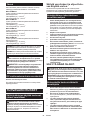
EN Cordless Impact Wrench INSTRUCTION MANUAL 5
SV Sladdlös mutterdragare BRUKSANVISNING 16
NO Batteridrevet slagskrutrekker BRUKSANVISNING 27
FI Akkukäyttöinen iskevä
mutterinväännin KÄYTTÖOHJE 38
DA Elektronisk akku slagnøgle BRUGSANVISNING 49
LV Bezvada
triecienuzgriežņatslēga LIETOŠANAS INSTRUKCIJA 60
LT Belaidis smūginis
veržliasukis NAUDOJIMO INSTRUKCIJA 72
ET Juhtmeta löökmutrivõti KASUTUSJUHEND 84
RU Аккумуляторный ударный
гайковерт РУКОВОДСТВО ПО
ЭКСПЛУАТАЦИИ 95

2
1
3
Fig.1
1
2
50%-70%
70%-100%
35%-50%
20%-35%
0%-20%
Fig.2
1
Fig.3
1
Fig.4
1
B
A
Fig.5
3
2
1
Fig.6
2
1
Fig.7
Fig.8
2

Fig.9
Fig.10
Fig.11
1
Fig.12
1
23
Fig.13
1
2
3
Fig.14
1
2
4
3
Fig.15
2
2
1
Fig.16
3

Fig.17
4

5ENGLISH
ENGLISH (Original instructions)
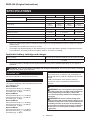
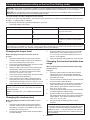
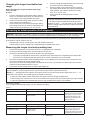
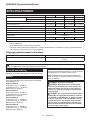
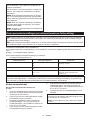
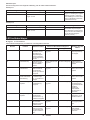
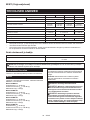
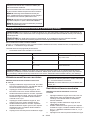
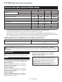
SPECIFICATIONS
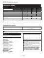
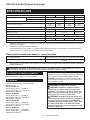
Model: DTWA070 DTWA100 DTWA140 DTWA190
Fastening capacities Standard bolt M5 - M12 M6 - M16 M8 - M16
High tensile bolt M5 - M10 M6 - M12 M8- M14
Maximum fastening torque 65 N•m 95 N•m 140 N•m 185 N•m
Torque range Approx.
5 - 40 N•m
Approx.
6 - 65 N•m
Approx.
18 - 80 N•m
Approx.
25 - 125 N•m
Square drive 9.5 mm 12.7 mm
No load speed (RPM) 0 - 2,500 min-1 0 - 2,700 min-1 0 - 2,600 min-1
Impacts per minute 0 - 3,700 min-1 0 - 3,300 min-1 0 - 3,000 min-1
Overall length 144 mm 151 mm 158 mm
Rated voltage D.C. 14.4 V
Net weight 1.1 - 1.4 kg 1.2 - 1.4 kg 1.2 - 1.5 kg 1.3 - 1.6 kg
Applicable USB cable 661432-2
• Duetoourcontinuingprogramofresearchanddevelopment,thespecicationshereinaresubjecttochange
without notice.
• Specicationsmaydierfromcountrytocountry.
• Theweightmaydierdependingontheattachment(s),includingthebatterycartridge.Thelightestandheavi-
est combination, according to EPTA-Procedure 01/2014, are shown in the table.
Applicable battery cartridge and charger
Batterycartridge BL1415N / BL1415NA / BL1430B / BL1440 / BL1460A / BL1460B
Charger DC18RC / DC18RD / DC18RE / DC18SD / DC18SE / DC18SF /
DC18SH
• Someofthebatterycartridgesandchargerslistedabovemaynotbeavailabledependingonyourregionof
residence.
WARNING: Only use the battery cartridges and chargers listed above.Useofanyotherbatterycartridges
andchargersmaycauseinjuryand/orre.
Intended use
The tool is intended for fastening bolts and nuts.
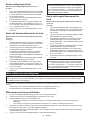
Noise
ThetypicalA-weightednoiseleveldeterminedaccord-
ing to EN62841-2-2:
Model DTWA070
Sound pressure level (LpA) : 92 dB(A)
Sound power level (LWA) : 103 dB (A)
Uncertainty(K):3dB(A)
Model DTWA100
Sound pressure level (LpA) : 93 dB(A)
Sound power level (LWA) : 104 dB (A)
Uncertainty(K):3dB(A)
Model DTWA140
Sound pressure level (LpA) : 96 dB(A)
Sound power level (LWA) : 107 dB (A)
Uncertainty(K):3dB(A)
Model DTWA190
Sound pressure level (LpA) : 95 dB(A)
Sound power level (LWA) : 106 dB (A)
Uncertainty(K):3dB(A)
NOTE: The declared noise emission value(s) has
been measured in accordance with a standard test
methodandmaybeusedforcomparingonetoolwith
another.
NOTE: The declared noise emission value(s)
mayalsobeusedinapreliminaryassessmentof
exposure.
WARNING: Wear ear protection.
WARNING: The noise emission during actual
use of the power tool can dier from the declared
value(s) depending on the ways in which the
tool is used especially what kind of workpiece is
processed.
WARNING: Be sure to identify safety mea-
sures to protect the operator that are based on an
estimation of exposure in the actual conditions of
use (taking account of all parts of the operating
cycle such as the times when the tool is switched
o and when it is running idle in addition to the
trigger time).

6ENGLISH
Vibration
The vibration total value (tri-axial vector sum) deter-
mined according to EN62841-2-2:
Model DTWA070
Work mode: impact tightening of fasteners of the maxi-
mumcapacityofthetool
Vibration emission (ah) : 9.0 m/s2
Uncertainty(K):1.5m/s2
Model DTWA100
Work mode: impact tightening of fasteners of the maxi-
mumcapacityofthetool
Vibration emission (ah) : 8.5 m/s2
Uncertainty(K):1.5m/s2
Model DTWA140
Work mode: impact tightening of fasteners of the maxi-
mumcapacityofthetool
Vibration emission (ah) : 10.0 m/s2
Uncertainty(K):1.5m/s2
Model DTWA190
Work mode: impact tightening of fasteners of the maxi-
mumcapacityofthetool
Vibration emission (ah) : 10.5 m/s2
Uncertainty(K):1.5m/s2
NOTE: The declared vibration total value(s) has been
measured in accordance with a standard test method
andmaybeusedforcomparingonetoolwithanother.
NOTE:Thedeclaredvibrationtotalvalue(s)mayalso
beusedinapreliminaryassessmentofexposure.
WARNING: The vibration emission during
actual use of the power tool can dier from the
declared value(s) depending on the ways in which
the tool is used especially what kind of workpiece
is processed.
WARNING: Be sure to identify safety mea-
sures to protect the operator that are based on an
estimation of exposure in the actual conditions of
use (taking account of all parts of the operating
cycle such as the times when the tool is switched
o and when it is running idle in addition to the
trigger time).
EC Declaration of Conformity
For European countries only
TheECdeclarationofconformityisincludedasAnnexA
to this instruction manual.
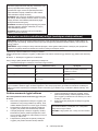
SAFETY WARNINGS
General power tool safety warnings
WARNING: Read all safety warnings, instruc-
tions, illustrations and specications provided
with this power tool. Failure to follow all instructions
listedbelowmayresultinelectricshock,reand/or
seriousinjury.
Save all warnings and instruc-
tions for future reference.
Theterm"powertool"inthewarningsreferstoyour
mains-operated(corded)powertoolorbattery-operated
(cordless) power tool.
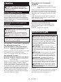
Cordless impact wrench safety warnings
1. Hold the power tool by insulated gripping
surfaces, when performing an operation
where the fastener may contact hidden wiring.
Fastenerscontactinga"live"wiremaymake
exposed metal parts of the power tool "live" and
could give the operator an electric shock.
2. Wear ear protectors.
3. Check the impact socket carefully for wear,
cracks or damage before installation.
4. Hold the tool rmly.
5. Keep hands away from rotating parts.
6. Do not touch the impact socket, bolt, nut or the
workpiece immediately after operation.They
maybeextremelyhotandcouldburnyourskin.
7. Always be sure you have a rm footing.
Be sure no one is below when using the tool in
high locations.
8. The proper fastening torque may dier
depending upon the kind or size of the bolt.
Check the torque with a torque wrench.
9. Make sure there are no electrical cables, water
pipes, gas pipes etc. that could cause a hazard
if damaged by use of the tool.
SAVE THESE INSTRUCTIONS.
WARNING:
DO NOT let comfort or familiarity
with product (gained from repeated use) replace strict
adherence to safety rules for the subject product.
MISUSE or failure to follow the safety rules stated in this
instruction manual may cause serious personal injury.
Important safety instructions for
battery cartridge
1.
Before using battery cartridge, read all instruc-
tions and cautionary markings on (1) battery
charger, (2) battery, and (3) product using battery.
2.
Do not disassemble or tamper with the battery car-
tridge.Itmayresultinare,excessiveheat,orexplosion.
3. If operating time has become excessively
shorter, stop operating immediately. It may
result in a risk of overheating, possible burns
and even an explosion.
4.
If electrolyte gets into your eyes, rinse them out
with clear water and seek medical attention right
away. It may result in loss of your eyesight.
5. Do not short the battery cartridge:
(1) Do not touch the terminals with any con-
ductive material.
(2) Avoid storing battery cartridge in a con-
tainer with other metal objects such as
nails, coins, etc.
(3) Do not expose battery cartridge to water
or rain.

7ENGLISH
A battery short can cause a large current
ow, overheating, possible burns and even a
breakdown.
6. Do not store and use the tool and battery car-
tridge in locations where the temperature may
reach or exceed 50 °C (122 °F).
7. Do not incinerate the battery cartridge even if
it is severely damaged or is completely worn
out. The battery cartridge can explode in a re.
8. Do not nail, cut, crush, throw, drop the battery
cartridge, or hit against a hard object to the
battery cartridge.Suchconductmayresultina
re,excessiveheat,orexplosion.
9. Do not use a damaged battery.
10. The contained lithium-ion batteries are subject
to the Dangerous Goods Legislation require-
ments.
Forcommercialtransportse.g.bythirdparties,
forwarding agents, special requirement on pack-
aging and labeling must be observed.
For preparation of the item being shipped, consult-
ing an expert for hazardous material is required.
Pleasealsoobservepossiblymoredetailed
national regulations.
Tapeormaskoopencontactsandpackupthe
batteryinsuchamannerthatitcannotmove
around in the packaging.
11. When disposing the battery cartridge, remove
it from the tool and dispose of it in a safe
place. Follow your local regulations relating to
disposal of battery.
12. Use the batteries only with the products
specied by Makita. Installing the batteries to
non-compliantproductsmayresultinare,exces-
siveheat,explosion,orleakofelectrolyte.
13. If the tool is not used for a long period of time,
the battery must be removed from the tool.
14. During and after use, the battery cartridge may
take on heat which can cause burns or low
temperature burns. Pay attention to the han-
dling of hot battery cartridges.
15. Do not touch the terminal of the tool imme-
diately after use as it may get hot enough to
cause burns.
16. Do not allow chips, dust, or soil stuck into the
terminals, holes, and grooves of the battery
cartridge.Itmayresultinpoorperformanceor
breakdownofthetoolorbatterycartridge.
17. Unless the tool supports the use near
high-voltage electrical power lines, do not use
the battery cartridge near high-voltage electri-
cal power lines.Itmayresultinamalfunctionor
breakdownofthetoolorbatterycartridge.
18. Keep the battery away from children.
SAVE THESE INSTRUCTIONS.
CAUTION: Only use genuine Makita batteries.
Use of non-genuine Makita batteries, or batteries that
havebeenaltered,mayresultinthebatterybursting
causingres,personalinjuryanddamage.Itwill
alsovoidtheMakitawarrantyfortheMakitatooland
charger.
Tips for maintaining maximum
battery life
1. Charge the battery cartridge before completely
discharged. Always stop tool operation and
charge the battery cartridge when you notice
less tool power.
2.
Never recharge a fully charged battery cartridge.
Overcharging shortens the battery service life.
3.
Charge the battery cartridge with room tempera-
ture at 10 °C - 40 °C (50 °F - 104 °F). Let a hot
battery cartridge cool down before charging it.
4. When not using the battery cartridge, remove
it from the tool or the charger.
5. Charge the battery cartridge if you do not use
it for a long period (more than six months).
FUNCTIONAL
DESCRIPTION
CAUTION: Always be sure that the tool is
switched o and the battery cartridge is removed
before adjusting or checking function on the tool.
Installing or removing battery
cartridge
CAUTION: Always switch o the tool before
installing or removing of the battery cartridge.
CAUTION: Hold the tool and the battery car-
tridge rmly when installing or removing battery
cartridge.Failuretoholdthetoolandthebattery
cartridgermlymaycausethemtoslipoyourhands
andresultindamagetothetoolandbatterycartridge
andapersonalinjury.
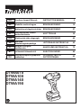
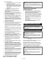
►Fig.1: 1. Red indicator 2. Button 3.Batterycartridge
Toremovethebatterycartridge,slideitfromthetool
while sliding the button on the front of the cartridge.
Toinstallthebatterycartridge,alignthetongueonthe
batterycartridgewiththegrooveinthehousingandslip
itintoplace.Insertitallthewayuntilitlocksinplace
withalittleclick.Ifyoucanseetheredindicatoras
showninthegure,itisnotlockedcompletely.
CAUTION: Always install the battery cartridge
fully until the red indicator cannot be seen. If not,
itmayaccidentallyfalloutofthetool,causinginjuryto
youorsomeonearoundyou.
CAUTION: Do not install the battery cartridge
forcibly.Ifthecartridgedoesnotslideineasily,itis
notbeinginsertedcorrectly.
Tool / battery protection system
Thetoolisequippedwithatool/batteryprotectionsys-
tem.Thissystemautomaticallycutsopowertothe
motortoextendtoolandbatterylife.Thetoolwillauto-
maticallystopduringoperationifthetoolorbatteryis
placed under one of the following conditions:

8ENGLISH
Overload protection
Whenthebatteryisoperatedinamannerthatcauses
ittodrawanabnormallyhighcurrent,thetoolautomat-
icallystopswithoutanyindication.Inthissituation,turn
thetooloandstoptheapplicationthatcausedthetool
to become overloaded. Then turn the tool on to restart.
Overheat protection
Whenthetool/batteryisoverheated,thetoolstops
automatically.Inthissituation,letthetool/batterycool
before turning the tool on again.
Overdischarge protection
Whenthebatterycapacityisnotenough,thetoolstopsautomatically.
Inthiscase,removethebatteryfromthetoolandchargethebattery.
Checking the remaining battery
capacity (BL1460A)
►Fig.2: 1. Indicator lamps 2. Check button
NOTE: Depending on the conditions of use and the
ambienttemperature,theindicationmaydierslightly
fromtheactualcapacity.
When charging
Whenthechargingbegins,therst(farleft)indicatinglamp
begins to blink. Then, as charging proceeds, the other lamps
light,oneaftertheother,toindicatethebatterycapacity.
NOTE: If the indicator lamp does not turn on or blink
whencharging,thebatterymaybefaulty.Inthiscase,
askyourlocalservicecenter.
When using
When the tool is switched on, the lamps will light to
indicatetheremainingbatterycapacity.Whenthetoolis
switchedo,thelightgoesoutafterapprox.5seconds.
When pushing the check button with the tool switched
o,theindicatorlampsturnonforapprox.5secondsto
showbatterycapacity.
If the orange lamp blinks, the tool stops because of little
remainingbatterycapacity(Auto-stopmechanism).Chargethe
batterycartridgeoruseachargedbatterycartridgeatthistime.
Whenthetoolisusedwiththebatterythathasnotbeen
usedforalongtimeandisswitchedon,nolampsmay
light up. The tool stops because of little remaining bat-
terycapacityatthistime.Chargethebatteryproperly.
Switch action
►Fig.3: 1. Switch trigger
CAUTION: Before installing the battery car-
tridge into the tool, always check to see that the
switch trigger actuates properly and returns to
the "OFF" position when released.
Tostartthetool,simplypulltheswitchtrigger.Tool
speedisincreasedbyincreasingpressureontheswitch
trigger. Release the switch trigger to stop.
NOTE:Thetoolautomaticallystopsifyoukeeppull-
ing the switch trigger for about 3 minutes.
Lighting up the front lamp
►Fig.4: 1. Lamp
CAUTION: Do not look in the light or see the
source of light directly.
Pull the switch trigger to light up the lamp. The lamp
keeps on lighting while the switch trigger is being pulled.
Thelampgoesoutapproximately10secondsafter
releasing the switch trigger.
NOTE:Useadryclothtowipethedirtothelensof
the lamp. Be careful not to scratch the lens of lamp, or
itmaylowertheillumination.
Reversing switch action
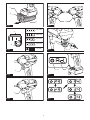
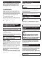
►Fig.5: 1. Reversing switch lever
CAUTION: Always check the direction of
rotation before operation.
CAUTION: Use the reversing switch only after
the tool comes to a complete stop. Changing the
directionofrotationbeforethetoolstopsmaydam-
age the tool.
CAUTION: When not operating the tool,
always set the reversing switch lever to the neu-
tral position.
This tool has a reversing switch to change the direction
of rotation. Depress the reversing switch lever from the
A side for clockwise rotation or from the B side for coun-
terclockwise rotation.
When the reversing switch lever is in the neutral posi-
tion, the switch trigger cannot be pulled.
Changing the parameter setting on
the computer
Youcanconguredetailedsettingofthetoolwiththe
applicationsoftware"MakitaIndustryToolSettings".
Install the application software on the computer and
connect the tool to the computer with a USB cable.
Refertotheinstructionmanualof"MakitaIndustryTool
Settings"fordetailsonconguration.
►Fig.6: 1. USB port 2. USB cover 3. USB cable
NOTICE: Make sure that the USB cover closed
when fastening.
NOTE: When the reversing switch lever is depressed
in the clockwise rotation, the indicator shows the
setting of clockwise rotation.
When the reversing switch lever is depressed in the
counterclockwise rotation, the indicator shows the
setting of counterclockwise rotation.
NOTE: Use preset number as a guideline. To keep
the fastening torque, number of impacts changes
automaticallyaccordingtoremainingbatterycapacity.
NOTE: Use the makita genuine USB cable to con-
nectyourcomputertothetool.Refertothesection
"SPECIFICATIONS".
NOTE: For the application software, please contact
Makita sales representative.

9ENGLISH
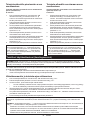
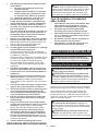
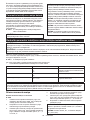
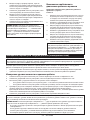
Changing the parameter setting on the tool (Field Setting mode)
NOTICE:
Thisfunctionisavailablebydefault.IfyouhavedisabledtheFieldSettingmodeonthecomputer,enable
thisfunctionbeforehand.Refertotheinstructionmanualof"MakitaIndustryToolSettings"forhowtocongure.
NOTICE:IftheFieldSettingmodeisdisabled,makingsettingsonthetoolisnotavailable.Whenyoupressthe
settingbutton,thevaluessetonthetoolaredisplayedinorder.
Thecurrentsettingnumberisdisplayedontheindicator.
Everytimeyoupressthesettingbutton,theindicatorshowstorquelevel,rundownlevel,workabletimerange,and“Ad”.
►Fig.7: 1. Setting button 2. Indicator
Youcanchangethefollowingparametersettingsonyourtool:
• Auto-stop setting / Free mode
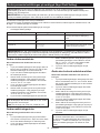
Setting item Display on the indicator Description
Torque level 01 - 40
FF
OP
The torque level at which the Tightening
Auto Stop mode works
Rundown level L1 - L7
OP
Thesensitivityofthefastenerseating
Workable time range Lo: 0.1 - 9.9
HI: 0.1 - 9.9
-.-
The shortest/longest duration of the rota-
tionwhenyoucontinuetopulltheswitch
trigger.
NOTICE:If"OP"(LooseningAutoStopmode)isdisplayedontheindicator,torquelevelsettingandrundown
level setting is not available. In this case, change the mode to Tightening Auto Stop mode, and then set the torque
levelandrundownlevelonthecomputerusing"MakitaIndustryToolSettings".
Changing the torque level
When changing the torque level from 23 to 34
►Fig.8
1. Press the setting button several times until the
indicator shows 2-digit number which stands for
the current setting of the torque level.
2. Press and hold the setting button until the number
in the tens place starts blinking.
3. Setthenumberinthetensplacebypressingthe
settingbuttonbriey.Everytimeyoupressthe
setting button, the indicator shows the number
from"0"to"4"and"F"inacycle.
4. Press and hold the setting button until the number
in the ones place starts blinking.
5.
Setthenumberintheonesplacebypressingthesetting
buttonbriey.Everytimeyoupressthesettingbutton,the
indicatorshowsthenumberfrom"0"to"9"and"F"inacycle.
6.
Press and hold the setting button for a few seconds.
NOTE:Ifyouarenotsurewhichtorquelevelissuit-
ableforyourwork,set"FF"sothatthetooloperates
in the Free mode.
NOTE:Ifyouinput"00","FF"isdisplayedinsteadof
"00".
Changing the rundown level
When changing the rundown level from L1 to L2
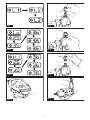
►Fig.9
1. Press the setting button several times until the
indicator shows 2 characters beginning with "L"
followedbyanumber.Thisstandsforthecurrent
setting of the rundown level.
2. Press and hold the setting button until the indica-
tor starts blinking.
3. Settherundownlevel.Everytimeyoupressthe
setting button, the indicator shows from "L1" to
"L7"inacycle.Thelowestrundownlevelis"L1"
and "L7" is the highest.
4.
Press and hold the setting button for a few seconds.
Changing the shortest workable time
range
When changing the shortest workable time range
from 2.5 to 3.6
►Fig.10
1. Press the setting button several times until the
indicatorshows"Lo"andnumberalternatively.
This stands for the current setting of the shortest
workable time range.
2. Press and hold the setting button until the number
in the ones place starts blinking.
3. Setthenumberintheonesplacebypressingthe
settingbuttonbriey.Everytimeyoupressthe
setting button, the indicator shows the number
from"0"to"9"inacycle.
4. Press and hold the setting button until the number
in the decimal place starts blinking.
5. Setthenumberinthedecimalplacebypressing
thesettingbuttonbriey.Everytimeyoupressthe
setting button, the indicator shows the number
from"0"to"9"inacycle.
6. Press and hold the setting button for a few
seconds.
NOTE:Whenyousetthevaluesmallerthan"0.1"for
the shortest workable time range, the indicator shows
"-.-" and the shortest workable time range becomes
disabled. To input "-.-", set the value to "0.9", and then
press the setting button when the number in the ones
place is blinking.

10 ENGLISH
Changing the longest workable time
range
When changing the longest workable time range
from 2.5 to 3.6
►Fig.11
1.
Press the setting button several times until the indicator
shows"HI"andnumberalternatively.Thisstandsforthe
current setting of the longest workable time range.
2. Press and hold the setting button until the number
in the ones place starts blinking.
3.
Setthenumberintheonesplacebypressingthesetting
buttonbriey.Everytimeyoupressthesettingbutton,the
indicatorshowsthenumberfrom"0"to"9"inacycle.
4. Press and hold the setting button until the number
in the decimal place starts blinking.
5. Setthenumberinthedecimalplacebypressing
thesettingbuttonbriey.Everytimeyoupressthe
setting button, the indicator shows the number
from"0"to"9"inacycle.
6. Press and hold the setting button for a few
seconds.
NOTE:Whenyousetthevaluelargerthan"9.9"for
the longest workable time range, the indicator shows
"-.-" and the longest workable time range becomes
disabled. To input "-.-", set the value to "9.9", and then
press the setting button when the number in the ones
place is blinking.
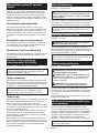
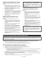
Measuring an actual operation (Self-diagnosis)
NOTICE:
Thisfunctionisavailablebydefault.IfyouhavedisabledtheFieldSettingmodeonthecomputer,enable
thisfunctionbeforehand.Refertotheinstructionmanualof"MakitaIndustryToolSettings"forhowtocongure.
Youcanmeasurethetorquelevelandoperatingtimeofanactualoperationbyoperatingthetool.Measuredtorque
level and time can be used for such as;
• Reproducing a torque control technic of a well-skilled worker and;
• A time reference for the setting of the shortest/longest workable time range.
Measuring the torque level and operating time
1. Pressthesettingbuttonseveraltimesuntil"Ad."isdisplayedontheindicator.
2. Press and hold the setting button until the indicator shows "Ch".
3. Performtheoperationthatyouwanttomeasuretheoperatingtime.
• Ifyouhaveconguredthetorquelevel,operatethetooluntilitstopsintheTighteningAutoStopmode.
• Ifyouhavenotconguredthetorquelevel(Freemode),operatethetoolasnecessary.
4. Checkthemeasuredresult.Pressthesettingbuttononcetodisplaytheactualtorquelevel,andpressitone
moretimetodisplaytheactualoperatingtime.
Everytimeyoupressthesettingbutton,theindicatorshows"Ch",thenumberofactualtorquelevel,andthe
numberofactualoperatingtimeinacycle.
5. Press and hold the setting button to exit the Self-diagnosis.
NOTE:TheTighteningAutoStopmodeworksevenintheSelf-diagnosis.Ifyouwanttomeasurethetorquelevel
without limitation, set the torque level "FF" (Free mode) and perform the procedures above.
NOTE:If"--"isdisplayedontheindicator,theimpactdidnotworkorthetorquelevelishigherthan40.If"-.-"is
displayedintheindicator,theoperatingtimeexceeded9.9seconds.
• In case the impact did not work: Remeasure the torque level with longer workable time.
•
In case the torque level is higher than 40: The tool cannot measure the torque level. Use the tool with higher torque range if available.
• In case the operating time exceeded 9.9 seconds, the workable time range is not available.
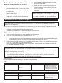
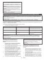
Measuring example:
Ifyoucongurethefollowingsetting,youcanreadthetoolstatus.
Case 1
Setting item Tool setting Measured result Diagnosis
Torque level 23 20 Thetoolhasstoppedbythe
setting of the longest workable
time range (3.5 sec.) before
it reaches the setting of the
Tightening Auto Stop mode
(torque level 23).
Workable time range shortest: 2.5 sec.
longest: 3.5 sec.
3.5
Case 2
Setting item Tool setting Measured result Diagnosis
Torque level 23 23 Thetoolhasstoppedbythe
Tightening Auto Stop mode
(torque level 23) before it
reaches the setting of longest
workable time range (3.5 sec.).
Workable time range shortest: 2.5 sec.
longest: 3.5 sec.
3

11 ENGLISH
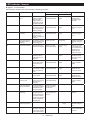
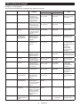
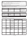
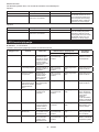
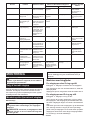
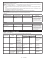
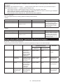
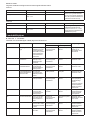
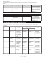
LED indicator / beeper
►Fig.12: 1. LED indicator
LED indicator / beeper on the tool shows the following functions.
Alarm No. Function Status of the tool Status of the LED indicator/beeper Action to be taken
LED indicator Beeper
E0 Batteryinstallation
error
Ifthebatterycar-
tridge is installed
with the switch
trigger pulled, the
tool stops to avoid
unintentional start.
Blinks in red and
greenalternatively.
A series of long
beeps
Installthebattery
cartridge with
the switch trigger
released.
E1 Auto-stop Thebatterypower
became low and it is
time to replace the
batterycartridge.
Blinks in red and
greenalternatively.
A series of long
beeps
Replacethebattery
withfullycharged
one.
E2 Anti-reset of
controller
Thebatteryvoltage
dropped abnor-
mallyforsome
reason, and the tool
stopped.
Blinks in red and
greenalternatively.
A series of long
beeps
Replacethebattery
withfullycharged
one.
E3 Auto-stop with low
remainingbattery
capacity
Thebatterypoweris
almost used up and
the tool stopped.
Lights up in red. A long beep Replacethebattery
withfullycharged
one.
E4 Overload protection The tool was over-
loaded and stopped.
Blinks in red and
greenalternatively.
A series of long
beeps
Remove the cause
of overload, and
then restart the tool.
Askyourlocal
Makita Service
Center for repair.
E5 Overheat protection Tool's controller
heated up abnor-
mallyandthetool
stopped.
Blinksinredquickly. A series of long
beeps
Removethebattery
cartridge immedi-
atelyandcoolthe
tool down.
E6 Motor lock The motor has been
locked. At this time,
the tool does not
work.
Blinks in red and
greenalternatively.
A series of long
beeps
Release the switch
trigger and pull it
again.
E7 Motor failure The tool detected a
motor failure. At this
time, tool does not
work.
Blinks in red and
greenalternatively.
A series of long
beeps
Askyourlocal
Makita Service
Center for repair.
E8 Switch failure The tool detected a
switch failure.
Blinks in red and
greenalternatively.
A series of long
beeps
Askyourlocal
Makita Service
Center for repair.
E9 Alarm for a long
period of use
The tool has been
turned on for a long
time (Approx. 3
minutes).
Blinks in red and
greenalternatively.
A long beep Release the switch
trigger and pull it
again.
-Auto-stop with fas-
tening completion
The preset fasten-
ing torque has been
achieved and the
tool has stopped.
Lights up in green
forapproximately
one second.
– –
-Alarmforinsucient
fastening
The preset fas-
tening torque has
not been achieved
because the switch
trigger was released
before completing
the fastening.
Lights up in red for
approximatelyone
second.
A long beep Retighten the
fastener.
-Alarm for limit of the
fasteningcapacity
–Blinksinredquickly. A series of long
beeps
Replacethebattery
withfullycharged
one.
-Maintenance alarm The number of drive
has been reached to
yourpresetnumber
for the maintenance.
Blinksinyellow. –Reset the alarm
with the application
software.

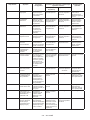
12 ENGLISH
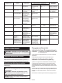
Alarm No. Function Status of the tool Status of the LED indicator/beeper Action to be taken
LED indicator Beeper
-Alarm for no com-
munication with
the PC
No data commu-
nication while the
tool is connected to
the PC.
Blinksinyellow. –Restart the appli-
cation software and
re-connect the USB
cable.
-Indication that the
tool can communi-
cate with the PC
The tool is con-
nected to the PC
and able to commu-
nicate with.
Blinks in green. – –
-Check for the lamp
and beeper (when
thebatterycartridge
is installed)
The tool performs
the operation test
for the LED indicator
(green/red), light,
and beeper.
The LED indicator
lights up in green
and then red. After
that, the light turns
on for a while.
Aseriesofvery
short beeps
–
ASSEMBLY
CAUTION: Always be sure that the tool is
switched o and the battery cartridge is removed
before carrying out any work on the tool.
Selecting correct impact socket
Alwaysusethecorrectsizeimpactsocketforboltsandnuts.
An incorrect size impact socket will result in inaccurate and
inconsistent fastening torque and/or damage to the bolt or nut.
Installing or removing impact socket
Optional accessory
CAUTION: Make sure that the impact socket
and the mounting portion are not damaged before
installing the impact socket.
CAUTION: After inserting the impact socket,
make sure that it is rmly secured. If it comes out,
do not use it.
NOTE:Thewayofimpactsocketinstallationvaries
dependingonthetypeofthesquaredriveonthetool.
Tool with the ring spring
For impact socket without O-ring and pin
►Fig.13:
1. Impact socket 2. Square drive 3. Ring spring
Push the impact socket onto the square drive until it locks into place.
Toremovetheimpactsocket,simplypullito.
For impact socket with O-ring and pin
►Fig.14: 1. Impact socket 2. O-ring 3. Pin
Move the O-ring out of the groove in the impact socket
and remove the pin from the impact socket. Fit the
impact socket onto the square drive so that the hole in
the impact socket is aligned with the hole in the square
drive.
Insert the pin through the hole in the impact socket and
square drive. Then return the O-ring to the original posi-
tion in the impact socket groove to retain the pin.
To remove the impact socket, follow the installation
procedures in reverse.
Tool with the detent pin
►Fig.15: 1. Impact socket 2. Hole 3. Square drive
4. Detent pin
Align the hole in the side of the impact socket with the
detent pin on the square drive and push the impact
socket onto the square drive until it locks into place. Tap
itlightlyifrequired.
Toremovetheimpactsocket,simplypullito.Ifitis
hard to remove, depress the detent pin while pulling the
impact socket.
Installing hook
Optional accessory
The hook is useful to hang the tool. Install the hook to
theholesonthetoolbody.
►Fig.16: 1. Hook 2. Hole
OPERATION
CAUTION: Always insert the battery cartridge
all the way until it locks in place.Ifyoucanseethe
red indicator on the upper side of the button, it is not
lockedcompletely.Insertitfullyuntiltheredindicator
cannotbeseen.Ifnot,itmayaccidentallyfalloutof
thetool,causinginjurytoyouorsomeonearound
you.
CAUTION:Holdthetoolrmlyandplacethe
impact socket over the bolt or nut. Turn the tool on
and fasten for the proper fastening time.
CAUTION:Ifthetoolisoperatedcontinuously
untilthebatterycartridgehasdischarged,allowthe
tool to rest for 15 minutes before proceeding with a
freshbatterycartridge.
CAUTION: Pressing excessively on the tool
will not speed up the drilling. In fact, this excessive
pressurewillonlyservetodamagethetipofyourdrill
bit, decrease the tool performance and shorten the
service life of the tool.
CAUTION: Always secure workpieces in a
vise or similar hold-down device.

13 ENGLISH
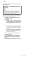
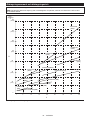
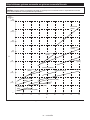
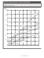
►Fig.17
Theproperfasteningtorquemaydierdependingupon
the kind or size of the bolt, the material of the workpiece
to be fastened, etc.
NOTICE:Whenfasteningsmallbolts,carefully
adjustpressureontheswitchtriggersothatthebolt
is not damaged.
NOTICE: Hold the tool pointed straight at the bolt
or nut.
NOTICE:Excessivefasteningtorquemaydamage
thebolt/nutorimpactsocket.Beforestartingyour
job,alwaysperformatestoperationtodeterminethe
properfasteningtimeforyourboltornut.
Thefasteningtorqueisaectedbyawidevarietyof
factorsincludingthefollowing.Afterfastening,always
check the torque with a torque wrench.
1. Whenthebatterycartridgeisdischargedalmost
completely,voltagewilldropandthefastening
torque will be reduced.
2. Impact socket
• Failure to use the correct size impact socket
will cause a reduction in the fastening torque.
• A worn impact socket (wear on the hex end
or square end) will cause a reduction in the
fastening torque.
3. Bolt
• Eventhoughthetorquecoecientandthe
class of bolt are the same, the proper fasten-
ingtorquewilldieraccordingtothediame-
ter of bolt.
• Even though the diameters of bolts are the
same,theproperfasteningtorquewilldier
accordingtothetorquecoecient,theclass
of bolt and the bolt length.
4. Theuseoftheuniversaljointortheextension
bar somewhat reduces the fastening force of the
impactwrench.Compensatebyfasteningfora
longer period of time.
5. The manner of holding the tool or the material
ofdrivingpositiontobefastenedwillaectthe
torque.
6. Operating the tool at low speed will cause a reduc-
tion in the fastening torque.

14 ENGLISH
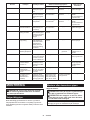
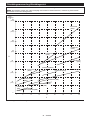
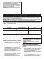
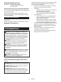
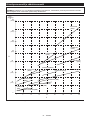
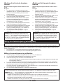
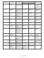
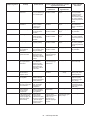
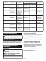
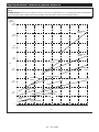
Fastening torque and torque level
NOTE:ThisreferencevalueismeasuredbythemeasurementconditionsspeciedbyMakita.
NOTE:Theactualvaluemaydieraccordingtocircumstancesofthefasteners,materials,andfasteningmethod.
Perform a test drive before actual work.
(1224)
(816)
(408)
(1428)
140
(1020)
100
(612)
60
(204)
(M6)
(M6)
DTWA070
DTWA100
(M10)
DTWA190
(M8)DTWA100
(M8)
DTWA070
(M10)DTWA070
(M10)DTWA100
(M10)DTWA140
(M12)
DTWA190
(M12)
DTWA140
(M12)
DTWA100
(M14)
DTWA190
(M8)
DTWA140
510152025303
54
0
1
2
20
120
80
40
N m
(kgf cm)
1
0
1. Torque level 2. Fastening torque

15 ENGLISH
MAINTENANCE
CAUTION: Always be sure that the tool is
switched o and the battery cartridge is removed
before attempting to perform inspection or
maintenance.
NOTICE: Never use gasoline, benzine, thinner,
alcohol or the like. Discoloration, deformation or
cracks may result.
To maintain product SAFETY and RELIABILITY,
repairs,anyothermaintenanceoradjustmentshould
beperformedbyMakitaAuthorizedorFactoryService
Centers,alwaysusingMakitareplacementparts.
OPTIONAL
ACCESSORIES
CAUTION: These accessories or attachments
are recommended for use with your Makita tool
specied in this manual.Theuseofanyother
accessories or attachments might present a risk of
injurytopersons.Onlyuseaccessoryorattachment
for its stated purpose.
Ifyouneedanyassistanceformoredetailsregard-
ingtheseaccessories,askyourlocalMakitaService
Center.
• Hook
• Protector (Blue, Red, Yellow, Green, Clear)
• BatteryProtectorforBL1460A
• BatteryProtectorforBL1415NA
• Makitagenuinebatteryandcharger
• USB cable
NOTE:Someitemsinthelistmaybeincludedinthe
toolpackageasstandardaccessories.Theymay
dierfromcountrytocountry.

16 SVENSKA
SVENSKA (Originalinstruktioner)
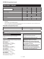
SPECIFIKATIONER
Modell: DTWA070 DTWA100 DTWA140 DTWA190
Åtdragningskapaciteter Standardbult M5 - M12 M6 - M16 M8 - M16
Höghållfasta bultar M5 - M10 M6 - M12 M8 - M14
Maximalt åtdragningsmoment 65 N•m 95 N•m 140 N•m 185 N•m
Vridmomentsintervall Ca 5 - 40 N•m Ca 6 - 65 N•m
Ca 18 - 80 N•m
Ca 25 - 125 N•m
Fyrkantigdrivtapp 9,5 mm 12,7 mm
Hastighet utan belastning (RPM) 0 - 2 500 min-1 0 - 2 700 min-1 0 - 2 600 min-1
Slag per minut 0 - 3 700 min-1 0 - 3 300 min-1 0 - 3 000 min-1
Total längd 144 mm 151 mm 158 mm
Märkspänning 14,4 V likström
Nettovikt 1,1 - 1,4 kg 1,2 - 1,4 kg 1,2 - 1,5 kg 1,3 - 1,6 kg
Tillämplig USB-kabel 661432-2
• Pågrundavvårtpågåendeprogramförforskningochutvecklingkandessaspecikationerändrasutanföregå-
ende meddelande.
• Specikationerkanvarieramellanolikaländer.
• Viktenkanvarieraberoendepåtillbehören,inklusivebatterikassett.Denlättasteochdentyngstakombinatio-
nen enligt EPTA-procedur 01/2014 visas i tabellen.
Tillgänglig batterikassett och laddare
Batterikassett BL1415N / BL1415NA / BL1430B / BL1440 / BL1460A / BL1460B
Laddare DC18RC / DC18RD / DC18RE / DC18SD / DC18SE / DC18SF /
DC18SH
• Vissaavbatterikassetternaochladdarnapålistanovankanskeintennstillgängligaidinregion.
VARNING: Använd endast batterikassetter och laddare från listan ovan. Användning av andra batterikas-
setter och laddare kan orsaka personskada och/eller brand.
Avsedd användning
Verktygetäravsettföråtdragningavbultarochmuttrar.
Buller
Den normala bullernivån för A-belastning är bestämd
enligt EN62841-2-2:
Modell DTWA070
Ljudtrycksnivå(LpA) : 92 dB (A)
Ljudeektnivå(LWA) : 103 dB (A)
Mättolerans(K):3dB(A)
Modell DTWA100
Ljudtrycksnivå(LpA) : 93 dB (A)
Ljudeektnivå(LWA) : 104 dB (A)
Mättolerans(K):3dB(A)
Modell DTWA140
Ljudtrycksnivå(LpA) : 96 dB (A)
Ljudeektnivå(LWA) : 107 dB (A)
Mättolerans(K):3dB(A)
Modell DTWA190
Ljudtrycksnivå(LpA) : 95 dB (A)
Ljudeektnivå(LWA) : 106 dB (A)
Mättolerans(K):3dB(A)
OBS: Det deklarerade bullervärdet har uppmätts i
enlighet med standardtestmetoden och kan användas
förjämförandetavenmaskinmedenannan.
OBS: Det deklarerade bulleremissionsvärdet kan
också användas i en preliminär bedömning av expo-
nering för vibration.
VARNING: Använd hörselskydd.
VARNING: Bulleremissionen under faktisk
användning av maskinen kan skilja sig från det
deklarerade värdet, beroende på hur maskinen
används och särskilt vilken typ av arbetsstycke
som behandlas.
VARNING: Var noga med att identiera säker-
hetsåtgärder för att skydda användaren, vilka är
grundade på en uppskattning av graden av expo-
nering för vibrationer under de faktiska använd-
ningsförhållandena, (ta, förutom avtryckartiden,
med alla delar av användarcykeln i beräkningen,
som till exempel tiden då maskinen är avstängd
och när den går på tomgång).

17 SVENSKA
Vibration
Det totala vibrationsvärdet (treaxlad vektorsumma)
bestämt enligt EN62841-2-2:
Modell DTWA070
Arbetsläge: maskinens maximala kapacitet för
slagåtdragning
Vibrationsemission (ah) : 9,0 m/s2
Mättolerans(K):1,5m/s2
Modell DTWA100
Arbetsläge: maskinens maximala kapacitet för
slagåtdragning
Vibrationsemission (ah) : 8,5 m/s2
Mättolerans(K):1,5m/s2
Modell DTWA140
Arbetsläge: maskinens maximala kapacitet för
slagåtdragning
Vibrationsemission (ah) : 10,0 m/s2
Mättolerans(K):1,5m/s2
Modell DTWA190
Arbetsläge: maskinens maximala kapacitet för
slagåtdragning
Vibrationsemission (ah) : 10,5 m/s2
Mättolerans(K):1,5m/s2
OBS:
Det deklarerade totala vibrationsvärdet har
uppmätts i enlighet med standardtestmetoden och kan
användasförjämförandetavenmaskinmedenannan.
OBS:
Det deklarerade totala vibrationsvärdet kan också använ-
das i en preliminär bedömning av exponering för vibration.
VARNING: Vibrationsemissionen under fak-
tisk användning av maskinen kan skilja sig från
det deklarerade värdet, beroende på hur maski-
nen används och särskilt vilken typ av arbetss-
tycke som behandlas.
VARNING: Var noga med att identiera säker-
hetsåtgärder för att skydda användaren, vilka är
grundade på en uppskattning av graden av expo-
nering för vibrationer under de faktiska använd-
ningsförhållandena, (ta, förutom avtryckartiden,
med alla delar av användarcykeln i beräkningen,
som till exempel tiden då maskinen är avstängd
och när den går på tomgång).
EG-försäkran om överensstämmelse
Gäller endast inom EU
EG-försäkran om överensstämmelse inkluderas som
bilaga A till denna bruksanvisning.
SÄKERHETSVARNINGAR
Allmänna säkerhetsvarningar för maskiner
VARNING: Läs alla säkerhetsvarningar, anvis-
ningar, illustrationer och specikationer som
medföljer det här maskinen.Underlåtenhetattfölja
instruktionerna kan leda till elstötar, brand och/eller
allvarliga personskador.
Spara alla varningar och instruk-
tioner för framtida referens.
Termen”maskin”somangesivarningarnahänvisartill
din eldrivna maskin (sladdansluten) eller batteridrivna
maskin (sladdlös).
Säkerhetsvarningar för sladdlös
mutterdragare
1. Håll maskinen i de isolerade handtagen om det
nns risk för att skruvdragaren kan komma i
kontakt med en dold elkabel. Skruvdragare som
kommerikontaktmeden”strömförande”kabel
kanfåsinablottlagdametalldelar”strömförande”,
vilket kan ge användaren en elektrisk stöt.
2. Använd hörselskydd.
3. Kontrollera krafthylsan noga före användning,
så att den inte är sliten, sprucken eller skadad.
4. Håll stadigt i maskinen.
5. Håll händerna på avstånd från roterande delar.
6. Rör inte momenthylsan, bulten, muttern eller
arbetsstycket direkt efter arbetet. De kan vara
extremt varma och orsaka brännskador.
7. Se till att alltid ha ordentligt fotfäste.
Se till att ingen står under dig när maskinen
används på hög höjd.
8. Rätt åtdragningsmoment kan variera beroende
på bultens typ eller storlek. Kontrollera åtdrag-
ningsmomentet med en momentnyckel.
9. Se till att det inte nns några elkablar, vatten-
rör, gasledningar etc. som kan orsaka fara om
de skadas av verktyget.
SPARA DESSA ANVISNINGAR.
VARNING:
GLÖM INTE att också fortsättnings-
vis strikt följa säkerhetsanvisningarna för maski-
nen även efter att du blivit van att använda den.
Vid FELAKTIG HANTERING av maskinen eller om
inte säkerhetsanvisningarna i denna bruksanvis-
ning följs kan följden bli allvarliga personskador.
Viktiga säkerhetsanvisningar för
batterikassetten
1.
Innan batterikassetten används ska alla instruk-
tioner och varningsmärken på (1) batteriladda-
ren, (2) batteriet och (3) produkten läsas.
2.
Montera inte isär eller mixtra med batterikassetten.
Det kan leda till brand, överdriven värme eller explosion.
3.
Om drifttiden blivit avsevärt kortare ska använd-
ningen avbrytas omedelbart. Det kan uppstå över-
hettning, brännskador och t o m en explosion.
4. Om du får elektrolyt i ögonen ska de sköljas
med rent vatten och läkare uppsökas omedel-
bart. Det nns risk för att synen förloras.
5. Kortslut inte batterikassetten.
(1) Rör inte vid polerna med något strömfö-
rande material.
(2) Undvik att förvara batterikassetten till-
sammans med andra metallobjekt som
t.ex. spikar, mynt o.s.v.
(3) Skydda batteriet mot vatten och regn.

18 SVENSKA
En batterikortslutning kan orsaka ett
stort strömöde, överhettning, brand och
maskinhaveri.
6. Förvara och använd inte verktyget och batteri-
kassetten på platser där temperaturen kan nå
eller överstiga 50 °C.
7. Bränn inte upp batterikassetten även om
den är svårt skadad eller helt utsliten.
Batterikassetten kan explodera i öppen eld.
8. Spika inte i, krossa, kasta, tappa eller slå bat-
terikassetten mot hårda föremål.Dylikahän-
delser kan leda till brand, överdriven värme eller
explosion.
9. Använd inte ett skadat batteri.
10. De medföljande litiumjonbatterierna är föremål
för kraven i gällande lagstiftning för farligt
gods.
Förkommersiellatransporter(avt.ex.tredjeparter
somspeditionsrmor)måstedesärskildatrans-
portkrav som anges på emballaget och etiketter
iakttas.
För att förbereda den produkt som ska avsändas
krävs att du konsulterar en expert på riskmaterial.
Var också uppmärksam på att det i ditt land kan
nnasytterligareföreskrifterattfölja.
Tejpaöverellermaskerablottadekontakteroch
packa batteriet på sådant sätt att det inte kan röra
sig fritt i förpackningen.
11. När batterikassetten ska kasseras måste den
tas bort från maskinen och kasseras på ett
säkert sätt. Följ lokala föreskrifter beträande
avfallshantering av batteriet.
12. Använd endast batterierna med de produkter
som specicerats av Makita. Att använda bat-
teriernamedejgodkändaprodukterkanledatill
brand, överdriven värme, explosion eller utläck-
andeelektrolyt.
13. Om maskinen inte används under en lång tid
måste batteriet tas bort från maskinen.
14. Under och efter användning kan batterikasset-
ten bli het vilket kan orsaka brännskador eller
lättare brännskador. Var uppmärksam på hur
du hanterar varma batterikassetter.
15. Vidrör inte verktygets kontakter direkt efter
användning eftersom de kan bli heta och
orsaka brännskador.
16. Låt inte isor, damm eller smuts fastna i kon-
takterna, i hål eller spår i batterikassetten. Det
kanledatilldåligprestandaellertillattverktyget
eller batterikassetten går sönder.
17. Såvida inte verktyget stöder arbeten i närheten
av högspänningsledningar får batterikassetten
inte användas i närheten av en högspännings-
ledning.Detkanledatillattverktygetellerbatteri-
kassetten går sönder eller inte fungerar korrekt.
18. Förvara batteriet utom räckhåll för barn.
SPARA DESSA ANVISNINGAR.
FÖRSIKTIGT: Använda endast äkta Makita-
batterier. Användning av oäkta Makita-batterier eller
batterier som har manipulerats kan leda till person-
och utrustningsskador eller till att batteriet fattar eld.
DetupphäverocksåMakitasgarantiförverktygetoch
laddaren.
Tips för att uppnå batteriets max-
imala livslängd
1.
Ladda batterikassetten innan den är helt urlad-
dad. Stanna alltid maskinen och ladda batterikas-
setten när du märker att maskinen blir svagare.
2. Ladda aldrig en fulladdad batterikassett.
Överladdning förkortar batteriets livslängd.
3. Ladda batterikassetten vid en rumstemperatur
på 10 °C - 40 °C. Låt en varm batterikassett
svalna innan den laddas.
4. När batterikassetten inte används ska den tas
bort från verktyget eller laddaren.
5. Ladda batterikassetten om du inte har använt
den på länge (mer än sex månader).
FUNKTIONSBESKRIVNING
FÖRSIKTIGT: Se alltid till att maskinen är
avstängd och batterikassetten borttagen innan
du justerar maskinen eller kontrollerar dess
funktioner.
Montera eller demontera batterikassetten
FÖRSIKTIGT: Stäng alltid av maskinen innan
du monterar eller tar bort batterikassetten.
FÖRSIKTIGT: Håll stadigt i maskinen och
batterikassetten när du monterar eller tar bort
batterikassetten. I annat fall kan det leda till att de
glider ur dina händer och orsakar skada på maskinen
och batterikassetten samt personskada.
►Fig.1: 1. Röd indikator 2.Knapp3. Batterikassett
Tabortbatterikassettengenomattskjutanerknap-
pen på kassettens framsida samtidigt som du drar ut
batterikassetten.
Sätt i batterikassetten genom att rikta in tungan på bat-
terikassettenmotspåretihöljetochskjutdenpåplats.
Tryckinbatterikassettenordentligttillsdenlåserfast
med ett klick. Om du kan se den röda indikatorn som
bilden visar är den inte låst ordentligt.
FÖRSIKTIGT: Sätt alltid i batterikassetten
helt tills den röda indikatorn inte längre syns. I
annatfallkandenoväntatfallaurverktygetochskada
dig eller någon annan.
FÖRSIKTIGT: Montera inte batterikassetten
med våld. Om kassetten inte lätt glider på plats är
den felinsatt.
Skyddssystem för maskinen/
batteriet
Verktygetärutrustatmedettskyddssystemförverkty-
get/batteriet.Dettasystembryterautomatisktströmmen
tillmotornförattförlängaverktygetsochbatteriets
livslängd.Verktygetstopparautomatisktunderanvänd-
ningenomverktygetellerbatteriethamnarienavföl-
jandesituationer:

19 SVENSKA
Överbelastningsskydd
Om batteriet används på ett sätt som gör att det drar onormalt
mycketströmkandetstoppasautomatisktutannågonvarning.När
dettaskerstängerduavverktygetochupphörmedarbetetsom
gjordeattverktygetöverbelastades.Startadärefterverktygetigen.
Överhettningsskydd
Närverktyget/batterietöverhettasstoppasverktyget
automatiskt.Isådantfallskadulåtaverktyget/batteriet
svalnainnandustartarverktygetigen.
Överurladdningsskydd
När batteriets kapacitet är otillräcklig stoppar maskinen auto-
matiskt. I sådant fall ska batteriet tas ur maskinen och laddas.
Kontrollera kvarvarande
batterikapacitet (BL1460A)
►Fig.2: 1. Indikatorlampor 2.Kontrollknapp
OBS: Beroende på användningsförhållanden och den
omgivandetemperaturenkanindikationenskiljasig
lätt från den faktiska batterikapaciteten.
Vid laddning
Närladdningeninledsbörjardenförsta(längsttillvänster)indika-
torlampan att blinka. Allteftersom laddningen fortgår tänds sedan
de andra lamporna en efter en för att visa batterikapaciteten.
OBS:Omindikatorlampanintetändsellerimrarvid
laddning, kan det vara fel på batteriet. Rådfråga i så
fall ditt lokala servicecenter.
Vid användning
Närmaskinenslåspålyserlampornaförattvisa
återstående batterikapacitet. När maskinen stängs av
släcksljuseteftercirka5sekunder.
Närmantryckerpåkontrollknappenmedmaskinen
avstängd, tänds indikatorlampan i ca 5 sekunder och
visar batterikapacitet.
Om den orangea lampan blinkar stannar maskinen på grund av
för låg batterikapacitet (autostoppmekanism). Ladda batterikas-
setten eller använd en laddad batterikassett vid detta tillfälle.
När maskinen används med ett batteri som inte har
använts under en längre tid, kan det hända att inga
lampor tänds när maskinen slås på. Maskinen stannar
nu på grund av för låg batterikapacitet. Ladda batteriet
ordentligt.
Avtryckarens funktion
►Fig.3: 1.Avtryckare
FÖRSIKTIGT: Innan du sätter i batterikasset-
ten i maskinen ska du kontrollera att avtryckaren
fungerar och återgår till läget ”OFF” när du släp-
per den.
Tryckinavtryckarenförattstartamaskinen.
Hastighetenökasgenomatttryckahårdarepåavtryck-
aren.Släppavtryckarenförattstoppamaskinen.
OBS:Verktygetstannarautomatisktomduhållerin
avtryckarenica3minuter.
Tända frontlampan
►Fig.4: 1. Lampa
FÖRSIKTIGT: Titta inte in i ljuset eller direkt
i ljuskällan.
Tryckpåavtryckarenföratttändalampan.Lampan
fortsätterattlysasålängeduhålleravtryckarenintryckt.
Lampan slocknar ungefär 10 sekunder efter att du har
släpptavtryckaren.
OBS: Använd en torr trasa för att torka bort smuts
från lampglaset. Var försiktig så att inte lampglaset
repaseftersomljusetdåkanblisvagare.
Reverseringsspakens funktion
►Fig.5: 1. Reverseringsspak
FÖRSIKTIGT: Kontrollera alltid rotationsrikt-
ningen före användning.
FÖRSIKTIGT: Använd endast reverseringsk-
nappen när maskinen har stoppat helt. Maskinen
kanskadasomdubyterrotationsriktningmedanden
fortfarande roterar.
FÖRSIKTIGT: Ställ alltid in reverseringsspa-
ken i neutralt läge när du inte använder maskinen.
Dennamaskinharenreverseringsknappförbyteav
rotationsriktning.Tryckinreverseringsspakenfrånsida
A för medurs rotation och från sida B för moturs rotation.
När reverseringsspaken är i neutralt läge fungerar inte
avtryckaren.
Ändra parameterinställningen på
datorn
Dukankongureradendetaljeradeinställningenför
verktygetmedprogramvaran”MakitaIndustryTool
Settings”.Installeraprogramvaranpådatornochanslut
verktygettilldatornmedenUSB-kabel.
Läsbruksanvisningentill”MakitaIndustryToolSettings”
förattsedetaljeromkongurationen.
►Fig.6: 1. USB-port 2. USB-lucka 3. USB-kabel
OBSERVERA: Se till att USB-luckan är stängd vid
fastsättning.
OBS:Närreverseringsspakenärintrycktimedurs
riktning, visar indikatorn inställningen för medurs
rotation.
Närreverseringsspakenärintrycktimotursriktning,
visar indikatorn inställningen för moturs rotation.
OBS:Användförinställtnummersomriktlinje.För
att behålla åtdragningsmomentet ändras antalet slag
automatiskt utefter återstående batterikapacitet.
OBS: Använd original-USB-kabeln från Makita
förattanslutadatorntillverktyget.Seavsnittet
”SPECIFIKATIONER”.
OBS:KontaktaMakitasförsäljareförattfåtillgångtill
programvaran.

20 SVENSKA
Ändra parameterinställningen på verktyget (läget Field Setting)
OBSERVERA: Denna funktion är tillgänglig som standard. Om du har avaktiverat läget Field Setting
(Fältinställning)pådatorn,skadenfunktionenaktiverasförst.Läsibruksanvisningentill”MakitaIndustryTool
Settings”hurdukongurerar.
OBSERVERA:OmlägetFieldSettingärinaktiverat,gårdetinteattgörainställningarpåverktyget.Närdu
tryckerpåinställningsknappenvisasiordningdevärdensomärinställdapåverktyget.
Det aktuella inställningsnumret visas på indikatorn.
Varjegångdutryckerpåinställningsknappenvisarindikatornvridmomentnivå,nedkörningsnivå,arbetsbartidoch”Ad”.
►Fig.7: 1. Inställningsknapp 2. Indikator
Dukanändraföljandeparameterinställningarpåverktyget:
• Autostoppinställning/friläge
Inställningsobjekt Visning på indikatorn Beskrivning
Vridmomentnivå 01 - 40
FF
OP
Den vridmomentnivå där läget Tightening
Auto Stop (Autostopp för åtdragning)
verkar
Nedkörningsnivå L1 - L7
OP
Känslighetenföråtdragningen
Arbetsbar tid Lo: 0.1 - 9.9
HI: 0.1 - 9.9
-.-
Den kortaste/längsta rotationstiden när du
fortsättertryckapåavtryckaren.
OBSERVERA:Om”OP”(autostopplägeförlossning)visaspåindikatorn,ärinställningavvridmomentnivåoch
nedkörningsnivå inte tillgängligt. Ändra i så fall läget till autostoppläge för åtdragning, och ställ sedan in vridmo-
mentnivåochnedkörningsnivåpådatornmedhjälpav”MakitaIndustryToolSettings”.
Ändra vridmomentnivån
När vridmomentnivån ändras från 23 till 34
►Fig.8
1. Tryckpåinställningsknappeneragångertillsindi-
katornvisarett2-sirigtnummersomstårförden
aktuella inställningen av vridmomentnivån.
2. Tryckochhållininställningsknappentillssiran
förtiotalbörjarblinka.
3. Ställinsiranförtiotalgenomatttryckakortpå
inställningsknappen.Varjegångdutryckerpå
inställningsknappen visar indikatorn numret från
”0”till”4”och”F”iencykel.
4. Tryckochhållininställningsknappentillssiran
förentalbörjarblinka.
5. Ställinsiranförentalgenomatttryckakortpå
inställningsknappen.Varjegångdutryckerpå
inställningsknappen visar indikatorn numret från
”0”till”9”och”F”iencykel.
6.
Tryckochhållininställningsknappenettparsekunder.
OBS: Om du inte är säker på vilken vridmomentnivå
somärlämpligfördittarbete,ställerduin”FF”såatt
verktygetkörsidetfrialäget.
OBS:Omduanger”00”visas”FF”iställetför”00”.
Ändra nedkörningsnivån
När nedkörningsnivån ändras från L1 till L2
►Fig.9
1.
Tryckpåinställningsknappeneragångertillsindikatorn
visar2teckensombörjarmed”L”följtavettnummer.Detta
står för den aktuella inställningen av nedkörningsnivån.
2. Tryckochhållininställningsknappentillsindika-
tornbörjarblinka.
3. Ställinnedkörningsnivån.Varjegångdutrycker
på inställningsknappen visar indikatorn numret
från”L1”till”L7”iencykel.Denlägstanedkör-
ningsnivånär”L1”och”L7”ärhögst.
4. Tryckochhållininställningsknappenettpar
sekunder.
Ändra den kortaste arbetsbara tiden
När kortast arbetsbar tid ändras från 2,5 till 3,6
►Fig.10
1. Tryckpåinställningsknappeneragångertillsindi-
katornomväxlandevisar”Lo”ochnummer.Detta
står för den aktuella inställningen av den kortaste
arbetsbara tiden.
2. Tryckochhållininställningsknappentillssiran
förentalbörjarblinka.
3. Ställinsiranförentalgenomatttryckakortpå
inställningsknappen.Varjegångdutryckerpå
inställningsknappen visar indikatorn numret från
”0”till”9”iencykel.
4. Tryckochhållininställningsknappentillssiran
fördecimalbörjarblinka.
5. Ställinsiranfördecimalgenomatttryckakort
påinställningsknappen.Varjegångdutryckerpå
inställningsknappen visar indikatorn numret från
”0”till”9”iencykel.
6. Tryckochhållininställningsknappenettpar
sekunder.
OBS:Närduställerinettvärdemindreän”0,1”för
denkortastearbetsbaratiden,visarindikatorn”-.-”
och den kortaste arbetsbara tiden blir inaktiverad. För
attmatain”-.-”sätterduvärdetpå”0,9”ochtrycker
sedanpåinställningsknappennärsiranförental
blinkar.
Sidan laddas...
Sidan laddas...
Sidan laddas...
Sidan laddas...
Sidan laddas...
Sidan laddas...
Sidan laddas...
Sidan laddas...
Sidan laddas...
Sidan laddas...
Sidan laddas...
Sidan laddas...
Sidan laddas...
Sidan laddas...
Sidan laddas...
Sidan laddas...
Sidan laddas...
Sidan laddas...
Sidan laddas...
Sidan laddas...
Sidan laddas...
Sidan laddas...
Sidan laddas...
Sidan laddas...
Sidan laddas...
Sidan laddas...
Sidan laddas...
Sidan laddas...
Sidan laddas...
Sidan laddas...
Sidan laddas...
Sidan laddas...
Sidan laddas...
Sidan laddas...
Sidan laddas...
Sidan laddas...
Sidan laddas...
Sidan laddas...
Sidan laddas...
Sidan laddas...
Sidan laddas...
Sidan laddas...
Sidan laddas...
Sidan laddas...
Sidan laddas...
Sidan laddas...
Sidan laddas...
Sidan laddas...
Sidan laddas...
Sidan laddas...
Sidan laddas...
Sidan laddas...
Sidan laddas...
Sidan laddas...
Sidan laddas...
Sidan laddas...
Sidan laddas...
Sidan laddas...
Sidan laddas...
Sidan laddas...
Sidan laddas...
Sidan laddas...
Sidan laddas...
Sidan laddas...
Sidan laddas...
Sidan laddas...
Sidan laddas...
Sidan laddas...
Sidan laddas...
Sidan laddas...
Sidan laddas...
Sidan laddas...
Sidan laddas...
Sidan laddas...
Sidan laddas...
Sidan laddas...
Sidan laddas...
Sidan laddas...
Sidan laddas...
Sidan laddas...
Sidan laddas...
Sidan laddas...
Sidan laddas...
Sidan laddas...
Sidan laddas...
Sidan laddas...
Sidan laddas...
Sidan laddas...
-
 1
1
-
 2
2
-
 3
3
-
 4
4
-
 5
5
-
 6
6
-
 7
7
-
 8
8
-
 9
9
-
 10
10
-
 11
11
-
 12
12
-
 13
13
-
 14
14
-
 15
15
-
 16
16
-
 17
17
-
 18
18
-
 19
19
-
 20
20
-
 21
21
-
 22
22
-
 23
23
-
 24
24
-
 25
25
-
 26
26
-
 27
27
-
 28
28
-
 29
29
-
 30
30
-
 31
31
-
 32
32
-
 33
33
-
 34
34
-
 35
35
-
 36
36
-
 37
37
-
 38
38
-
 39
39
-
 40
40
-
 41
41
-
 42
42
-
 43
43
-
 44
44
-
 45
45
-
 46
46
-
 47
47
-
 48
48
-
 49
49
-
 50
50
-
 51
51
-
 52
52
-
 53
53
-
 54
54
-
 55
55
-
 56
56
-
 57
57
-
 58
58
-
 59
59
-
 60
60
-
 61
61
-
 62
62
-
 63
63
-
 64
64
-
 65
65
-
 66
66
-
 67
67
-
 68
68
-
 69
69
-
 70
70
-
 71
71
-
 72
72
-
 73
73
-
 74
74
-
 75
75
-
 76
76
-
 77
77
-
 78
78
-
 79
79
-
 80
80
-
 81
81
-
 82
82
-
 83
83
-
 84
84
-
 85
85
-
 86
86
-
 87
87
-
 88
88
-
 89
89
-
 90
90
-
 91
91
-
 92
92
-
 93
93
-
 94
94
-
 95
95
-
 96
96
-
 97
97
-
 98
98
-
 99
99
-
 100
100
-
 101
101
-
 102
102
-
 103
103
-
 104
104
-
 105
105
-
 106
106
-
 107
107
-
 108
108


på andra språk
- eesti: Makita DTWA190 Kasutusjuhend
- dansk: Makita DTWA190 Brugermanual
Relaterade papper
-
Makita DTW300 Användarmanual
-
Makita BTP141Z Användarmanual
-
Makita DTW284 Användarmanual
-
-
-
-
-
Makita TW007G, TW008G Cordless Impact Wrench Användarmanual
-
-
Makita DHP485 Användarmanual