Sioux Tools VAC-FORCE 1557 Användarmanual
- Typ
- Användarmanual

1
Form ZCE671
Date 2003July29/C
Page 1 of 52
Printed In U.S.A.
INSTRUCTIONS & PARTS LIST FOR
SIOUX 1557 DRILLING MACHINE

2
Another Quality SIOUX Product
You will be rewarded by your choice of 1557, helping you produce superior holes quickly and efficiently.
Sioux is committed to providing quality products, through innovation and research to allow holes to be
produced quickly, safely, and with a minimum of effort.
Before attempting to operate your new 1557, please read all instructions first. With proper use, care, and
maintenance, your 1557 will provide you with years of effective hole drilling performance. 1557 is a patented
vacuum base attachment designed exclusively for specific air drill capacities and collar sizes. The unit allows
you to attach and drill ferrous and non-ferrous materials, plastics, composites, timber, masonry, irregular work
surfaces, and thin materials quickly and efficiently. 1557 does away with the limited, expensive, and
cumbersome ‘magnetic based’ drills. Simply attach your air drill to the unit and you are ready to drill holes
quickly, efficiently, and more importantly, with portability. 1557 weighs approximately 9.9 lb (4.5 kg) (with air
drill attached) and operates at 75-120 psi At 85 psi the unit consumes only 3.0 cfm of air. However, the air
drill consumes approximately 13 cfm of air. Best of all it runs on compressed air and
1557 does not require
any special suction/vacuum pump. Drilling holes in non-ferrous materials (copper, aluminum, stainless steel)
or irregular work surfaces (i.e. checker plate) has never been easier or more productive. 1557 also features a
safety valve. The safety valve cuts air supply to the drill when the vacuum pad is not adhered to the working
surface or if the vacuum pad suddenly breaks away from the working surface.
Gone are the days of pushing a drill; the finger pressure controls greatly reduce operator effort and fatigue.
1557 can attach to a wide range of materials that equally require a variable range of drilling pressures. With a
simple press of our revolutionary drill feed pressure control lever we enable you to easily control your drilling
pressure. We have given you the ability to control the drill pressure as it
cuts for you through materials that range from light pressure to 155 lb
(70 kilograms) force. From thin glass to plywood or from stainless
steel to aluminum, 1557 will do them all.
The choice boosts productivity. Modern day industry in
general knows that large sums of money are wasted on
work injuries, absenteeism, and fatigue. Your ergonomic
choice of 1557 is right and you will increase your
productivity.
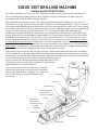
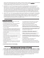
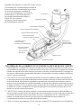
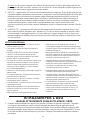
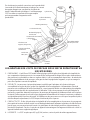
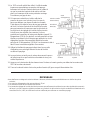
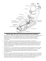
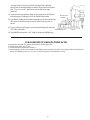
SIOUX 1557 DRILLING MACHINE
Air Cylinder
Drill Clamp
Tear Drop
Drill Feed Lever
Drill Feed Adjustment
Release Button
(Situated on left side)
Handle
Allen Key and
Allen Key Holder
(Situated on left side)
Air Supply
Control Valve
1/4" NPT Inlet
Safety Valve
Vacuum Pad
Air Drill
Supply Hose

3
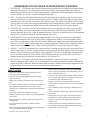
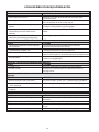
ADVANTAGES OF 1557 CAN BE CATEGORISED INTO SIX AREAS:
1. ERGONOMIC - 1557 reduces the amount of human effort required due to the lightness and user friendly
finger pressure controls. The compactness of the unit provides a more desirable direction of force in
awkward and confined positions. Two handed operation - right hand on drill handle/trigger, left hand on
the unit’s handle, encourages a correct and balanced posture.
2. SAFE - Control of the drill feed is indirect through the drill feed lever, providing a more consistent feed
rate, and removing the user from any direct torque reaction. A built-in safety valve will only supply air to
the drill once the vacuum pad is secured to the working surface. The safety valve will also cut air supply
to the air drill in the event of the vacuum pad breaking away from the working surface. Unlike a pedestal
drill, 1557 locks to the item being drilled, whereas with a pedestal drill, the work must be clamped.
3. PRODUCTIVE - Due to the even and correct drill feed force being applied to the drill, one can achieve
more rapid drilling and holes produced are straighter than those produced by hand held drills. Built in
vacuum generator gives over – (90kPa) maximum vacuum. The unit is cost efficient, as the recommended
retail price is considerably less than a similar magnetic based unit.
4. LIGHTWEIGHT- Due to the 1557 weighing approximately 9.9 lb (4.5 kg) in comparison to a magnetic
based drill that weighs 28 lb (13.0 kg) plus, time is saved between drilling. It is more portable in every
way. Time is saved when locating unit at the desired drilling point, simply due to the weight advantages.
There is no need for
heavy safety cables when operating at heights. Release button creates air pressure
under vacuum pad to provide an air cushion (hovercraft) effect to further provide ease of locating.
5. UNIQUE - The 1557 is powered only by compressed air. Swiveling of mast allows for it to produce holes
close to edges and / or corners. Vacuum pad and seal design gives excellent stability of the unit on most
surfaces for a positive and precise drilling / cutting operation. The unit can be operated underwater and
also in hazardous spark free environments (check drill manufacturer). Use of optional Curved Surface
Adapter allows unit to lock directly onto pipe down to 2 in (50 mm) O.D.
6. VERSATILITY - 1557 adheres to most surfaces and materials - ferrous, non-ferrous, composites,
masonry, fiberglass, glass, timber, etc. It can be used on thin materials and doesn’t mark or damage the
surface to which it is attached. Magnetic based drills are now so limited in their range of applications due
to the fact they can only hold onto ferrous materials of a certain thickness.
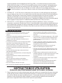
• Read ALL instructions before operating this tool.
• Use may produce flying objects.
• ALWAYS where safety goggles when operating or
repairing this tool.
• Always wear hearing protection when operating this
tool.
• For safety, top performance, and maximum durability of
parts operate at a pressure no more than 120 psi
(840kPa) or a manufacturer’s maximum recommended
pressure.
• Use safety cable when operating at heights.
• Repairs should only be carried out by suitably qualified
technicians.
• Keep hands, loose clothing, and long hair away from
rotating parts.
• Check for excessive speed or vibrations before
operating.
• Do NOT lubricate tools with flammable or volatile liquids
such as kerosene, diesel, or jet fuel.
• Do NOT carry unit by the hose.
• Do NOT remove any labels. Replace only damaged
label. Use only accessories recommended by SIOUX
and / or Drill manufacturer.
• This tool is NOT electrically insulated - NEVER use the
tool if there is any chance of coming into contact with
live electricity (e.g. inside wall cavity).
• Always use air hose & couplings with a minimum
working pressure rating at least 1.5 times the operating
pressure.
• Check hoses & fittings regularly for damage and / or
water.
• Do NOT disable or bypass any safety devices on any
equipment.
• Always turn off the air supply or disconnect the air
supply before installing, removing, or adjusting any
accessory on this tool or before performing any
maintenance.
• Inspect cutting tool for obvious defects before use.
• Use optional vacuum operated safety switch if using
electric drills in lieu of air drill.
SAFETY NOTES

4
1. Fit air drill into drill holder (with corresponding
sleeves where required). Ensure selected drill has
suitable power, torque, and speed for cutter size
and type of material. If your drill has a chuck larger
than the drill clamp hole, then the chuck will have to
be removed prior to installation of the unit. Tighten
screws in drill clamp to lock drill in place. Connect
air drill supply to air drill.
2. Select cutter or drill bit and place in drill chuck and
firmly tighten (see Drill Operator’s Manual).
3. Mark center of hole on working surface with a
center punch.
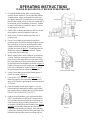
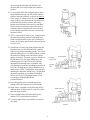
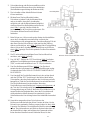
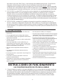
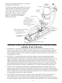
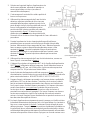
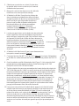
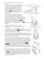
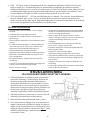
4. Using (5 mm) allen key provided, loosen both
screws at each end of the clamp and adjust so that
the cutter tip is as close as possible and the drill
clamp is positioned as low as possible on the air
cylinder as shown in
figure 1. This will improve the
distribution of the load through the unit. Tighten
screws with (5 mm) allen key.
5. When cutting holes near the edge of your working
surface, it may be necessary to move the cutting
point closer to the edge of the vacuum pad. Using
the 5 mm allen key loosen the tear drop and rotate
to desired location and tighten as shown in
figure 2.
Return cutting point to the central axis when these
holes are completed as shown in figure 3. This is
the optimum position for maximum adherence.
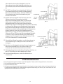
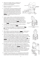
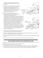
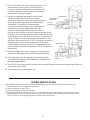
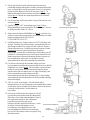
6. Using (5 mm) allen key provided, firmly tighten 3
points as shown in
figure 4.
7. Connect the 1557 1/4" NPT inlet (
figure 5) to a
filtered air supply, with a minimum bore size of (7
mm) or 5/16" and an operating air pressure range of
75-120 psi.
8. Open air supply control valve (figure 5). Any air
heard expiring to atmosphere will be coming from
the exhaust holes located in the front of the handle.
DO NOT BLOCK EXHAUST OUTLET.
9. Hold the air drill handle in your right hand and the
1557’s handle with your left hand. Ensure that the
unit’s vacuum pad and all moving air drill parts are
clear from everything including your person. Turn
on air drill. If air drill functions normally, then
do not
proceed, as the safety valve pre-test has failed -
refer to trouble shooting on Page 6. If air drill does
not function normally, then the safety valve pre-test
indicates that the safety valve is working and has
PLEASE READ CAREFULLY BEFORE OPERATING UNIT
OPERATING INSTRUCTIONS
Figure 1
Air Cylinder
Drill Clamp
3mm
Tear Drop
Figure 2
(Drill removed for clarity)
Figure 3

5
successfully disabled the drill until the unit’s
vacuum pad is securely locked to the working
surface.
10. To accurately drill in the desired location, press
the drill feed lever with your left thumb until the
drill has reached full travel, as shown in
figure 6.
Place center of cutting point in the center punch
mark. Hold the vacuum pad at an equal distance
or level with the working surface and slowly
lighten the left thumb pressure on the drill feed
lever until the vacuum pad rests evenly on the
working surface. Firmly press the vacuum pad
into the working surface to ensure vacuum seal
has taken effect.
11. 1557 is now ready to work for you. Simply turn on
the air drill and slowly press the drill feed lever
while ensuring that the center of the cutting tool
locates in the center punch mark. Now proceed to
cut your hole.
12. If drill slows or stops, then slowly lighten the left
thumb pressure on the drill feed lever, until the
drill reaches normal operating speeds. This is the
optimum drilling force. The drill feed lever controls
the amount of drilling force that the air cylinder
applies to the drill. The more you push A down on
the drill feed lever, the more drilling force you
indirectly give to the drill. When the drill feed
adjustment is screwed down (clockwise) fully,
your thumb pressure has the ability to produce up
to 155 lb (70 kilograms) of direct drilling force. In
many cases, 155 lb (70 kilograms) is too great for
obtaining the optimum drilling force. The drill feed
adjustment enables you to reduce the drilling
force from 155 lb (70 kilograms) down to 0 by
screwing the drill feed adjustment
counterclockwise.
13. Use cutting lubricant as required to prolong
cutting tool life and improve your cutting time.
14. When hole is complete, slowly lift thumb off the
drill feed lever until the cutter is clear of the hole
and then stop the drill.
15. Press release button with left index finger to
release 1557 from the working surface.
16. Turn air supply valve to off position to conserve
air supply.
Figure 4
Figure 5
1/4" NPT
Inlet
Air Supply
Control Vavle
Exhaust Hole
Figure 6
Vacuum Pad
Drill Feed Lever
Handle

6
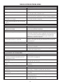
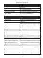
Before diagnosing problems from the following chart, check that any irregularities are prevented by ensuring that:
1. Air supply pressure is above 75psi.
2. Air supply control valve is open.
3. Drill feed adjustment is screwed down (clockwise) enough to allow correct air supply pressure to fully operate the air
cylinder, therefore allowing air cylinder to work, travel full 1.96" (50 mm) and have enough force to complete a hole.
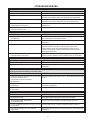
TROUBLE SHOOTING
1. Vacuum filter blocked.
2. Vacuum generator not working.
3. Vacuum seal dirty, cut or damaged.
4. Vacuum generator working but vacuum pad
won’t adhere.
5. Air pressure coming from 2mm hole located
under vacuum pad at rear.
PROBLEM – VACUUM PAD WON’T ADHERE
CAUSE SOLUTION
Remove and clean sintered filter located under vacuum pad.
Test for vacuum by placing thumb or piece of paper over
vacuum filter for suction.
Inspect seal & replace if necessary. Replacement instructions
supplied with new seal.
Check for holes in working surface. Surface porous and deep
grooves.
Replace both o-rings on safety valve.
1. Air drill not powerful enough.
2. Worn or improper cutting tools.
3. Cutter is preventing completion of hole.
4. Cylinder at end of travel.
PROBLEM – CAN’T COMPLETE A HOLE
CAUSE SOLUTION
Consider optional Reduction Gearbox, Lubricator and more
powerful air drill.
Replace with new and appropriate cutting tools.
Check cutting depth of cutter to thickness of material being
drilled.
Reposition drill clamp to allow for a further 50mm of travel.
1. Drill clamps not in correct position on air drill
and/or cylinder sleeve.
2. Cutter requires more than 1.96" (50 mm)
travel.
3. Cutter is preventing air cylinder travel.
See Section 4. under SIOUX 1557 – Operating Instructions” on
Page 4.
Reposition drill clamp to allow for a further 1.96" (50 mm) of
travel.
Check cutting depth of cutter to depth of working material.
PROBLEM – NOT ENOUGH AIR CYLINDER TRAVEL [Standard 1557 has 1.96" (50 mm) MAX. of travel]
CAUSE SOLUTION
1. Vacuum pad not adhered to working surface.
2. Air drill not working.
3. Safety valve sticking.
4. Drill feed pressure too high for drill capacity.
Safety valve is disabling the air drill until the vacuum pad is
securely adhered.
Test air drill with alternate air supply.
Disconnect 3/8" nylon hose from air drill and check for airflow
from hose when vacuum pad is securely adhered to working
surface. If airflow is not present then safety valve is sticking and
requires cleaning.
Screw drill feed adjustment up (anticlockwise) to decrease air
cylinder supply.
PROBLEM – AIR DRILL WON’T WORK
CAUSE SOLUTION
PROBLEM – AIR CYLINDER WON’T WORK
CAUSE SOLUTION
1. Damaged “0” Ring seal.
2. Cylinder damaged.
Check for air leaking from drill feed adjustment nut.
Check cylinder sleeve for dents and seals for air leaks.

7
DECLARATION OF CONFORMITY
We, Sioux Tools Inc., 250 Snap-on Drive, P.O. Box 1596, Murphy, NC, 28906, USA, declare under our sole responsibility that the products
1557
to which this declaration relates are in conformity with the following standard or standards or other normative document or documents:
EN 292 Parts 1&2
following the provisions of
98/37/EC Directive.
July 1, 2003
Murphy, North Carolina, USA
Date and place of issues
Gerald E. Seebeck
President
Sioux Tools Inc.
Name and position of issuer
Signature of issuer

8
BEDIENUNGSANLEITUNG UND TEILELISTE
FÜR SIOUX 1557 BOHRVORRICHTUNG
Ein weiteres Qualitätsprodukt von SIOUX
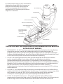
SIOUX 1557 BOHRVORRICHTUNG
Wir gratulieren Ihnen zur Wahl der 1557 Bohrvorrichtung, mit der sie qualitativ hochwertige Löcher schnell
und effizient bohren können.
Durch Innovation und Forschung liefert Sioux kompromisslose Qualitätsprodukte, mit denen Löcher schnell,
sicher und mit minimalem Aufwand gebohrt werden können.
Lesen Sie bitte zuerst die Bedienungsanleitung, bevor Sie Ihre neue 1557 Bohrvorrichtung in Betrieb
nehmen. Bei richtigem Gebrauch, Pflege und Wartung wird die 1557 Bohrvorrichtung Ihnen jahrelang beim
Bohren von Löchern behilflich sein. 1557 ist ein patentierter Vakuumbasisaufsatz, der speziell für bestimmte
Luftbohrkapazitäten und Kragengrößen entwickelt wurde. Mit dieser Vorrichtung kann in Eisen- und
Nichteisenmetallen, Kunststoffen, Kompositstoffen, Holz, Mauerwerk, unregelmäßigen Oberflächen und
dünnen Materialien schnell und effizient gebohrt werden. Die 1557 Vorrichtung macht Schluss mit in ihrer
Leistungsfähigkeit begrenzten, teuren und umständlichen "magnetbasierten" Bohrmaschinen. Setzen Sie Ihre
Druckluftbohrmaschine in diese Vorrichtung ein und schon können Sie Löcher schnell, effizient und - was am
wichtigsten ist - überall bohren. Die 1557 Vorrichtung wiegt ca. 4,5 kg (9,9 lb) (mit befestigter
Druckluftbohrmaschine) und arbeitet mit 525-840 kPa (75-120 psi). Bei 595 kPa (85 psi) verbraucht das
Gerät nur 3,0 cfm Luft. Der Druckluftbohrer verbraucht jedoch ca. 13 cfm Luft. Und was am besten ist, die
1557 Vorrichtung arbeitet mit Druckluft und
benötigt keine spezielle Saug-/Vakuumpumpe. Das Bohren von
Löchern in Nichteisenmetallen (Kupfer, Aluminium, Edelstahl) oder unregelmäßigen Flächen (z.B. in
Riffelblechen) war noch nie so einfach und produktiv. Die 1557 Vorrichtung besitzt auch ein Sicherheitsventil.
Das Sicherheitsventil unterbricht die Luftzufuhr zur Bohrmaschine, wenn das Vakuumkissen nicht auf der
Arbeitsfläche anhaftet oder plötzlich von der Arbeitsfläche fortgeschleudert wird.
Das Vorschieben der Bohrmaschine unter großem Kraftaufwand gehört der Vergangenheit an. Die bequemen
Fingersteuerungen bieten einen hohen Bedienerkomfort ohne Ermüdung. Die 1557 Vorrichtung kann für
zahlreiche Werkstoffe verwendet werden, die gleichermaßen einen weiten Bereich von Bohrandruckkräften
erfordern. Durch einfachen Druck auf unseren revolutionären Bohrvorschubsteuerungshebel kontrollieren Sie
mühelos die Bohrervorschubkraft. Durch uns haben Sie den Bohrervorschub voll im Griff und können in
Werkstoffe bohren, die entweder nur leichte Kraft bis hin zu 70 kg (155 lb) erfordern. Ob dünnes Glas,
Sperrholz, Edelstahl oder Aluminium, die 1557 Vorrichtung schafft alle Werkstoffe.

9
DIE VORTEILE DER 1557 BOHRVORRICHTUNG KÖNNEN IN SECHS BEREICHE
KATEGORISIERT WERDEN:
1. ERGONOMISCH - Die 1557 Vorrichtung reduziert den erforderlichen Kraftaufwand durch den Bediener
aufgrund ihres geringen Gewichts und der bedienerfreundlichen Fingerdrucksteuerungen. Die
Kompaktheit der Vorrichtung ermöglicht eine günstigere Kraftausrichtung in schwierigen und beengten
Positionen. Beidhändige Bedienung - die rechte Hand am Griff/Auslöser des Bohrers und die linke Hand
am Griff der Vorrichtung fördert eine korrekte und entspannte Körperhaltung.
2. SICHER - Die Steuerung des Bohrervorschubs geschieht indirekt über den Bohrervorschubhebel,
wodurch eine gleichmäßigere Vorschubrate erzielt wird und der Bediener keine direkten
Drehmomentreaktionskräfte aufnehmen muss. Ein eingebautes Sicherheitsventil sorgt dafür, dass die
Bohrmaschine nur mit Druckluft versorgt wird, wenn das Vakuumkissen einwandfrei auf der Arbeitsfläche
befestigt ist. Das Sicherheitsventil unterbricht auch die Druckluftversorgung zur Druckluftbohrmaschine,
falls das Vakuumkissen von der Arbeitsfläche fortgeschleudert wird. Anders als bei einer
Säulenbohrmaschine, bei der das Werkstück festgeklemmt werden muss, arretiert die 1557 Vorrichtung
das Bohrwerkstück.
3. PRODUKTIV - Durch die gleichmäßige und korrekte Vorschubkraft beim Bohren ist schnelleres Bohren
möglich und die Bohrlöcher sind gerader als bei Handbohrungen. Der eingebaute Vakuumerzeuger liefert
einen Unterdruck von mehr als -90 kPa. Die Vorrichtung ist kostengünstig, da der empfohlene
Verkaufspreis wesentlich geringer als eine gleichwertige magnetbasierte Maschine ist.
4. LEICHT- Da die 1557 Vorrichtung nur ca. 4,5 kg (9,9 lb) gegenüber 13,0 kg (28 lb) bei einer
magnetbasierten Bohrmaschine wiegt, sparen Sie Zeit zwischen den Bohrungen. Sie ist in jeder Hinsicht
leichter zu tragen. Allein durch die Gewichtsvorteile wird Zeit beim Ansetzen der Maschine am
Ihre Wahl bedeutet Steigerung der Produktivität. Die
Arbeitswelt von Heute weiß, dass Unsummen an
Mitteln durch Arbeitsunfälle, Abwesenheit und
Ermüdung vergeudet werden. Ihre Wahl der
ergonomischen 1557 Vorrichtung ist sinnvoll und
steigert Ihre Produktivität.
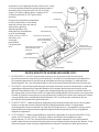
Druckluftzylinder
Bohrerklemme
Tränenformteil
Bohrervorschubhebel
Auslösetaste (linksseitig)
Bohrervorschubeinstellung
Handgriff
Steckschlüssel und
Steckschlüsselhalter
(linksseitig)
Druckluftventil
1/4" NPT-Einlass
Sicherheitsventil
Vakuumkissen
Druckluftschlauch

10
gewünschten Bohrpunkt gespart. Beim Arbeiten an erhöhten Stellen sind keine schweren Sicherheitsseile
erforderlich. Die Entriegelungstaste erzeugt Luftdruck unter dem Vakuumkissen, sodass ein
Luftkisseneffekt entsteht, der die Positionierung um so mehr erleichtert.
5. EINZIGARTIG - Die 1557 Vorrichtung wird nur durch Druckluft angetrieben. Durch Schwenken des
Mastes können Löcher nahe an Kanten und/oder Ecken gebohrt werden. Die Konstruktion des
Vakuumkissens und der Dichtung sorgt auf den meisten Oberflächen für eine ausgezeichnete Stabilität
der Vorrichtung und somit für eine einwandfreie und präzise Bohr-/Schneidwirkung. Die Vorrichtung kann
unter Wasser sowie auch in gefährlichen funkenfreien Umgebungen verwendet werden (Anweisungen
des Bohrmaschinenherstellers beachten). Durch Verwendung eines Rundflächenadapters kann die
Vorrichtung direkt auf Rohren bis zu einem Minimaldurchmesser von 50 mm (2 Zoll) verwendet werden.
6. VIELSEITIG - Die - 1557 Vorrichtung haftet auf den meisten Oberflächen und Werkstoffen - Eisenmetalle,
Nichteisenmetalle, Kompositstoffe, Mauerwerk, Fiberglas, Holz usw. Sie kann auf dünnen Werkstoffen
verwendet werden und verkratzt oder beschädigt nicht die Oberfläche, auf der sie angesetzt wird.
Magnetbasierte Bohrmaschinen eignen sich lediglich für eine begrenzte Zahl von Anwendungen, da sie
nur Eisenmetalle einer bestimmten Dicke bearbeiten können.
SICHERHEITSHINWEISE
• Bitte lesen Sie ALLE Anweisungen, bevor Sie das
Werkzeug in Gebrauch nehmen.
• Durch den Gebrauch können Teilchen herumfliegen.
• Bei Verwendung oder Instandsetzung dieses
Werkzeugs STETS eine Sicherheitsbrille tragen.
• Bei Verwendung dieses Werkzeugs stets einen
Hörschutz tragen.
• Aus Sicherheitsgründen, für beste Ergebnisse und zur
Erzielung maximaler Lebensdauer der Teile sollte die
Vorrichtung nicht mit einem Druck über 840 kPa (120
psi) bzw. über dem vom Hersteller empfohlenen Druck
betrieben werden.
• Beim Arbeiten an erhöhten Stellen ein Sicherheitsseil
verwenden.
• Reparaturen dürfen nur durch entsprechend geschultes
technisches Personal vorgenommen werden.
• Hände, lose Kleidung und langes Haar von rotierenden
Teilen entfernt halten.
• Vor dem Bohren auf überhöhte Drehzahl oder
Vibrationen kontrollieren.
• Werkstücke NICHT mit entflammbaren oder flüchtigen
Flüssigkeiten wie Kerosin, Dieselöl oder Jettreibstoff
schmieren.
• Die Vorrichtung NICHT am Schlauch tragen.
• KEINE Etiketten entfernen. Es dürfen lediglich
beschädigte Etiketten ersetzt werden. Nur Zubehör
verwenden, welches von SIOUX und/oder dem
Bohrmaschinenhersteller empfohlen ist.
• Dieses Werkzeug ist NICHT elektrisch isoliert. -
NIEMALS das Werkzeug verwenden, wenn die
Möglichkeit besteht, mit stromführenden Leitungen in
Berührung zu kommen (z.B. in einer Wandaushöhlung).
• Stets Luftschläuche und Kupplungen verwenden, die für
einen Mindestarbeitsdruck des Anderthalbfachen des
Betriebsdrucks zugelassen sind.
• Luftschläuche und Beschlagteile regelmäßig auf
Beschädigung und/oder Wasser überprüfen.
• NIEMALS irgendwelche Sicherheitsvorrichtungen an
Geräten unwirksam machen oder umgehen.
• Vor dem Befestigen, Entfernen oder Einstellen von
Zubehörteilen an diesem Werkzeug oder vor Beginn der
Wartungsarbeiten stets die Druckluftzufuhr abschalten
oder unterbrechen.
• Schneidwerkzeuge vor dem Gebrauch auf
offensichtliche Schäden untersuchen.
• Bei Verwendung einer elektrischen Bohrmaschine
anstelle einer Druckluftbohrmaschine ist der optionale
unterdruckbetätigte Sicherheitsschalter zu verwenden.
BITTE VOR DER INBETRIEBNAHME DER VORRICHTUNG SORGFÄLTIG LESEN
BEDIENUNGSANLEITUNG
1. Druckluftbohrmaschine in eine Bohrhalterung (mit entsprechenden Hülsen, soweit erforderlich) einsetzen.
Sicherstellen, dass die gewünschte Bohrmaschine genügend Leistung, Drehmoment und Drehzahl für
den zu verwendenden Bohrer und den betreffenden Werkstoff besitzt. Ist das Futter der Bohrmaschine
größer als das Bohrerklemmloch, muss das Futter vor dem Einsetzen der Vorrichtung entfernt werden.
Die Schrauben im Bohrerklemmhals festziehen, um die Bohrmaschine zu arretieren. Den
Druckluftschlauch mit der Druckluftbohrmaschine verbinden.

11
2. Schneidwerkzeug oder Bohrer auswählen und im
Spannfutter der Bohrmaschine sicher befestigen
(siehe Bedienungsanleitung der Bohrmaschine).
3. Die Lochmitte auf der Arbeitsfläche mit einem
Körner markieren.
4. Mit dem 5mm-Steckschlüssel die beiden
Schrauben an jedem Ende der Klemme lösen
und so einstellen, dass die Schneidspitze
möglichst nah und die Bohrerklemme möglichst
niedrig auf dem Druckluftzylinder positioniert ist,
wie in
Abb. 1 gezeigt. Hierdurch wird die
Lastverteilung in der Vorrichtung verbessert. Die
Schrauben mit dem 5mm-Steckschlüssel
festziehen.
5. Beim Bohren von Löchern nahe an der Kante der Arbeitsfläche
muss der Schneidpunkt eventuell näher zur Kante des
Vakuumkissens hin verlagert werden. Das tränenförmige Teil mit
dem 5mm-Steckschlüssel lösen, in die gewünschte Stellung
drehen und festziehen, wie in
Abb. 2 gezeigt. Nach Fertigstellung
dieser Löcher den Schneidpunkt zur Mittelachse zurückführen,
wie in Abb. 3 gezeigt. Dies ist die optimale Position für maximale
Haftung.
6. Die 3 Punkte mit dem beigefügten 5mm-Steckschlüssel fest
anziehen, wie in
Abb. 4 gezeigt.
7. Den 1/4"-NPT-Einlass der 1557 Vorrichtung
(Abb. 5) mit einer
gefilterten Druckluftleitung mit einer minimalen Weite von 7 mm
(5/16") und einem Betriebsdruck von 75-120 psi verbinden.
8. Das Druckluftsteuerventil öffnen (
Abb. 5). Das Geräusch
entweichender Luft stammt von den Ausströmöffnungen an der
Vorderseite des Griffs. DIE AUSSTRÖMÖFFNUNGEN NICHT
BLOCKIEREN.
9. Den Handgriff der Druckluftbohrmaschine in der rechten Hand
und den Griff der 1557 Vorrichtung in der linken Hand halten.
Sicherstellen, dass das Vakuumkissen der Vorrichtung und alle
beweglichen Teile der Druckluftbohrmaschine unbehindert sind.
Die Druckluftbohrmaschine einschalten. Wenn der
Druckluftbohrer normal funktioniert,
Vorgang nicht fortsetzen, da
der Test des Sicherheitsventils fehlgeschlagen ist. Siehe
Störungsbehebung auf Seite 6. Wenn der Druckluftbohrer nicht
normal funktioniert, bedeutet dies, dass das Sicherheitsventil
richtig arbeitet und die Bohrmaschine unterbricht, bis das
Vakuumkissen der Vorrichtung fest auf der Arbeitsfläche arretiert
ist.
10. Um präzise am gewünschten Ort zu bohren, den
Bohrervorschubhebel mit dem linken Daumen drücken, bis der
Bohrer bis zur maximalen Stellung vorgeschoben ist, wie in
Abb.
6 gezeigt. Die Mitte der Schneidspitze auf die Körnermarkierung
setzen. Das Vakuumkissen auf gleichen Abstand oder eben mit
der Arbeitsfläche halten und langsam den Daumendruck der
linken Hand auf dem Bohrervorschubhebel lösen, bis das
Abb. 1
Bohrerklemme
Druckluftzylinder
3mm
Abb. 2
Bohrmaschine zur Übersichtlichkeit entfernt
Tränenformteil
Abb. 3
Abb. 4

12
Vakuumkisten eben auf der Arbeitsfläche ruht. Das
Vakuumkissen fest auf die Arbeitsfläche drücken, um
sicherzustellen, dass die Vakuumabdichtung wirksam
ist.
11. Die 1557-Vorrichtung ist nun arbeitsbereit. Einfach die
Druckluftbohrmaschine einschalten und langsam den
Bohrervorschubhebel drücken, während die Mitte des
Schneidwerkzeugs auf der Körnermarkierung ruht.
Nun das Loch bohren.
12. Wird der Bohrer langsamer oder kommt er ganz zum
Stillstand, den linken Daumendruck auf dem
Bohrervorschubhebel langsam lösen, bis der Bohrer
wieder seine normale Drehzahl erreicht. Dies ist die
optimale Bohrkraft. Der Bohrervorschubhebel steuert
die Bohrkraft, die der Druckluftzylinder auf den Bohrer überträgt.
Je fester auf den Bohrervorschubhebel gedrückt wird, desto
mehr Bohrkraft wird indirekt auf den Bohrer ausgeübt. Wenn
die Bohrervorschubeinstellung vollständig (im Uhrzeigersinn)
eingeschraubt ist, kann durch den Daumendruck eine
Bohrkraft bis zu 70 kg (155 lb) ausgeübt werden. In vielen
Fällen sind 70 kg (155 lb) zu viel, um eine optimale Bohrkraft
zu erzielen. Durch Drehen der Bohrervorschubeinstellung
entgegen dem Uhrzeigersinn kann die Bohrkraft von 70 kg
(155 lb) bis herunter auf 0 reduziert werden.
13. Schneidöl nach Bedarf verwenden, um die Lebensdauer der
Schneidwerkzeuge zu verlängern und die Schneidzeit zu
verringern.
14. Wenn das Loch fertig gebohrt ist, den Daumen langsam vom
Bohrervorschubhebel lösen, bis der Bohrer das Loch
verlassen hat. Dann die Bohrmaschine ausschalten.
15. Die Entriegelungstaste mit dem linken Zeigefinger drücken, um
die 1557 Vorrichtung von der Arbeitsfläche zu lösen.
16. Das Druckluftventil sperren, um die Druckluftzufuhr zu
unterbrechen.
Vor der Diagnostizierung der Probleme anhand der folgenden Tabelle zunächst folgende Punkte sicherstellen:
1. Die Druckluft besitzt einen Druck über 75 psi.
2. Das Druckluftventil ist offen.
3. Die Bohrervorschubeinstellung ist ausreichend (im Uhrzeigersinn) eingeschraubt, damit der richtige Luftdruck den
Druckluftzylinder betätigen kann, sodass dieser die gesamte Auslenkung von 50 mm (1,96") vornehmen kann und
genügend Kraft zum Bohren des Lochs erhält.
STÖRUNGSBEHEBUNG
Abb. 6
Bohrervorschubhebel
Handgriff
Vakuumkissen
Abb. 5
Auslassöffnung
Druckluftventil
1/4" NPT-
Einlass

13
1. Die Druckluftbohrmaschine hat nicht
genügend Leistung.
2. Verschlissene oder ungeeignete
Schneidwerkzeuge.
3. Das Schneidwerkzeug kann das Loch nicht zu
Ende bohren.
4. Der Zylinder befindet sich am Ende der
Auslenkung.
Optionales Reduziergetriebe, Schmiervorrichtung und
leistungsfähigere Druckluftbohrmaschine verwenden.
Durch neue und passende Schneidwerkzeuge ersetzen.
Die Bohrtiefe auf die Tiefe des Arbeitswerkstoffs einstellen.
Die Bohrerklemme justieren, sodass weitere 50 mm Auslenkung
möglich ist.
PROBLEM – LOCH KANN NICHT ZU ENDE GEBOHRT WERDEN
URSACHE LÖSUNG
1. Die Bohrerklemmen befinden sich nicht in der
richtigen Position an der
Druckluftbohrmaschine und/oder
Zylinderhülse.
2. Der Bohrer erfordert mehr als 50 mm (1,96")
Auslenkung.
3. Der Bohrer verhindert die Auslenkung des
Luftzylinders.
Siehe Abschnitt 4 unter SIOUX 1557 – Bedienungsanleitung auf
Seite 4.
Die Bohrerklemme justieren, sodass weitere 50 mm (1,96")
Auslenkung möglich ist.
Die Bohrtiefe auf die Tiefe des Arbeitswerkstoffs einstellen.
PROBLEM – UNGENÜGENDE AUSLENKUNG DES DRUCKLUFTZYLINDERS [Die Standard-1557-Vorrichtung
besitzt eine maximale Auslenkung von 50 mm (1,96")]
URSACHE LÖSUNG
1. O-Ringdichtung beschädigt.
2. Zylinder beschädigt.
Prüfen, ob Luft an der Bohrervorschubeinstellmutter austritt.
Zylinderhülse auf Beulen und Dichtungen auf Luftaustritt
überprüfen.
PROBLEM – DRUCKLUFTZYLINDER ARBEITET NICHT
URSACHE LÖSUNG
1. Das Vakuumkissen haftet nicht auf der
Arbeitsfläche.
2. Die Druckluftbohrmaschine funktioniert nicht.
3. Das Sicherheitsventil klemmt.
4. Der Bohrervorschub ist zu stark für die
Leistung der Bohrmaschine.
Das Sicherheitsventil unterbricht die Druckluftbohrmaschine, bis
das Vakuumkissen einwandfrei haftet.
Die Druckluftbohrmaschine an einer anderen Druckluftleitung
überprüfen.
Den 3/8"-Nylonschlauch von der Druckluftbohrmaschine trennen
und den Luftstrom aus dem Schlauch prüfen, wenn das
Vakuumkissen sicher auf der Arbeitsfläche haftet. Ist kein
Luftstrom feststellbar, ist das Sicherheitsventil verklemmt und
muss gereinigt werden.
Die Bohrervorschubeinstellung entgegen dem Uhrzeigersinn
drehen, um die Luftzufuhr zum Druckluftzylinder zu verringern.
PROBLEM – DRUCKLUFTBOHRMASCHINE FUNKTIONIERT NICHT
URSACHE LÖSUNG
STÖRUNGSBEHEBUNG
1. Vakuumfilter verstopft.
2. Vakuumerzeuger funktioniert nicht.
3. Vakuumdichtung verschmutzt oder beschädigt.
4. Vakuumerzeuger funktioniert, aber
Vakuumkissen haftet nicht.
5. Druckluft strömt aus 2mm-Öffnung hinten unter
dem Vakuumkissen aus.
Sinterfilter unter dem Vakuumkissen entfernen und reinigen.
Zum Prüfen des Unterdrucks den Daumen oder ein Blatt Papier
über den Vakuumfilter halten und Saugwirkung kontrollieren.
Dichtung kontrollieren und nötigenfalls ersetzen. Die
Austauschanleitung ist der neuen Dichtung zu entnehmen.
Auf Löcher in der Arbeitsfläche achten. Oberfläche porös mit
tiefen Rillen.
Beide O-Ringe am Sicherheitsventil ersetzen.
PROBLEM – VAKUUMKISSEN HAFTET NICHT
URSACHE LÖSUNG

14
KONFORMITÄTSERKLÄRUNG
Wir, Sioux Tools, Inc., 250 Snap-on Drive, P.O. Box 1596, Murphy, NC, 28906, USA, erklären hiermit alleinverantwortlich, daß die Produkte
1557
auf die sich diese Erklärung bezieht, mit den Anforderungen der folgenden Standards oder Normen oder Dokumenten übereinstimmen:
EN 292 Teile 1&2
gemäß der Regelungen in
98/37/EEC Direktiven.
1. Juli 2003
Murphy, North Carolina, USA
Datum und Ort der Ausgabe
Gerald E. Seebeck
Vorsitzender
Sioux Tools Inc.
Name und Titel des Herausgebers
Unterschrift des Herausgebers

15
Otro producto SIOUX de calidad
MÁQUINA TALADRADORA SIOUX 1557
Se verá recompensado por haber elegido la unidad 1557, que le ayudará a hacer orificios de forma rápida y
eficaz.
El compromiso de Sioux es ofrecer productos de gran calidad, mediante la innovación y la investigación,
para que se puedan hacer orificios de forma rápida, segura y con el mínimo esfuerzo.
Antes de poner en funcionamiento la nueva unidad 1557, lea primero todas las instrucciones. Con el uso,
cuidado y mantenimiento adecuados, la unidad 1557 le proporcionará un gran rendimiento a la hora de hacer
orificios. La unidad 1557 es un dispositivo de sujeción neumático patentado, diseñado exclusivamente para
operaciones de perforación neumática y tamaños de anillos específicos. La unidad permite acoplarse y
perforar materiales ferrosos y no ferrosos, plásticos, materiales compuestos, madera, mampostería,
superficies irregulares y materiales de poco grosor de forma rápida y eficaz. La unidad 1557 pone fin a las
perforaciones ‘de tipo eléctrico’, que son muy limitadas, caras e incómodas. Simplemente acople el taladro
neumático a la unidad y ya estará preparado para hacer orificios de forma rápida y eficaz, y lo que es más
importante, con gran facilidad de transporte. La unidad 1557 pesa aproximadamente 9,9 libras (4,5 kg.) (con
el taladro neumático acoplado) y funciona a 75-120 psi. A 85 psi, la unidad consume sólo 3,0 cfm de aire. Sin
embargo, el taladro neumático consume aproximadamente 13 cfm de aire. Pero lo mejor es que funciona con
aire comprimido y
la unidad 1557 no requiere una bomba de vacío/aspiración especial. Hacer orificios en
materiales no ferrosos (cobre, aluminio, acero inoxidable) o en superficies irregulares (por ejemplo, una
chapa estriada) nunca ha resultado tan sencillo ni tan productivo. La unidad 1557 también incorpora una
válvula de seguridad. Esta válvula corta el suministro de aire en el taladro cuando la ventosa en vacío no se
encuentra adherida a la superficie de trabajo o si la ventosa se desprende de ésta de manera imprevista.
Ya han pasado los días en que se tenía que empujar el taladro con fuerza; los controles de presión
accionados con el dedo reducen considerablemente el esfuerzo y el cansancio del operario. La unidad 1557
se puede acoplar a una gran variedad de materiales que, de igual modo, requieren un grado variable en la
presión de perforación. Con una simple presión en nuestra innovadora palanca de control de la presión de
alimentación del taladro, le facilitamos el cómodo control de la presión de perforación. Con esta herramienta
le ofrecemos la capacidad de controlar la presión de perforación en distintos materiales, desde una ligera
presión hasta una fuerza de 155 lb (70 kilogramos). Desde vidrio fino hasta contrachapado o desde acero
INSTRUCCIONES Y PIEZAS PARA LA
MÁQUINA TALADRADORA SIOUX 1557

16
inoxidable hasta aluminio, la unidad 1557 puede con todo.
Con esta elección, su productividad se elevará de
forma considerable. La industria de hoy en día es
consciente en general de la cantidad de
recursos que se malgastan por el cansancio,
el absentismo y los accidentes laborales.
Ha acertado completamente al elegir la
unidad 1557 por su diseño
ergonómico y por el aumento de la
productividad que le supondrá.
LAS VENTAJAS DE LA UNIDAD 1557 SE PUEDEN CLASIFICAR EN SEIS GRUPOS:
1. ERGONÓMICAS: La unidad 1557 reduce la cantidad de esfuerzo humano requerido por el poco peso y
por la facilidad de manejo de sus controles de presión accionados con el dedo. Lo compacto de la unidad
permite una mejor dirección de la fuerza en posiciones incómodas y de reducido tamaño. Su manejo con
dos manos, la derecha en el mango/gatillo del taladro y la izquierda en el asa de la unidad, posibilita una
postura correcta y equilibrada.
2. SEGURIDAD: El control de la alimentación del taladro es indirecto mediante la palanca de alimentación,
lo que proporciona una velocidad de alimentación más constante y evita que el usuario sufra una fuerza
de reacción directa. Una válvula de seguridad incorporada sólo suministrará aire al taladro cuando la
ventosa en vacío esté fijada a la superficie de trabajo. La válvula cortará también el suministro de aire en
el taladro neumático en caso de que la ventosa se desprenda de la superficie de trabajo. A diferencia de
un taladro con soporte, la unidad 1557 se ajusta a la pieza que se va a perforar; mientras que con un
taladro con soporte, se debe fijar la pieza.
3. PRODUCTIVAS: Debido a la fuerza constante y correcta de la alimentación que se aplica al taladro, se
puede conseguir una perforación más rápida y los orificios efectuados son más rectos que los producidos
con taladros accionados a mano. El generador de vacío incorporado da más de – (90kPa) de vacío
máximo. La unidad resulta económica, ya que el precio recomendado de venta al público es
considerablemente inferior a una unidad similar de tipo eléctrico.
4. PESO: Por el peso aproximado de 9,9 lb (4,5 kg.) de la unidad 1557 en comparación con los taladros de
Cilindro de aire
Abrazadera del taladro
Tuerca en forma de lágrima
Palanca de alimentación del taladro
Ajuste de alimentación del talaro
Botón de desbloqueo
(situado en el lateral izquierdo)
Asa
Llave Allen y soporte
para llaves Allen
(situado en el lateral izquierdo)
Válvula de control del
suministro de aire
Boca de entrada
NPT de 1/4"
Válvula de seguridad
Ventosa en vacío
Manguera de
alimentación del
taladro neumático

17
• Lea TODAS las instrucciones antes de utilizar esta
herramienta.
• Su uso puede originar que se desprendan objetos.
• Lleve SIEMPRE anteojos de seguridad cuando utilice o
repare esta herramienta.
• Siempre lleve protección para los oídos cuando utilice
esta herramienta.
• Para mayor seguridad, un mejor rendimiento y la
máxima duración de las piezas, utilice la unidad a una
presión no superior a 120 psi (840 kPa) o a la presión
máxima recomendada por el fabricante.
• Utilice el cable de seguridad cuando se trabaje en
altura.
• Las reparaciones sólo deben realizarlas técnicos
capacitados.
• No acerque las manos, ropa suelta ni el pelo largo a las
piezas giratorias.
• Compruebe si existe una velocidad o vibraciones
excesivas antes de utilizarla.
• NO lubrique las herramientas con líquidos inflamables o
volátiles, como queroseno, diesel o combustible de
motor a reacción.
NOTAS SOBRE SEGURIDAD
tipo eléctrico que pesan 28 lb (13 kg.), se ahorra tiempo entre distintas perforaciones. Es más fácil de
transportar y ahorra tiempo a la hora de colocar la unidad en el punto de perforación elegido,
simplemente por las ventajas que supone su ligero peso. No se necesitan
pesados cables de seguridad
en trabajos que se desarrollen en altura. El botón de desbloqueo crea presión de aire bajo la ventosa en
vacío para generar un efecto de colchón de aire, con lo que se consigue una mejor fijación de la unidad.
5. EXCLUSIVAS: La unidad 1557 funciona sólo con aire comprimido. La capacidad giratoria del brazo le
permite realizar orificios en zonas próximas a bordes y esquinas. La ventosa en vacío y su diseño
hermético ofrecen una excelente estabilidad a la unidad en la mayoría de superficies, con lo que se
consigue una operación de corte y perforación de precisión. La unidad se puede utilizar debajo del agua
y en zonas peligrosas donde no se puedan producir chispas (consulte con el fabricante del taladro). El
uso del Adaptador de superficies curvas opcional permite fijar la unidad directamente en tubos de hasta 2
pulg. (50 mm) de diámetro exterior.
6. VERSATILIDAD: La unidad 1557 se adhiere a la mayoría de superficies y materiales: ferrosos, no
ferrosos, compuestos, mampostería, fibra de vidrio, vidrio, madera, etc. Se puede usar en materiales de
poco grosor sin marcar ni dañar la superficie donde se acople. Actualmente, los taladros de tipo eléctrico
son tan limitados en sus aplicaciones por el hecho de que sólo pueden fijarse en materiales ferrosos o de
cierto grosor.
• NO transporte la unidad por la manguera.
• NO quite ninguna etiqueta. Reemplace sólo las etiquetas
deterioradas. Utilice sólo los accesorios recomendados
por SIOUX y / o por el fabricante del taladro.
• Esta herramienta NO está aislada eléctricamente:
NUNCA use la herramienta si hay alguna posibilidad de
entrar en contacto con electricidad en carga (por
ejemplo, dentro de la cavidad de un muro o pared).
• Utilice siempre la manguera de aire y los acoplamientos
con una presión efectiva mínima al menos 1,5 veces
superior a la presión de funcionamiento.
• Compruebe con regularidad si existen desperfectos y /
o agua en las mangueras y en los acoplamientos.
• NO inutilice ni ignore los dispositivos de seguridad en
ningún equipo.
• Desactive o desconecte siempre el suministro de aire
antes de montar, extraer o ajustar cualquier accesorio
en esta herramienta o antes de realizar cualquier
operación de mantenimiento.
• Revise la herramienta de corte en busca de defectos
LEA CON ATENCIÓN ANTES DE UTILIZAR LA UNIDAD
INSTRUCCIONES DE FUNCIONAMIENTO
1. Coloque el taladro neumático en el soporte del taladro (con sus correspondientes manguitos donde sea
necesario). Asegúrese de que el taladro que elija tiene la potencia, la torsión y la velocidad adecuadas
para el tamaño del cortador y el tipo de material. Si el taladro tiene un portabrocas mayor que el orificio
de la abrazadera del taladro, deberá extraer el portabrocas antes de instalar la unidad. Apriete los
tornillos de la abrazadera del taladro para ajustar el taladro. Conecte el suministro de aire al taladro
neumático.

18
2. Seleccione el cortador y la broca, colóquelos en el
portabrocas y apriételos firmemente (consulte el
manual del usuario del taladro).
3. Marque el centro del orificio en la superficie de
trabajo con un punzón.
4. Con la llave allen (5 mm) que se proporciona, afloje
los dos tornillos a cada extremo de la abrazadera y
ajuste de forma que la punta del cortador quede lo
más próxima posible y la abrazadera quede lo más
bajo posible en el cilindro de aire, como se ve en la
figura 1. Así, se mejorará la distribución de la carga
a través de la unidad. Apriete los tornillos con la
llave allen (5 mm).
5. Cuando se hagan orificios cerca del borde de la superficie de
trabajo, puede ser necesario mover el punto de corte más cerca
del borde de la ventosa en vacío. Con la llave allen de 5 mm,
afloje la tuerca en forma de lágrima y gire hasta llegar al punto
deseado y apriétela, como se ve en la
figura 2. Vuelva el punto de
corte al eje central cuando haya finalizado estos orificios, como se
ve en la
figura 3. Ésta es la posición óptima de mayor adherencia.
6. Con la llave allen (5 mm) que se proporciona, apriete con firmeza
los 3 puntos que se muestran en la
figura 4.
7. Conecte la boca de entrada NPT de 1/4" de la unidad 1557 (
figura
5) a un suministro de aire filtrado, con un tamaño mínimo de
calibre de 7 mm o de 5/16" y un rango de presión de aire efectiva
de 75-120 psi.
8. Abra la válvula de control del suministro de aire (
figura 5). Cualquier fuga de
aire que salga provendrá de los orificios de escape situados en la parte
delantera del asa. NO BLOQUEE LA SALIDA DE ESCAPE.
9. Sostenga el mango del taladro con la mano derecha y el asa de la unidad
1557 con la izquierda. Asegúrese de que la ventosa en vacío de la unidad y
todas las piezas móviles del taladro neumático estén alejadas de todo, incluida
su persona. Encienda el taladro. Si el taladro funciona normalmente,
no
continúe, puesto que significa que ha fallado la prueba previa de la válvula de
seguridad; consulte la sección de resolución de problemas en la página 6. Si
el taladro neumático no funciona normalmente, la prueba previa indica que la
válvula de seguridad está funcionando y que ha bloqueado el taladro hasta
que la ventosa en vacío de la unidad esté bien fijada a la superficie de trabajo.
10. Para taladrar con precisión en el lugar deseado, presione la palanca de
alimentación del taladro con el pulgar izquierdo hasta que el taladro alcance
su recorrido completo, como se ve en la
figura 6. Coloque el centro del punto
de corte en la marca realizada con el punzón. Mantenga la ventosa en vacío a
una distancia o nivel uniforme con la superficie de trabajo y aminore
lentamente la presión del pulgar izquierdo en la palanca de alimentación del
taladro hasta que la ventosa quede de manera uniforme en la superficie de
trabajo. Presione con firmeza la ventosa en vacío contra la superficie de
trabajo para que tenga efecto el cierre hermético.
11. La unidad 1557 ya está lista para su uso. Simplemente encienda el taladro
neumático y presione suavemente la palanca de alimentación mientras se
asegura de que el centro de la herramienta de corte se sitúa en la marca
Cilindro de aire
Abrazadera
del taladro
Figura 1
3mm
Figura 2
(Se ha quitado el taladro para mayor
claridad)
Tuerca en forma
de lágrima
Figura 1
Figura 4

19
realizada con el punzón. Continúe para realizar el
orificio.
12. Si el taladro se ralentiza o se detiene, aminore
lentamente la presión del pulgar izquierdo en la
palanca de alimentación del taladro hasta que el
taladro alcance la velocidad normal de
funcionamiento; es decir, la fuerza de perforación
óptima. La palanca de alimentación controla la
cantidad de fuerza de perforación que aplica el
cilindro de aire al taladro. Cuanto más presione
sobre la palanca de alimentación del taladro,
mayor fuerza de perforación ejerce indirectamente
sobre el taladro. Cuando el ajuste de alimentación
del taladro está totalmente enroscado (en el
sentido de las agujas del reloj), la presión ejercida por
el pulgar tiene la capacidad de generar hasta 155 lb
(70 kilogramos) de fuerza de perforación directa. En
muchos casos, 155 lb (70 kilogramos) es demasiado
para obtener la fuerza de perforación óptima. El ajuste
de alimentación del taladro permite reducir la fuerza de
perforación de 155 lb (70 kilogramos) a 0
desenroscando el ajuste de alimentación en el sentido
opuesto a las agujas del reloj.
13. Utilice lubricante tantas veces como sea necesario
para prolongar la vida útil de la herramienta de corte y
mejorar así el tiempo de corte.
14. Una vez realizado el orificio, levante suavemente el
pulgar de la palanca hasta que el cortador haya salido
del orificio y pare el taladro.
15. Pulse el botón de desbloqueo con el dedo índice
izquierdo para separar la unidad 1557 de la superficie
de trabajo.
16. Deje la válvula de suministro de aire en la posición de
desconexión para conservar el suministro de aire.
Antes de diagnosticar el problema a partir de la tabla siguiente, compruebe lo siguiente para evitar cualquier anomalía:
1. La presión del suministro de aire es superior a 75 psi.
2. La válvula de control del suministro de aire está abierta.
3. El ajuste de alimentación del taladro está lo suficientemente enroscado (en el sentido de las agujas del reloj) para
permitir una correcta presión del suministro de aire con el fin de que el cilindro de aire funcione completamente, que
pueda realizar el recorrido completo de 1,96" (50 mm) y tenga fuerza suficiente para realizar un orificio.
RESOLUCIÓN DE PROBLEMAS
Figura 5
Válvula de control del
suministro de aire
Orificio de escape
Boca de
entrada NPT
de 1/4"
Figura 6
Palanca de
alimentación
del taladro
Asa
Válvula de control del
suministro de aire

20
RESOLUCIÓN DE PROBLEMAS
La válvula de seguridad bloquea el taladro neumático hasta que la
ventosa no se adhiera firmemente.
Pruebe el taladro con un suministro de aire alternativo.
Desconecte la manguera de nilón de 3/8" del taladro neumático y
compruebe el flujo de aire de la manguera cuando la ventosa en
vacío se encuentre firmemente adherida a la superficie de
trabajo. Si no hay flujo de aire, significa que la válvula está
bloqueada y requiere su limpieza.
Desenrosque el ajuste de alimentación del taladro (en el sentido
opuesto a las agujas del reloj) para disminuir el suministro del
cilindro de aire.
Considere la caja de velocidades reductora y un lubricador
opcionales y un taladro neumático de más potencia.
Reemplácelas por herramientas de corte nuevas y más
apropiadas.
Compare la profundidad de corte con el grosor del material que
se pretende perforar.
Vuelva a colocar la abrazadera del taladro para permitir un
recorrido de 50 mm.
1. El taladro neumático no tiene potencia
suficiente.
2. Herramientas de corte desgastadas o
incorrectas.
3. El cortador impide la realización de un orificio.
4. El cilindro se encuentra al final del recorrido.
PROBLEMA: NO SE PUEDE REALIZAR UN ORIFICIO
CAUSA SOLUCIÓN
1. Las abrazaderas no están en la posición
correcta en el taladro neumático y/o en el
manguito del cilindro.
2. El cortador requiere más de 1,96" (50 mm) de
recorrido.
3. El cortador impide el recorrido del cilindro de
aire.
Consulte la sección 4. en “Instrucciones de funcionamiento” de
SIOUX 1557 en la página 4.
Vuelva a colocar la abrazadera del taladro para permitir un
recorrido de 1,96" (50 mm).
Compare la profundidad de corte con la profundidad del material
de trabajo.
PROBLEMA: NO HAY SUFICIENTE RECORRIDO EN EL CILINDRO DE AIRE [La unidad estándar 1557 tiene
un recorrido de 1,96" (50 mm) MÁX.]
CAUSA SOLUCION
1. La junta anular está dañada.
2. El cilindro está dañado.
Compruebe si existe pérdida de aire en la tuerca de ajuste de
alimentación del taladro.
Compruebe si existen marcas o juntas en el manguito del cilindro
en busca de escapes de aire.
PROBLEMA: EL CILINDRO DE AIRE NO FUNCIONA
CAUSA SOLUCIÓN
1. La ventosa en vacío no se acopla a la
superficie de trabajo.
2. El taladro neumático no funciona.
3. La válvula de seguridad está bloqueada.
4. La presión de alimentación del taladro es
demasiado alta para su capacidad.
PROBLEMA: EL TALADRO NEUMÁTICO NO FUNCIONA
CAUSA SOLUCIÓN
1. El filtro de vacío está bloqueado.
2. El generador de vacío no funciona.
3. El cierre hermético está sucio, roto o dañado.
4. El generador de vacío funciona pero la ventosa
en vacío no se acopla.
5. Sale presión de aire del orificio de 2 mm
situado bajo la ventosa en vacío, en la parte
trasera.
Extraiga y limpie el filtro sinterizado ubicado bajo la ventosa en
vacío.
Compruebe la aspiración del vacío colocando el pulgar o un
trozo de papel sobre el filtro de vacío.
Revise el cierre y reemplácelo, si es necesario. Las
instrucciones de uso vendrán en el nuevo cierre que adquiera.
Compruebe si hay orificios en la superficie de trabajo. Desbaste
las ranuras porosas y profundas.
Reemplace los dos aros tóricos de la válvula de seguridad.
PROBLEMA: LA VENTOSA EN VACÍO NO SE ACOPLA
CAUSA SOLUCIÓN
Sidan laddas...
Sidan laddas...
Sidan laddas...
Sidan laddas...
Sidan laddas...
Sidan laddas...
Sidan laddas...
Sidan laddas...
Sidan laddas...
Sidan laddas...
Sidan laddas...
Sidan laddas...
Sidan laddas...
Sidan laddas...
Sidan laddas...
Sidan laddas...
Sidan laddas...
Sidan laddas...
Sidan laddas...
Sidan laddas...
Sidan laddas...
Sidan laddas...
Sidan laddas...
Sidan laddas...
Sidan laddas...
Sidan laddas...
Sidan laddas...
Sidan laddas...
Sidan laddas...
Sidan laddas...
Sidan laddas...
Sidan laddas...
-
 1
1
-
 2
2
-
 3
3
-
 4
4
-
 5
5
-
 6
6
-
 7
7
-
 8
8
-
 9
9
-
 10
10
-
 11
11
-
 12
12
-
 13
13
-
 14
14
-
 15
15
-
 16
16
-
 17
17
-
 18
18
-
 19
19
-
 20
20
-
 21
21
-
 22
22
-
 23
23
-
 24
24
-
 25
25
-
 26
26
-
 27
27
-
 28
28
-
 29
29
-
 30
30
-
 31
31
-
 32
32
-
 33
33
-
 34
34
-
 35
35
-
 36
36
-
 37
37
-
 38
38
-
 39
39
-
 40
40
-
 41
41
-
 42
42
-
 43
43
-
 44
44
-
 45
45
-
 46
46
-
 47
47
-
 48
48
-
 49
49
-
 50
50
-
 51
51
-
 52
52


Sioux Tools VAC-FORCE 1557 Användarmanual
- Typ
- Användarmanual
på andra språk
- italiano: Sioux Tools VAC-FORCE 1557 Manuale utente
- español: Sioux Tools VAC-FORCE 1557 Manual de usuario
- Deutsch: Sioux Tools VAC-FORCE 1557 Benutzerhandbuch
- français: Sioux Tools VAC-FORCE 1557 Manuel utilisateur
- English: Sioux Tools VAC-FORCE 1557 User manual
- Nederlands: Sioux Tools VAC-FORCE 1557 Handleiding
Relaterade papper
-
Sioux Tools SDR6P Original Instructions Manual
-
Sioux Tools SDR10P4N3 Bruksanvisningar
-
-
-
-
-
-
 SIOUX SNH10S18 Bruksanvisning
-
Sioux Tools SDR10S40N3 Bruksanvisningar

