Simplicity 7600082 OPERATORS MANUAL FOR TWIN BAGGER ATTACHMENT / 38", 40", 42" MOWER Användarmanual
- Kategori
- Gräsklippare
- Typ
- Användarmanual

ATTACHMENT
OPERATOR’S MANUAL
Twin Bagger / 38”, 40” & 42” Mowers
ACCESSOIRE
MANUEL D’UTILISATION
Double ensacheuse / tondeuses 38», 40» et 42»
ACCESSOIRE
MANUEL D’UTILISATION
Twin Bagger-Grasfänger / Mäher 38“, 40“ und 42“
ACCESSORIO
MANUALE PER L’OPERATORE
Insaccatore gemello / Falciatrici 38”, 40” e 42”
ACCESSORIO
MANUALE PER L’OPERATORE
Dubbele opvangbak / 38”, 40” & 42” maaiers
REDSKAB
BRUGSANVISNING
Dobbeltpose / 38”, 40” & 42” plæneklipper
VEDLEGG
BRUKSANVISNING
Twin Bagger / 38”, 40” og 42” plenklippere
BILAGA
BRUKSANVISNING
Dubbeluppsamlare / 38”, 40” och 42” gräsklippare
LISÄ- JA APULAITTEET
KÄYTTÖOJE
Kaksoispussitin / 38”, 40” ja 42” ruohonleikkurit
ACCESORIOS
MANUAL DEL OPERADOR
Doble ensacador / Cortacéspedes de 38”, 40” y 42”
ANEXO
MANUAL DO UTILIZADOR
Ensacador duplo / Corta-relvas de 38”, 40” e 42”
7103204 -C
Rev. C
Briggs & Stratton Yard Power Products Group
Copyright © 2010 Briggs & Stratton Corporation
Milwaukee, WI USA. All Rights Reserved
en
fr
de
it
nl
da
no
sv
fi
es
pt
Not for
Reproduction

Warranty
BRIGGS & STRATTON POWER PRODUCTS GROUP, L.L.C. OWNER WARRANTY POLICY
LIMITED WARRANTY
Briggs & Stratton Power Products Group, LLC will repair and/or replace, free of charge, any part(s) of the equipment that is
defective in material or workmanship or both. Briggs & Stratton Corporation will repair and/or replace, free of charge, any
part(s) of the Briggs and Stratton engine* (if equipped) that is defective in material or workmanship or both. Transportation
charges on product submitted for repair or replacement under this warranty must be borne by purchaser. This warranty is
effective for the time periods and subject to the conditions stated below. For warranty service, find the nearest Authorized
Service Dealer using our dealer locator at www.BriggsandStratton.com.
There is no other express warranty. Implied warranties, including those of merchantability and fitness for a particular pur-
pose, are limited to one year from purchase or to the extent permitted by law. Liability for incidental or consequential dam-
ages are excluded to the extent exclusion is permitted by law.
Some states or countries do not allow limitations on how long an implied warranty lasts, and some states or countries do
not allow the exclusion or limitation of incidental or consequential damages, so the above limitation and exclusion may not
apply to you. This warranty gives you specific legal rights and you may also have other rights which vary from state to state
or country to country.
WARRANTY PERIOD
The warranty period begins on the date of purchase by the first retail consumer or commercial end user, and continues for the
period of time stated above. “Consumer use” means personal residential household use by a retail consumer. “Commercial use”
means all other uses, including use for commercial, income producing or rental purposes. Once product has experienced commer-
cial use, it shall thereafter be considered as commercial use for purposes of this warranty.
No warranty registration is necessary to obtain warranty on Briggs & Stratton products. Save your proof of purchase receipt. If you
do not provide proof of the initial purchase date at the time warranty service is requested, the manufacturing date of the product will
be used to determine warranty eligibility.
ABOUT YOUR WARRANTY
We welcome warranty repair and apologize to you for being inconvenienced. Warranty service is available only through servicing
dealers authorized by Briggs & Stratton or BSPPG, LLC.
Most warranty repairs are handled routinely, but sometimes requests for warranty service may not be appropriate. This warranty
only covers defects in materials or workmanship. It does not cover damage caused by improper use or abuse, improper mainte-
nance or repair, normal wear and tear, or stale or unapproved fuel.
Improper Use and Abuse - The proper, intended use of this product is described in the Operator’s Manual. Using the product in
a way not described in the Operator’s Manual or using the product after it has been damaged will void your warranty. Warranty is
not allowed if the serial number on the product has been removed or the product has been altered or modified in any way, or if the
product has evidence of abuse such as impact damage, or water/chemical corrosion damage.
Improper Maintenance or Repair - This product must be maintained according to the procedures and schedules provided in the
Operator’s Manual, and serviced or repaired using genuine Briggs & Stratton parts. Damage caused by lack of maintenance or use
of non-original parts is not covered by warranty.
Normal Wear - Like all mechanical devices, your unit is subject to wear even when properly maintained. This warranty does not
cover repairs when normal use has exhausted the life of a part or the equipment. Maintenance and wear items such as filters,
belts, cutting blades, and brake pads (engine brake pads are covered) are not covered by warranty due to wear characteristics
alone, unless the cause is due to defects in material or workmanship.
Stale Fuel - In order to function correctly, this product requires fresh fuel that conforms to the criteria specified in the Operator’s
Manual. Damage caused by stale fuel (carburetor leaks, clogged fuel tubes, sticking valves, etc) is not covered by warranty.
* Applies to Briggs and Stratton engines only. Warranty coverage of non-Briggs and Stratton engines is provided by the engine manufacturer.
Item Consumer Use Commercial Use:
Equipment 1 Years N/A
en
Not for
Reproduction

Table of Contents
Operator Safety .................................................................... 4
General Warnings ................................................................................. 4
Safety Decals ........................................................................................ 4
Safety Decals ........................................................................................ 4
Fastener Identification ........................................................................... 5
Assembly.. .......................................................................... 6
Hitch and Frame Installation ................................................................. 6
Cover Installation .................................................................................. 7
Tube Installation ................................................................................... 8
Container Assembly .............................................................................. 9
Front Weight Installation ....................................................................... 11
High Lift Blade ...................................................................................... 13
Operation............................................................................ 14
Collector Removal ................................................................................. 14
Storage .............................................................................. 14
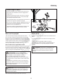
NOTE: In these instructions, “left” and “right” are referenced from the operating
position.
3
Not for
Reproduction

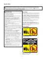
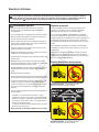
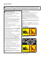
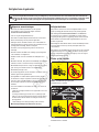
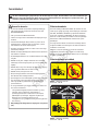
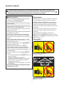
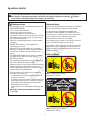
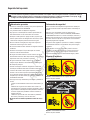
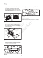
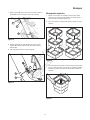
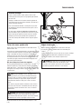
Safety Decals
Several safety labels are installed on the unit to remind you
of important information while you are operating your unit.
All DANGER, WARNING, CAUTION and instructional mes-
sages on your rider, attachments and mower should be
carefully read and obeyed. Personal bodily injury can result
when these instructions are not followed. The safety decals
below are on your product.
If any decals are lost or damaged, replace them at once.
See your local dealer for replacements.
These labels are easily applied and will act as a con-
stant visual reminder to you, and others who may use the
equipment, to follow the safety instructions necessary for
safe, effective operation.
Attachment Decal
Decal - CAUTION Grass Catcher
Part Number 7103194
Decal - CAUTION Instruction
Part Number 7103195
4
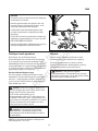
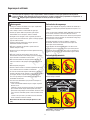
Read these safety rules and follow them closely. Failure to obey these rules could result in loss of control of unit,
severe personal injury or death to you, or bystanders, or damage to property or equipment. The triangle in text
signifi es important cautions or warnings which must be followed.
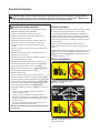
Operator Safety
General Warnings
• Know the unit’s controls and how to stop quickly. READ
THE OPERATOR’S MANUALS.
• Read and obey all safety decals.
• Only allow responsible adults, who are familiar with the
instructions, to operate the unit.
• Disengage the PTO. Shut off the engine and wait for
all moving parts to stop before attaching, adjusting, or
disconnecting any part of the collection system.
• Check the collection system to make sure it is securely
installed to the unit.
• DO NOT operate the unit without either the entire grass
catcher or the deflector in place.
• Turn off the PTO to disengage the blades when not
mowing.
• DO NOT mow in reverse unless absolutely necessary.
Always look down and behind before and while travelling
in reverse.
• DO NOT turn sharply when travelling alongside a building
or any object. Slow down before turning.
• DO NOT carry passengers.
• When collection system is removed from the mower
deck, the deflector must be properly installed.
• Collector bags are subject to deterioration and wear
during normal use. Inspect the bag periodically for tears,
holes, or weak spots and replace with a new bag that
meets manufacturer’s durability standards.
• For added stability and to prevent tipping or loss of
control:
a. Use reduced speed on uneven ground and when
turning corners.
b. Reduce loads on hillsides. It is recommended that the
collection system be kept only half full when negotiating
any slopes. Start mowing on slopes when the collection
system is empty.
c. Mow up and down the face of slopes; never across
the face of any slope.
• Never operate on slopes greater than 17.6% (10°).
Not for
Reproduction

Fastener Identifi cation
6x93 (5)
26x239 (1)
15x66 (6)
18x15 (5)
15x32 (5)
2x39 (1)
2x64 (2) 4x71 (1)
4x24 (5)
4x21 (2)
15x89 (5)
15x81 (2)
193x1 (8)
1x125 (1)
15x41 (1)
15x108 (2) 10851 Z (2)
1x141 (2)
17x38 (3)
1x10⁶ (3)
5
Not for
Reproduction

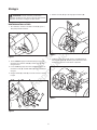
Assembly
6
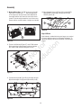
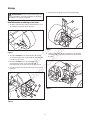
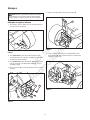
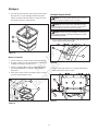
Figure 1
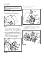
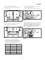
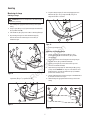
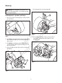
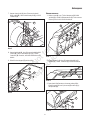
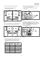
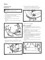
WARNING: Before beginning any service work turn
off the PTO, set the parking brake, turn off the ignition,
and disconnect the spark plug wire(s).
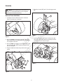
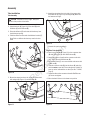
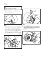
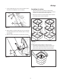
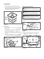
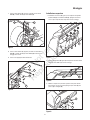
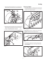
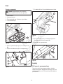
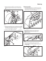
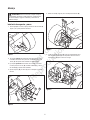
Hitch and Frame Installation
1. If equipped, remove and discard the two screws (A,
Figure 1) from the rear of the frame.
A
2. Attach the bottom of the bagger mount (A, Figure 2) to
tractor frame with the 1x125 bolt (B) and 15x41 nut (C).
Do not tighten at this time.
3. Attach the back of the bagger mount to tractor frame with
two 1x141 bolts (D), 10851Z washers (E), and 15x108
nuts (F) and tighten.
4. Tighten bolt (B) and nut (C) using ratchet wrench and
socket.
Figure 2
A
B
C
D
F
E
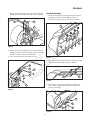
5. Mount the channel (A, Figure 3) into the bagger mount
(B).
Figure 3
A
B
6. Install the channel pin (A, Figure 4) fully into the right
side of the channel (B). Rotate the channel pin counter-
clockwise to lock the channel in place.
Figure 4
B
A
A
B
Not for
Reproduction

Assembly
7
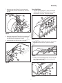
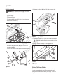
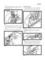
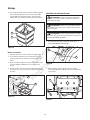
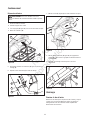
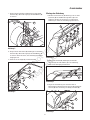
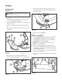
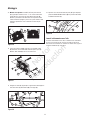
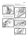
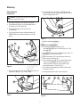
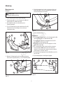
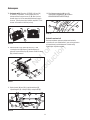
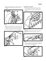
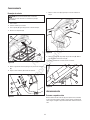
Cover Installation
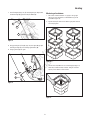
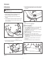
1. Assemble the hinge (A, Figure 7) to the cover with four
4x24 bolts (B) and 15x66 locknuts (C). Push the hinge
toward the top of the cover. Tighten the fasteners.
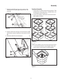
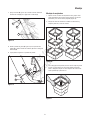
7. Mount the outer tube (A, Figure 5) to the channel with
three 6x93 bolts (B), 18x15 lockwashers (C), and 15x32
nuts (D).
Figure 5
BA
C
8. Mount the center tube (A, Figure 6) to the channel with
two 6x93 bolts (B), 18x15 lockwashers (C), and 15x32
nuts (D). Make sure the fasteners are tight.
9. Attach the three caps (E) to the ends of the tubes. Figure 7
B
A
Figure 6
A
B
D
C
E
C
2. Attach the handle (A, Figure 8) to the cover with two 4x21
bolts (B) and 15x81 nuts (C). Tighten the fasteners.
Figure 8
C
AB
3. Set the cover in the operating position on top of the outer
tube. Fasten the hinge (A, Figure 9) to the channel (B)
with pin (C) and hair pin (D).
Figure 9
B
A
D
C
D
Not for
Reproduction

Assembly
8
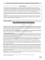
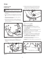
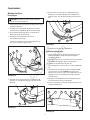
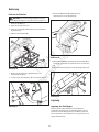
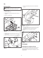
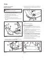
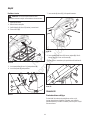
Tube Installation
Tube Assembly
CAUTION: The blade has sharp edges. Always be
careful of the position of the blade.
1. Move the deck lift lever to the highest cut position.
2. Attach latch pin (A, Figure 10) to the chute (B) with
2x39 bolt (C) and 15x89 nut (D).
3. Raise the defl ector (E) and rotate the blade away from
the discharge opening.
4. Slide the extension tube under the defl ector bracket (F).
Note: Bolts on defl ector bracket may need to be loos-
ened.
Figure 10
A
C
B
D
E
5. Mount the extension tube to the top of the mower deck
with wingnut (A, Figure 11) and 2x64 bolt (B).
Figure 11
B
A
Figure 12
A B
6. Attach the extension tube to the side of the mower deck
with 2x64 bolt (A, Figure 12) and wingnut (B).Make sure
the fasteners are tight.
Connector Tube Assembly
1. Attach top of handle (A, Figure 13) to the connector tube
(B) with 4x24 screw (C) and 15x66 locknut (D).
2. Attach the bottom of handle to the connector tube with
4x71 screw (E) and 15x66 locknut (D).
3. Place rubber latch (F) over screw threads and secure with
15x89 nut (G).
4. Slide the connector tube (B) into the elbow (H) and align
with the center screw hole. Ensure the bottom of elbow is
insert up to the indicated line on decal (Part No. 7103195,
Page 4).
5. Fasten the elbow to the connector tube with 26x239 screw
(I). Do not over tighten.
6. Move the deck lift lever to the lowest cut position.
Figure 13
F
E
B
C
A D GIH
F
7. Connect the spark plug wire(s).
Not for
Reproduction

Assembly
9
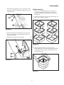
7. Hold the handle (A, Figure 14) on the connector tube.
Slide the end of the elbow (B) through the hole in the
cover (C).
Figure 14
A
C
B
8. Align the rubber latch (A, Figure 15) with the latch pin (B)
and slide the connector tube (C) over the extension chute
(D).
9. Secure the rubber latch to the latch pin.
Figure 15
B
D
A
C
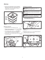
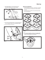
Figure 16
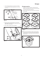
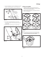
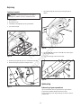
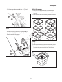
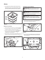
3. For each container group, lift the large top section (Figure
17) until all three sections connect together. Make sure
all four corners of each section are locked together.
Figure 17
Container Assembly
1. Separate the six container sections into two groups. Each
group will have a large top section, a middle section, and
a small bottom section (Figure 16).
2. Look for the numbers on the side of each section and fi t
them together as shown.
Not for
Reproduction

10
Assembly
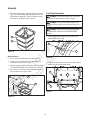
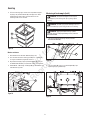
4. For each container group, fasten the large top section (A,
Figure 18) and the middle section (B) together with four
193x1 plastic fasteners (C). Push the fasteners through
the holes from the inside of each container.
Figure 18
C
B
A
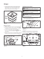
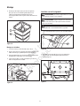
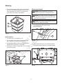
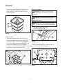
Mount Containers
1. Tilt the seat forward. Raise the cover (A, Figure 19).
2. If desired, place optional plastic collection bags in the
containers for easy removal of grass.
3. Slide the containers (B) onto the support tubes (C). Make
sure the CAUTION label, on the containers, is to the rear.
4. Lower the cover. Pull back on the handle (D) and push
the cover down until it locks in place.
Figure 19
B
A
D
C
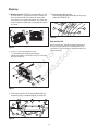
Figure 21
C
A
B
2. Remove hair pin (A, Figure 21) and spacer (B). Remove
hanger rod (C) and disconnect hanger.
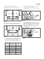
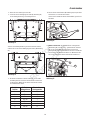
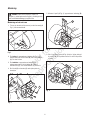
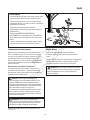
Front Weight Installation
WARNING: Use the front weights when you operate
on a slope or where the lawn is rough or uneven.
WARNING: Do not ride up or down slopes that are
too steep to back straight up. Never ride the unit across a
slope.
WARNING: The deck lift lever is spring loaded. Make
sure the lift lever is locked in the LEVEL ADJUSTMENT
position.
1. Move the deck lift lever (A, Figure 20) to the LEVEL
ADJUSTMENT position (B).
Figure 20
B
A
Not for
Reproduction

11
Assembly
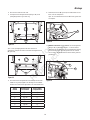
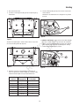
3. Turn the steering wheel completely to the left.
4. Remove the three mounting screws (A, Figure 22) from
hanger bracket and discard.
Figure 22
A
Note: If the hanger bracket is installed with two screws, only
remove the upper mounting screws (A, Figure 23).
Figure 23
A
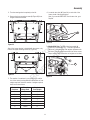
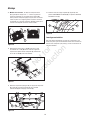
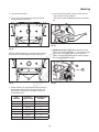
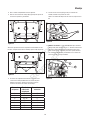
6. Locate the two slots (A, Figure 24) on each side of the
frame, ahead of the engine pulleys.
Note: If your model DOES NOT have the two slots, go to
Step 8b.
Figure 24
A
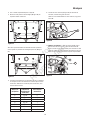
7a. Models With Slots: The TOP of the front weight (A,
Figure 25) is marked with a “T”. From the right side of
the tractor, slide one of the front weights up between the
two slots. Push the weight toward the front of the mower.
Repeat until the required number of weights are installed.
Figure 25
B
A
5. The number of containers in your grass bagger and the
size of the mower housing determine the number of front
weights required. Select the number of weights required,
based on the chart below.
Number of
Containers Size of
Mower Deck Required
Front Weights
2 97cm 5
2 103cm 5
2 107cm 5
3 107cm 7
3 117cm 6
3 112cm 6
3 132cm 6
Not for
Reproduction

12
Assembly
Figure 26
A
T
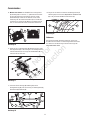
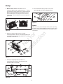
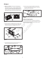
7b. Models Without Slots: The TOP of the front weight (A,
Figure 26) is marked with a “T”. Slide the large notch
of the weight over the right frame channel (B). Rotate
the weight until the other notch fi ts over the left frame
channel. Push the weight toward the front of the mower.
Repeat until the required number of weights are installed.
Figure 28
A
E
B
C
D
Figure 27
C
D
9. Connect the hanger (A, Figure 28) to the hanger bracket
(B) with the hanger rod (C) spacer (D) and hair pin (E).
8. Fit three 1x10⁶ bolts (A, Figure 27) with 17x38 washers
(B) through holes in deck hanger bracket and weights
(C). Install 15x89 nuts (D) and tighten securely.
Figure 29
B
A
10. Move the deck lift lever (A, Figure 29) from the LEVEL
ADJUSTMENT position (B) to the desired CUTTING
HEIGHT position (C).
C
High Lift Blade
High lift blades, included with the grass bagger, are required
to properly discharge grass into the bagger attachment. To
replace the blade(s), follow the instructions in the Operator’s
manual.
B
B
A
Not for
Reproduction

Operation
13
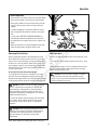
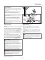
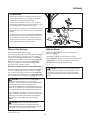
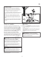
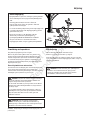
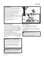
Before Operation
Clear the lawn of all sticks, stones, wire and other debris
which may be caught or thrown by the mower blades.
Check grass condition. If wet, wait until later in the day.
If grass is wet, the grass catcher is likely to become
plugged.
For effi cient bagging, air circulation under the mower
deck, through the chute and into the bag is very impor-
tant.
For this reason, BEFORE YOU BEGIN MOWING you
should make certain the underside of the mower and
the underside of the catcher lid are free from grass and
debris.
Make sure that there is a snug fi t between mower deck,
blower housing, tubes, and grass catcher cover.
Mowing with the Catcher
Always operate with throttle at full speed when mowing.
Grass should be cut often, and not too short. If grass is too
long or lush it may be necessary to keep ground speed to a
minimum or to cut only half the width of the mower to pre-
vent clogging. If grass is long, operate with mower in high
cutting position for fi rst pass, cutting again in a lower posi-
tion on a second pass.
Do not open the cover with mower engaged.
If a large amount of cut grass is spilling out from under
deck, the tube may be plugged or the bags may be full—
discontinue mowing, stop the unit, disengage the PTO, shut
off the engine and then empty the catcher or clear the tube.
After Operation
Remove any debris from the screen on the underside of the
lid.
The blower housing and tube should be removed for clean-
ing.
Inspect the grass bags for wear or damage. Make sure that
there is a snug fi t between mower deck, blower housing,
tubes, and grass catcher cover.
WARNING: ALWAYS shut off the tractor. Disengage
the PTO, and allow all moving parts to stop BEFORE
disconnecting or clearing tube, or emptying catcher.
Before leaving the operator’s position for any reason,
engage the parking brake, disengage the PTO, stop the
engine and remove the key.
To reduce fi re hazard, keep the engine, rider and mower
free of grass, leaves and excess grease. Do not stop
or park rider over dry leaves, grass or combustible
materials.
CAUTION: Before you begin operating the unit be
certain you have read all of the safety and operational
information of this instruction sheet, as well as the
Operator’s Manual for the tractor and any other
attachments.
NOTE: Never operate on slopes greater than 17.6% (10°).
CAUTION: Do not leave grass in bagger containers.
Empty containers after each use and before storing.
Failure to do so may result in spontaneous combustion
which could develop into a fi re.
Not for
Reproduction

14
Collector Removal
WARNING: For operation without bagger, the mower
defl ector must be installed in the down position.
1. Stop the engine.
2. Tilt the seat forward.
3. Pull the handle (A, Figure 30) back and raise the cover.
4. Remove the containers (B).
Figure 30
A
B
8. Disconnect the rubber latch (A, Figure 31) from the
extension tube (B).
9. Separate the connector tube (C) from the extension tube.
Figure 31
A
B
C
10. Remove the elbow (A, Figure 32) and connector tube
from the cover.
A
Figure 32
11. Remove the hair pin (A, Figure 33) from the channel pin
(B). Rotate the channel pin and remove from the channel
(C).
12. Lift the channel assembly off the bagger mount.
Figure 33
B
A
C
Operation
Storing The Grass Catcher
Remove all loose debris from grass catcher parts, includ-
ing the screen under the cover. Clean parts using a mild
detergent and water. Rinse and dry thoroughly. Store in a
dry area.
Storage
Not for
Reproduction

7103204 -C
Rev. C
Briggs & Stratton Yard Power Products Group
Copyright © 2010 Briggs & Stratton Corporation
Milwaukee, WI USA. All Rights Reserved
Not for
Reproduction

BRIGGS & STRATTON POWER PRODUCTS GROUP, L.L.C. GARANTIE DU PROPRIÉTAIRE POLITIQUE
GARANTIE LIMITÉE
Si une pièce de cet équipement présente un vice de matériau ou de fabrication, Briggs & Stratton Power Products Group,
LLC la réparera ou la remplacera gratuitement. Si une pièce du moteur Briggs and Stratton (si équipé) présente un vice de
matériau ou de fabrication, Briggs & Stratton Corporation la réparera ou la remplacera gratuitement. Les frais de transport du
produit à réparer ou remplacer seront, dans le cadre de cette garantie, réglés par l’acheteur. Cette garantie est en vigueur pour
les périodes de temps et conformément aux conditions stipulées ci-dessous. Pour obtenir le service de garantie, veuillez vous
adresser au distributeur autorisé le plus proche dont vous trouverez les coordonnées sur www.BriggsandStratton.com.
Il n’existe aucune autre garantie expresse. Les garanties implicites, y compris celles de qualité marchande et d’adaptation à
un emploi particulier, sont limitées à une année à partir de la date d’acquisition ou conformément à ce qui est prévu par la loi.
La responsabilité juridique pour les dommages consécutifs ou indirects est excluse dans la mesure où l’exclusion est autorisée
par la loi.
Certains États ou pays ne permettent pas les limitations de durée de la garantie implicite. Certains États ou pays n’autorisent
pas l’exclusion ou la limitation des dommages consécutifs ou indirects. Dans ce cas, la limitation ci-dessus ne s’applique pas
à votre cas. La présente garantie vous offre des droits juridiques spécifiques et il se peut que vous ayez d’autres droits qui
varient d’une juridiction à une autre, ou de pays à pays.
PÉRIODE DE GARANTIE
La garantie commence à la date d’acquisition du produit par le consommateur au détail ou commercial final, et continue tout au
long de la période indiquée ci-dessus. « Utilisation par le consommateur » signifie que le produit sera utilisé par un consommateur
au détail dans un but privé. « Utilisation commerciale » indique toutes les autres utilisations possibles, y compris commerciales,
génératrices de revenus ou locatives. Une fois que le produit a été utilisé dans un but commercial, il sera considéré comme d’utili-
sation commerciale dans le cadre de cette garantie.
Aucun enregistrement de la garantie n’est nécessaire pour obtenir la garantie des produits de marque Briggs & Stratton. Veuillez
garder le reçu de votre achat. Si vous ne pouvez pas fournir la preuve de l’achat au moment de faire une demande se rapportant à
la garantie, la date de fabrication du produit sera utilisée pour déterminer l’admissibilité à la garantie.
À PROPOS DE VOTRE GARANTIE
Nous sommes totalement disponibles à réaliser des réparations dans le cadre de la garantie et nous nous prions d’accepter no
excuses anticipées pour les désagréments éventuels. Le service de garantie est offert uniquement par l’intermédiaire des distribu-
teurs autorisés par Briggs & Stratton ou BSPPG, LLC.
Parfois les demandes de réparations dans le cadre de la garantie peuvent ne pas être pertinentes. Cette garantie couvre unique-
ment les vices de matériau ou de fabrication. Elle ne couvre pas des dommages causés par une mauvaise utilisation ou des abus,
un mauvais entretien ou une réparation incorrecte, une usure normale ou l’utilisation de carburant vicié ou non approuvé.
Mauvaise utilisation et abus - Une bonne utilisation, telle que prévue, du produit est décrite dans le manuel de l’opérateur.
L’utilisation de la machine de façon autre que celle décrite dans le manuel de l’opérateur ou son utilisation après qu’elle ait été
endommagée annulera la garantie. Vous ne pourrez vous prévaloir de la garantie si le numéro de série sur la machine a été sup-
primé ou si la machine a été modifiée d’une manière quelconque, ou si elle présente des preuves d’abus, tel que coups, corrosion
par l’eau ou des produits chimiques.
Mauvais entretien ou réparation - Cette machine doit être entretenue conformément aux procédures et aux intervalles indiqués
dans le manuel de l’opérateur, l’entretien et les réparations doivent être effectués avec des pièces d’origine Briggs & Stratton. Les
dommages causés par un manque d’entretien ou l’utilisation de pièces n’étant pas d’origine ne sont pas couverts par la garantie.
Usure normale - Comme tous les appareils mécaniques, malgré un bon entretien, le vôtre est sujet à une usure. La présente
garantie ne couvre pas les réparations lorsque la durée de vie de la machine s’est achevée après une utilisation normale. Les arti-
cles d’entretien et d’usure, tels que filtres, courroies, lames et plaquettes de freins (les plaquettes de frein moteur sont couvertes)
ne sont pas couverts par la garantie, uniquement en raison de leur caractéristique d’usure, à moins que la cause soit due à des
vices du matériel ou de fabrication.
Carburant vicié - Afin de fonctionner correctement, cette machine doit être alimentée avec un carburant propre conforme au cri-
tère précisé dans le manuel de l’opérateur. Les dommages causés par un carburant vicié (fuites de carburant, conduites bouchées,
soupapes collantes, etc.) ne sont pas couverts par la garantie.
* Concerne les moteurs Briggs and Stratton seulement. La couverture pour les moteurs autres que Briggs and Stratton
est offerte par le fabricant du moteur.
Article Utilisation par le consommateur Utilisation commerciale :
Équipement 1 an -
fr
Not for
Reproduction

Table des matières
Sécurité de l’opérateur .................................................................... 4
Avertissements généraux .................................................................................. 4
Étiquettes de sécurité ........................................................................................ 4
Étiquette autocollante des accessoires .............................................................. 4
Identification des pièces de fixation .................................................................. 5
Montage. ..................................................................................... 6
Installation de l’attelage et du châssis ............................................................... 6
Installation du capot .......................................................................................... 7
Installation du tube ........................................................................................... 8
Assemblage du container .................................................................................. 9
Installation du contrepoids avant ...................................................................... 10
Lame hypersustentatrice ................................................................................... 12
Fonctionnement............................................................................. 13
Dépose du collecteur ........................................................................................ 14
Remisage..................................................................................... 14
REMARQUE : Dans les instructions qui suivent, « gauche » et « droite » font référence à
la position de l’utilisateur.
Not for
Reproduction

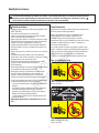
Étiquettes de sécurité
Plusieurs étiquettes portant des consignes de sécurité sont
installées sur la machine pour vous rappeler d’importantes
informations pendant que vous utilisez votre machine.
Tous les messages DANGER, AVERTISSEMENT, ATTENTION
ainsi que les instructions sur votre tracteur, les accessoires et la
tondeuse doivent être lus attentivement et respectés. Des blessures
corporelles peuvent résulter du non-respect de ces instructions.
Les étiquettes autocollantes de sécurité ci-dessous sont sur votre
produit.
Si des étiquettes autocollantes sont perdues ou endommagées,
les remplacer aussitôt. Consulter votre revendeur local pour leur
remplacement.
Ces étiquettes s’appliquent facilement et serviront de constant
rappel visuel pour l’utilisateur, et toute autre personne utilisant
l’équipement, de respecter les instructions de sécurité nécessaires
pour un fonctionnement sûr et effi cace.
Étiquette autocollante des accessoires
Étiquette autocollante - ATTENTION Sac à herbe
Numéro de référence de la pièce 7103194
Étiquette autocollante - ATTENTION Instructions
Numéro de référence de la pièce 7103195
4
Lire ces règles de sécurité et les suivre de près. Ne pas observer ces consignes pourrait entraîner une perte de contrôle de
l’unité, des blessures corporelles graves, voir la mort, pour l’utilisateur ou les spectateurs, ou endommager le matériel ou
l’équipement. Le triangle situé dans le texte indique un danger ou une mise en garde qui doit être respecté.
Sécurité de l’utilisateur
Avertissements généraux
• Prendre connaissance des commandes de la machine et
de la façon de l’arrêter rapidement. LIRE LES MANUELS
D’UTILISATION.
• Lire et respecter toutes les étiquettes autocollantes de sécurité.
• Autoriser seulement des adultes responsables et familiarisés
avec les instructions à utiliser la machine.
• Débrayer la PDF. Éteindre le moteur et attendez que toutes les
pièces mobiles s’arrêtent avant de fixer, régler ou déconnecter
toute pièce du système de ramassage.
• Vérifier le système de ramassage pour vous assurer qu’il est
solidement installé sur la machine.
• NE PAS faire fonctionner la machine sans que le sac à herbe ou
le déflecteur ne soit totalement en place.
• Couper la PDF pour débrayer les lames quand la tondeuse n’est
pas en marche.
• NE PAS tondre en marche arrière à moins que cela ne soit
absolument indispensable. Toujours regarder vers le bas et vers
l’arrière avant et pendant une marche arrière.
• NE PAS PRENDRE de virages brusques en passant le long d’un
bâtiment ou de tout autre objet. Ralentir avant de prendre un
virage.
• NE PAS transporter de passagers.
• Quand le système de ramassage est retiré du plateau de coupe
de la tondeuse, le déflecteur doit être convenablement installé.
• Les sacs du collecteur sont destinés à se détériorer et à s’user
pendant une utilisation normale. Vérifier périodiquement le
sac pour les déchirures, trous ou points faibles et le remplacer
par un nouveau sac satisfaisant les normes de durabilité du
fabricant.
• Pour davantage de stabilité et pour éviter tout renversement ou
perte de contrôle :
a. Ralentir sur un terrain irrégulier ou dans les virages.
b. Réduire les charges sur les pentes. Il est recommandé de
conserver le système de ramassage à moitié plein seulement
sur les pentes. Commencer à tondre sur les pentes quand le
système de ramassage est vide.
c. Tondre en montant et en descendant les pentes ; ne jamais
tondre en travers d’une pente.
• Ne jamais utiliser sur des pentes supérieures à 17,6 % (10°).
Not for
Reproduction

Identifi cation des pièces de fi xation
6x93 (5)
26x239 (1)
15x66 (6)
18x15 (5)
15x32 (5)
2x39 (1)
2x64 (2) 4x71 (1)
4x24 (5)
4x21 (2)
15x89 (5)
15x81 (2)
193x1 (8)
1x125 (1)
15x41 (1)
15x108 (2) 10851 Z (2)
1x141 (2)
17x38 (3)
1x10⁶ (3)
5
Not for
Reproduction

Montage
6
Figure 1
AVERTISSEMENT : Avant de commencer tout entretien,
coupez la PDF, serrez le frein à main, coupez le contact et
déconnectez le(s) fi l(s) des bougies d’allumage.
Installation de l’attelage et du châssis
1. Si la machine en est équipée, retirez et jetez les deux vis (A,
Figure 1) de l’arrière du châssis.
A
2. Attachez le bas de la monture de l’ensacheuse (A, Figure 2)
au châssis du tracteur à l’aide du boulon de 1 x 125 (B) et de
l’écrou de 15 x 41 (C). Ne serrez pas pour l’instant.
3. Attachez l’arrière de la monture de l’ensacheuse au châssis du
tracteur à l’aide de deux boulons de 1 x 141 (D), des rondelles
10851Z (E) et des écrous de 15 x 108 (F) et serrez.
4. Serrez le boulon (B) et l’écrou (C) en utilisant une clé a cliquet
et une douille.
Figure 2
A
B
C
D
F
E
5. Installez le montant (A, Figure 3) dans la monture de
l’ensacheuse (B).
Figure 3
A
B
6. Faites rentrer complètement la goupille du montant (A, Figure 4)
dans le côté droit du montant (B). Faites pivoter la goupille du
montant dans le sens contraire des aiguilles d’une montre pour
mettre en place le montant et le verrouiller.
Figure 4
B
A
A
B
Not for
Reproduction
Sidan laddas...
Sidan laddas...
Sidan laddas...
Sidan laddas...
Sidan laddas...
Sidan laddas...
Sidan laddas...
Sidan laddas...
Sidan laddas...
Sidan laddas...
Sidan laddas...
Sidan laddas...
Sidan laddas...
Sidan laddas...
Sidan laddas...
Sidan laddas...
Sidan laddas...
Sidan laddas...
Sidan laddas...
Sidan laddas...
Sidan laddas...
Sidan laddas...
Sidan laddas...
Sidan laddas...
Sidan laddas...
Sidan laddas...
Sidan laddas...
Sidan laddas...
Sidan laddas...
Sidan laddas...
Sidan laddas...
Sidan laddas...
Sidan laddas...
Sidan laddas...
Sidan laddas...
Sidan laddas...
Sidan laddas...
Sidan laddas...
Sidan laddas...
Sidan laddas...
Sidan laddas...
Sidan laddas...
Sidan laddas...
Sidan laddas...
Sidan laddas...
Sidan laddas...
Sidan laddas...
Sidan laddas...
Sidan laddas...
Sidan laddas...
Sidan laddas...
Sidan laddas...
Sidan laddas...
Sidan laddas...
Sidan laddas...
Sidan laddas...
Sidan laddas...
Sidan laddas...
Sidan laddas...
Sidan laddas...
Sidan laddas...
Sidan laddas...
Sidan laddas...
Sidan laddas...
Sidan laddas...
Sidan laddas...
Sidan laddas...
Sidan laddas...
Sidan laddas...
Sidan laddas...
Sidan laddas...
Sidan laddas...
Sidan laddas...
Sidan laddas...
Sidan laddas...
Sidan laddas...
Sidan laddas...
Sidan laddas...
Sidan laddas...
Sidan laddas...
Sidan laddas...
Sidan laddas...
Sidan laddas...
Sidan laddas...
Sidan laddas...
Sidan laddas...
Sidan laddas...
Sidan laddas...
Sidan laddas...
Sidan laddas...
Sidan laddas...
Sidan laddas...
Sidan laddas...
Sidan laddas...
Sidan laddas...
Sidan laddas...
Sidan laddas...
Sidan laddas...
Sidan laddas...
Sidan laddas...
Sidan laddas...
Sidan laddas...
Sidan laddas...
Sidan laddas...
Sidan laddas...
Sidan laddas...
Sidan laddas...
Sidan laddas...
Sidan laddas...
Sidan laddas...
Sidan laddas...
Sidan laddas...
Sidan laddas...
Sidan laddas...
Sidan laddas...
Sidan laddas...
Sidan laddas...
Sidan laddas...
Sidan laddas...
Sidan laddas...
Sidan laddas...
Sidan laddas...
Sidan laddas...
Sidan laddas...
Sidan laddas...
Sidan laddas...
Sidan laddas...
Sidan laddas...
Sidan laddas...
Sidan laddas...
Sidan laddas...
Sidan laddas...
Sidan laddas...
Sidan laddas...
Sidan laddas...
Sidan laddas...
-
 1
1
-
 2
2
-
 3
3
-
 4
4
-
 5
5
-
 6
6
-
 7
7
-
 8
8
-
 9
9
-
 10
10
-
 11
11
-
 12
12
-
 13
13
-
 14
14
-
 15
15
-
 16
16
-
 17
17
-
 18
18
-
 19
19
-
 20
20
-
 21
21
-
 22
22
-
 23
23
-
 24
24
-
 25
25
-
 26
26
-
 27
27
-
 28
28
-
 29
29
-
 30
30
-
 31
31
-
 32
32
-
 33
33
-
 34
34
-
 35
35
-
 36
36
-
 37
37
-
 38
38
-
 39
39
-
 40
40
-
 41
41
-
 42
42
-
 43
43
-
 44
44
-
 45
45
-
 46
46
-
 47
47
-
 48
48
-
 49
49
-
 50
50
-
 51
51
-
 52
52
-
 53
53
-
 54
54
-
 55
55
-
 56
56
-
 57
57
-
 58
58
-
 59
59
-
 60
60
-
 61
61
-
 62
62
-
 63
63
-
 64
64
-
 65
65
-
 66
66
-
 67
67
-
 68
68
-
 69
69
-
 70
70
-
 71
71
-
 72
72
-
 73
73
-
 74
74
-
 75
75
-
 76
76
-
 77
77
-
 78
78
-
 79
79
-
 80
80
-
 81
81
-
 82
82
-
 83
83
-
 84
84
-
 85
85
-
 86
86
-
 87
87
-
 88
88
-
 89
89
-
 90
90
-
 91
91
-
 92
92
-
 93
93
-
 94
94
-
 95
95
-
 96
96
-
 97
97
-
 98
98
-
 99
99
-
 100
100
-
 101
101
-
 102
102
-
 103
103
-
 104
104
-
 105
105
-
 106
106
-
 107
107
-
 108
108
-
 109
109
-
 110
110
-
 111
111
-
 112
112
-
 113
113
-
 114
114
-
 115
115
-
 116
116
-
 117
117
-
 118
118
-
 119
119
-
 120
120
-
 121
121
-
 122
122
-
 123
123
-
 124
124
-
 125
125
-
 126
126
-
 127
127
-
 128
128
-
 129
129
-
 130
130
-
 131
131
-
 132
132
-
 133
133
-
 134
134
-
 135
135
-
 136
136
-
 137
137
-
 138
138
-
 139
139
-
 140
140
-
 141
141
-
 142
142
-
 143
143
-
 144
144
-
 145
145
-
 146
146
-
 147
147
-
 148
148
-
 149
149
-
 150
150
-
 151
151
-
 152
152
-
 153
153
-
 154
154
-
 155
155
-
 156
156


Simplicity 7600082 OPERATORS MANUAL FOR TWIN BAGGER ATTACHMENT / 38", 40", 42" MOWER Användarmanual
- Kategori
- Gräsklippare
- Typ
- Användarmanual
på andra språk
- italiano: Simplicity 7600082 OPERATORS MANUAL FOR TWIN BAGGER ATTACHMENT / 38", 40", 42" MOWER Manuale utente
- eesti: Simplicity 7600082 OPERATORS MANUAL FOR TWIN BAGGER ATTACHMENT / 38", 40", 42" MOWER Kasutusjuhend
- español: Simplicity 7600082 OPERATORS MANUAL FOR TWIN BAGGER ATTACHMENT / 38", 40", 42" MOWER Manual de usuario
- Deutsch: Simplicity 7600082 OPERATORS MANUAL FOR TWIN BAGGER ATTACHMENT / 38", 40", 42" MOWER Benutzerhandbuch
- português: Simplicity 7600082 OPERATORS MANUAL FOR TWIN BAGGER ATTACHMENT / 38", 40", 42" MOWER Manual do usuário
- français: Simplicity 7600082 OPERATORS MANUAL FOR TWIN BAGGER ATTACHMENT / 38", 40", 42" MOWER Manuel utilisateur
- dansk: Simplicity 7600082 OPERATORS MANUAL FOR TWIN BAGGER ATTACHMENT / 38", 40", 42" MOWER Brugermanual
- Nederlands: Simplicity 7600082 OPERATORS MANUAL FOR TWIN BAGGER ATTACHMENT / 38", 40", 42" MOWER Handleiding