ABB PositionMaster EDP300 Bruksanvisningar
- Typ
- Bruksanvisningar

—
ABB MEASUREMENT & ANALYTICS | INSTRUCTION
PositionMaster EDP300
Instruction – PositionMaster EDP300
For digital positioners EDP300 – Page 2
Anleitung – PositionMaster EDP300
Für digitale Stellungsregler EDP300 – Seite 4
Instruktion – PositionMaster EDP300
För digital lägesomkopplare EDP300 – Sida 6

2 – XS PositionMaster EDP300 DIGITAL POSITIONER | IN/EDP300/PRESSURE_OPTION-XS REV. A
Information on the modification and installation of the pressure option in the EDP300
1 Installing the pressure option
CAUTION
Risk of injury
Risk of injuries due to flying components as well as significant noise emissions.
• Prior to disassembly, all connected compressed air lines must be depressurized.
Change from two to one column
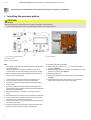
1 I/P converter pneumatic system
2 Position sensor
3 Pressure option
Figure 1: Printed circuit board
Change from one to tw o columns
Note
• The supply voltage must be switched off before the pressure
option is installed.
• The bonding wires for the pressure option must not be
touched. Doing so will cause damage to the option module.
• Before using the device, a high-voltage test in accordance
with IEC must be performed.
1. Loosen the screws for the housing cover and remove it.
2. Loosen all cable connections on the screw terminals.
3. If present, unscrew the option modules and remove them
from the side.
4. If present, remove the mechanical position indication and
screw off the shaft extension (as well as the mechanical alarm
signaling unit if applicable).
5. Remove the screws for the plastic cover and remove the
cover.
6. Remove both plug connectors from the printed circuit board.
7. Unscrew the fixing screws for the printed circuit board and
carefully remove the printed circuit board.
8. Unscrew the screws on the upper side of the pneumatics and
remove the cover plate.
9. Carefully attach the pressure option to the pneumatics and
screw it in place so that the screws are hand-tight.
10.Install the printed circuit board.
11. Attach both plug connectors
1, 2 to the printed circuit
board (see Figure 1).
12. Attach the plug connectors for the pressure option
3 to the
printed circuit board (see Figure 1).
13. Attach the plastic cap.
14. If necessary, install option modules and set the mechanical
feedback.
15. Attach the housing cover and screw it on to the housing.
Tighten the screws so that they are hand-tight.
2

PositionMaster EDP300 DIGITAL POSITIONER | IN/EDP300/PRESSURE_OPTION-XS REV. A XS – 3
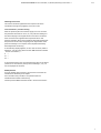
Mounting instructions
The screws should be tightened in the sequence as shown
numbered in the figure by applying a torque of 1 Nm.
Test instructions / function testing
After the pressure plate is mounted, supply from 4 to 20 mA to
the positioner and look for the P / P1 / P2 pressure readings on
the device display in the ‘Signals Views’ menu item. The device
does not need to be supplied with compressed air for this
purpose. Basically, all 3 pressure readings should be displayed at
this point and in this case, everything is OK. Adjustment of the
pressure readings is not required, since the plate has already
been adjusted at the factory.
If the following display appears, an error has occurred. (‘Plate is
defective’ In this case, please contact ABB Automation GmbH
- Service Instruments -):
P ---
P1 ---
P2 ---
If the pressure plate is not connected with the main circuit board
(connector is not inserted), the 3 pressure readings P / P1 / P2
are not displayed in the menu.
EX Requirement
If we are dealing with Ex devices, the customer must have the
modification checked by an Ex expert.
If this should not be possible, it is imperative that the
modification be tested at the factory!
Contact partner: ABB Automation GmbH - Service Instruments -
3

4 – XS PositionMaster EDP300 DIGITAL POSITIONER | IN/EDP300/PRESSURE_OPTION-XS REV. A
Change from one to tw o columns
Change from two to one column
Information zum Umbau und Einbau der Druckoption beim EDP300
2 Einbau der Druckoption
VORSICHT
Verletzungsgefahr
Verletzungsgefahr durch umherfliegende Bauteile sowie starke Geräuschemission.
• Vor der Demontage müssen sämtliche angeschlossenen Druckluftleitungen drucklos sein.
Change from two to one column
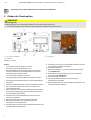
1 I/P-Umformer Pneumatik
2 Wegsensor
3 Druckoption
Abbildung 2: Leiterplatte
Change from one to tw o columns
Hinweis
• Vor dem Einbau der Druckoption muss die
Versorgungsspannung abgeschaltet sein.
• Die Bondingdrähte der Druckoption dürfen nicht berührt
werden. Die Berührung der Bondingdrähte führt zu einer
Beschädigung des Optionsmoduls.
• Vor dem Einsatz des Gerätes muss eine
Hochspannungsprüfung gemäß IEC durchgeführt werden.
1. Schrauben am Gehäusedeckel lösen und den Gehäusedeckel
abnehmen.
2. Sämtliche Kabelverbindungen an den Schraubklemmen lösen.
3. Falls vorhanden, die Optionsmodule losschrauben und
seitlich herausnehmen.
4. Falls vorhanden, die mechanische Stellungsanzeige abziehen
und die Achsverlängerung (ggf. auch die der mechanischen
Grenzwertgeber) abschrauben.
5. Schrauben der Kunststoffabdeckung entfernen und die
Abdeckung abnehmen.
6. Beide Steckverbinder von der Leiterplatte abziehen.
7. Befestigungsschrauben der Leiterplatte lösen und
Leiterplatte vorsichtig abnehmen.
8. Schrauben auf der Oberseite der Pneumatik abschrauben und
die Abdeckplatte herausnehmen.
9. Druckoption vorsichtig auf die Pneumatik aufsetzen und mit
den Schrauben handfest anschrauben.
10.Leiterplatte montieren.
11. Beide Steckverbinder (1, 2) auf die Leiterplatte aufstecken
(siehe Abbildung 2).
12. Steckverbinder der Druckoption (3) auf die Leiterplatte
aufstecken (siehe Abbildung 2).
13. Kunststoffkappe montieren.
14. Ggf. Optionsmodule montieren und mechanische
Rückmeldungen einstellen.
15. Gehäusedeckel aufsetzen und am Gehäuse anschrauben. Die
Schrauben handfest anziehen.
4

PositionMaster EDP300 DIGITAL POSITIONER | IN/EDP300/PRESSURE_OPTION-XS REV. A XS – 5
Montagehinweis
Die Schrauben sind in der Reihenfolge wie im Bild nummeriert
mit einem Anzugsmoment von 1 Nm anzuziehen.
Prüfanweisung / Funktionsüberprüfung
Nach Montage der Druckplatine den Stellungsregler mit 4 bis 20
mA versorgen und über die Geräteanzeige im Menüpunkt
„Signals View“ die Drücke P / P1 / P2 suchen. Das Gerät muss
hierfür nicht mit Druckluft versorgt werden. Es sollten an dieser
Stelle grundsätzlich alle 3 Drücke angezeigt werden, in diesem
Fall ist alles in Ordnung. Ein Abgleich der Drücke ist nicht
erforderlich, weil die Platine bereits im Werk abgeglichen wurde.
Es liegt ein Fehler vor, wenn die folgende Anzeige erscheint.
(„Platine ist defekt“ In diesem Fall bitte
ABB Automation GmbH - Service Instruments - kontaktieren):
P ---
P1 ---
P2 ---
Sollte die Druckplatine nicht mit der Hauptleiterplatte verbunden
sein (Stecker nicht aufgesteckt), so werden die 3 Drücke
P / P1 / P2 nicht im Menü angezeigt.
EX-Anforderung
Sollte es sich um Ex-Geräte handeln, muss der Kunde diesen
Umbau durch einen Ex-Sachverständigen prüfen lassen.
Sollte dies nicht möglich sein, muss der Umbau zwingend vom
Werk geprüft werden!
Ansprechpartner: ABB Automation GmbH - Service Instruments -
Change from two to one column
5

6 – XS PositionMaster EDP300 DIGITAL POSITIONER | IN/EDP300/PRESSURE_OPTION-XS REV. A
Information om ombyggnad och montering av trycktillvalet för EDP300
3 Installation av trycktillvale
OBSERVERA
Risk för personskador
Risk för personskador på grund av komponenter som slungas ut samt höga bullernivåer.
• Före demontering ska alla anslutna tryckluftsledningar vara trycklösa.
Change from two to one column
1 I/P-omformare pneumatik
2 Väggivare
3 Trycktillval
Bild 3: Ledarplatta
Change from one to tw o columns
OBS!
• Innan trycktillvalet monteras ska försörjningsspänningen
vara frånslagen.
• Trycktillvalets bondtrådar får inte vidröras. Om du kommer åt
bondtrådarna skadas tillvalsmodulen.
• Innan enheten börjar användas ska ett högspänningstest
enligt IEC genomföras.
1. Lossa skruvarna från huslocket och ta bort det.
2. Lossa samtliga kabelanslutningar från skruvplintarna.
3. Skruva loss tillvalsmodulerna i förekommande fall och ta ut
dem från sidan.
4. Dra av de mekaniska lägesindikatorerna (om sådana finns)
och skruva loss förlängningsaxeln (och i förekommande fall
den mekaniska gränsvärdesgivaren).
5. Ta bort plastskyddets skruvar och ta bort skyddet.
6. Dra loss båda kontakterna från kretskortet.
7. Lossa kretskortets fästskruvar och ta försiktigt loss
kretskortet.
8. Skruva loss skruvarna på ovansidan av pneumatiken och ta ut
täckplattan.
9. Sätt försiktigt trycktillvalet ovanpå pneumatiken och dra åt
skruvarna med handkraft.
10.Montera kretskortet.
11. Sätt i båda kontakterna (1, 2) i kretskortet (se Bild 3).
12. Sätt i kontakterna till trycktillvalet (3) i kretskortet (se Bild 3).
13. Montera plasthättan.
14. Montera eventuellt tillvalsmodulerna och ställ in mekaniska
återkopplingar.
15. Sätt på huslocket och skruva fast det på huset. Dra åt
skruvarna med handen.
6

PositionMaster EDP300 DIGITAL POSITIONER | IN/EDP300/PRESSURE_OPTION-XS REV. A XS – 7
Monteringsinstruktioner
Skruvarna ska dras åt med åtdragningsmomentet 1 Nm i den
ordningsföljd som numreringen på bilden visar.
Testinstruktioner / funktionstest
När tryckkretskortet har monterats ska du förse lägesställaren
med 4 till 20 mA och söka efter trycken P / P1 / P2 under
menyalternativet ”Signals View” på enhetens display. Du behöver
inte förse enheten med tryckluft för detta. Normalt ska alla
3 tryck visas här, i så fall är allt som det ska. Trycken behöver inte
kalibreras eftersom kretskortet redan har kalibrerats på fabriken.
Om följande indikering visas föreligger ett fel. (”Kretskortet är
defekt” I sådana fall kontaktar du ABB Automation GmbH
- Service Instruments -):
P ---
P1 ---
P2 ---
Om tryckkretskortet inte är anslutet till huvudkretskortet
(stickkontakten inte sitter i) visas inte de 3 trycken P / P1 / P2 på
menyn.
EX-krav
Om det handlar om Ex-enheter måste kunden låta en Ex-kunnig
person kontrollera ombyggnaden.
Om detta inte är möjligt måste ombyggnaden absolut
kontrolleras av fabriken!
Kontaktperson: ABB Automation GmbH - Service Instruments -
7

—
To find your local ABB contact visit:
abb.com/contacts
ABB Automation Products GmbH
Measurement & Analytics
Schillerstr. 72
32425 Minden
Germany
Tel: +49 571 830-0
Fax: +49 571 830-1806
abb.com/positioners
IN/EDP300/PRESSURE_OPTION-XS Rev. A 10.2018
—
We reserve the right to make technical changes or modify the contents of this document
without prior notice. With regard to purchase orders, the agreed particulars shall prevail.
ABB does not accept any responsibility whatsoever for potential errors or possible lack of
information in this document.
We reserve all rights in this document and in the subject matter and illustrations contained
therein. Any reproduction, disclosure to third parties or utilization of its contents – in whole
or in parts – is forbidden without prior written consent of ABB.
Copyright© 2018 ABB
All rights reserved 3KXE341016R2081
-
 1
1
-
 2
2
-
 3
3
-
 4
4
-
 5
5
-
 6
6
-
 7
7
-
 8
8


