Røroshetta LYRA 60 KJØKKENVENTILATOR, SVART Bruksanvisning
- Kategori
- Mixer / matberedare tillbehör
- Typ
- Bruksanvisning

Instructions Manual
Bruksanvisning
Bruksanvisning
LYRA X A60 - LYRA X A80
LYRA W A60 - LYRA W A80

2
2
INDEX
RECOMMENDATIONS AND SUGGESTIONS..................................................................................................................... 3
CHARACTERISTICS............................................................................................................................................................. 6
INSTALLATION...................................................................................................................................................................... 7
USE...................................................................................................................................................................................... 10
MAINTENANCE...................................................................................................................................................................11
INNHOLD
ANBEFALINGER OG FORSLAG ........................................................................................................................................13
EGENSKAPER..................................................................................................................................................................... 16
INSTALLASJON...................................................................................................................................................................17
BRUK ................................................................................................................................................................................... 20
VEDLIKEHOLD....................................................................................................................................................................21
INNEHÅLL
REKOMMENDATIONER OCH TIPS................................................................................................................................... 23
EGENSKAPER..................................................................................................................................................................... 26
INSTALLATION.................................................................................................................................................................... 27
ANVÄNDING........................................................................................................................................................................ 30
UNDERHÅLL........................................................................................................................................................................ 31
EN
NO
SE

EN 3
3
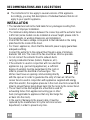
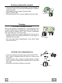
RECOMMENDATIONS AND SUGGESTIONS
The Instructions for Use apply to several versions of this appliance.
Accordingly, you may find descriptions of individual features that do not
apply to your specific appliance.
INSTALLATION
• The manufacturer will not be held liable for any damages resulting from
incorrect or improper installation.
• The minimum safety distance between the cooker top and the extractor hood
is 650 mm (some models can be installed at a lower height, please refer to
the paragraphs on working dimensions and installation).
• Check that the mains voltage corresponds to that indicated on the rating
plate fixed to the inside of the hood.
• For Class I appliances, check that the domestic power supply guarantees
adequate earthing.
Connect the extractor to the exhaust flue through a pipe of minimum
diameter 120 mm. The route of the flue must be as short as possible.
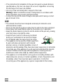
• Do not connect the extractor hood to exhaust ducts
carrying combustion fumes (boilers, fireplaces, etc.).
• If the extractor is used in conjunction with non-electrical
appliances (e.g. gas burning appliances), a sufficient
degree of aeration must be guaranteed in the room in
order to prevent the backflow of exhaust gas. The
kitchen must have an opening communicating directly
with the open air in order to guarantee the entry of clean air. When the
cooker hood is used in conjunction with appliances supplied with energy
other than electric, the negative pressure in the room must not exceed 0,04
mbar to prevent fumes being drawn back into the room by the cooker hood.
• The air must not be discharged into a flue that is used for
exhausting fumes from appliances burning gas or other
fuels (not applicable to appliances that only discharge the
air back into the room).
• In the event of damage to the power cable, it must be
replaced by the manufacturer or by the technical service
department, in order to prevent any risks.
2°

EN 4
4
• If the instructions for installation for the gas hob specify a greater distance
specified above, this has to be taken into account. Regulations concerning
the discharge of air have to be fulfilled.
• Use only screws and small parts in support of the hood.
Warning: Failure to install the screws or fixing device in accordance with
these instructions may result in electrical hazards.
• Connect the hood to the mains through a two-pole switch having a contact
gap of at least 3 mm.
USE
• The extractor hood has been designed exclusively for domestic use to
eliminate kitchen smells.
• Never use the hood for purposes other than for which it has been designed.
• Never leave high naked flames under the hood when it is in operation.
• Adjust the flame intensity to direct it onto the bottom of the pan only, making
sure that it does not engulf the sides.
• Deep fat fryers must be continuously monitored
during use: overheated oil can burst into flames.
• Do not flambè under the range hood; risk of fire.
• This appliance can be used by children aged from
8 years and above and persons with reduced
physical, sensory or mental capabilities or lack of
experience and knowledge if they have been given supervision or instruction
concerning use of the appliance in a safe way and understand the hazards
involved. Children shall not play with the appliance. Cleaning and user
maintenance shall not be made by children without supervision.
• This appliance is not intended for use by persons (including children) with
reduced physical, sensory or mental capabilities, or lack of experience and
knowledge, unless they have been given supervision or instruction
concerning use of the appliance by a person responsible for their safety.

EN 5
5
• “CAUTION: Accessible parts may become hot when used with cooking
appliances.”
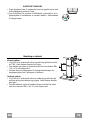
MAINTENANCE
• Switch off or unplug the appliance from the mains supply before carrying out
any maintenance work.
• Clean and/or replace the Filters after the specified time period (Fire hazard).
• The Grease filters must be cleaned every 2 months of operation, or more
frequently for particularly heavy usage, and can be washed in a dishwasher.
• The Activated charcoal filter is not washable and cannot be regenerated,
and must be replaced approximately every 4 months of operation, or more
frequently for particularly heavy usage.
• "Failure to carry out cleaning as indicated will result in a fire hazard".
• Clean the hood using a damp cloth and a neutral liquid detergent.
The symbol on the product or on its packaging indicates that this product
may not be treated as household waste. Instead it shall be handed over to the
applicable collection point for the recycling of electrical and electronic
equipment. By ensuring this product is disposed of correctly, you will help
prevent potential negative consequences for the environment and human
health, which could otherwise be caused by inappropriate waste handling of
this product. For more detailed information about recycling of this product,
please contact your local city office, your household waste disposal service or
the shop where you purchased the product.

EN 6
6
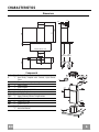
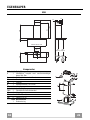
CHARACTERISTICS
Dimensions
64
42
81
Min.
650mm
Min.
650mm
545
730
1000
260
300
470 45
598-698-798-898-1198
108
150
Components
Ref. Q.ty Product Components
1 1 Hood Body, complete with: Controls, Light, Blower,
Filters
2 1 Telescopic Chimney comprising:
2.1 1 Upper Section
2.2 1 Lower Section
9 1 Reducer Flange ø 150-120 mm
15 1 Air Outlet Connection
Ref. Q.ty Installation Components
7.2.1 2 Upper Chimney Section Fixing Brackets
11 6 Wall Plugs
12a 6 Screws 4,2 x 44,4
12c 6 Screws 2,9 x 9,5
Q.ty Documentation
1 Instruction Manual
12b

EN 7
7
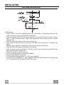
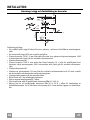
INSTALLATION Wall drilling and bracket fixing
Wall marking:
• Draw a vertical line on the supporting wall up to the ceiling, or as high as practical, at the
centre of the area in which the hood will be installed.
• Draw a horizontal line at 650 mm above the hob. Place bracket 7.2.1 on the wall as shown
about 1-2 mm from the ceiling or upper limit aligning the centre (notch) with the vertical
reference line.
• Mark the wall at the centres of the holes in the bracket.
• Place bracket 7.2.1 on the wall as shown at X mm below the first bracket (X = height of the
upper
chimney section supplied), aligning the centre (notch) with the vertical line.
• Mark the wall at the centres of the holes in the bracket.
• Mark a reference point as indicated at 116 mm from the vertical reference line and 305 mm
above the horizontal reference line.
• Repeat this operation on the other side.
• Drill ø 8 mm holes at all the centre points marked.
• Insert the wall plugs 11 in the holes.
• Fix the brackets using the 12a (4,2 x 44,4) screws supplied.
• Insert the two screws 12a (4,2 x 44,4) supplied in the hood body fixing holes, leaving a gap
of 5-6 mm between the wall and the head of the screw.
11
12a
305 X
116
1÷2
116
650 min.
7.2.1

EN 8
8
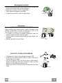
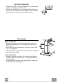
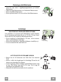
Mounting the hood body
• Before attaching the hood body, tighten the two screws Vr
located on the hood body mounting points.
• Hook the hood body onto the screws 12a.
• Fully tighten the support screws 12a.
• Adjust the screws Vr to level the hood body.
12a
Vr
Connections
DUCTED VERSION AIR EXHAUST SYSTEM
When installing the ducted version, connect the hood to the
chimney using either a flexible or rigid pipe ø 150 or 120
mm, the choice of which is left to the installer.
• To install a ø 120 mm air exhaust connection, insert the
reducer flange 9 on the hood body outlet.
• Fix the pipe in position using sufficient pipe clamps (not
supplied).
• Remove possible charcoal filters.
9
ø 120ø 150
AIR OUTLET – RECIRCULATION VERSION
• Unfasten the 2 screws fixing the upper bracket 7.2.1.
• Fasten the air outlet connector 15 in its place, using the 2
screws removed as above.
• Join the Connector 15 to the Hood canopy outlet using a
rigid or flexible pipe ø150 mm, selection of which is at the
discretion of the installation technician.
• Make sure that the Activated charcoal odour filter has been
fitted.

EN 9
9
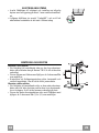
ELECTRICAL CONNECTION
• Connect the hood to the mains through a two-pole switch
having a contact gap of at least 3 mm.
• Remove the grease filters (see paragraph Maintenance) be-
ing sure that the connector of the feeding cable is correctly
inserted in the socket placed on the side of the fan.
Flue assembly
Upper exhaust flue
• Slightly widen the two sides of the upper flue and hook
them behind the brackets 7.2.1, making sure that they are
well seated.
• Secure the sides to the brackets by using the 4 screws 12c
(2,9 x 9,5) supplied.
• Make sure that the outlet of the extensions pieces is aligned
with the chimney outlets.
Lower exhaust flue
• Slightly widen the two sides of the flue and hook them be-
tween the upper flue and the wall, making sure that they
are well seated.
• Fix the lower part laterally to the hood body by using the 2
screws 12c (2,9 x 9,5) supplied.
12b

EN 1
10
L
T1
T2
T3
T4
S1
L
S1
T1 T2 T3 T4
LT3
S1
T2
T1 T4
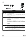
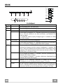
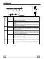
USE
Control panel
Button Led Function
L - Turns the lights on/off at maximum strength.
T1 Fixed Turns the motor on/off at speed one.
Fixed Turns the Motor on at speed two.
T2
- Press and hold the button for approximately 3 seconds, with all the loads turned
off (Motor and Lights), to turn the Activated Charcoal Filter alarm on. The
relevant LED flashes twice to confirm.
To turn the alarm off, press the button again and hold for at least 3 seconds. The
relevant LED flashes once.
Fixed Turns the Motor on at speed three.
T3
Press and hold the button for approximately 3 seconds, with all the loads turned
off (Motor and Lights), to perform a reset of Filter saturation alarm. The LED S1
flashes three times.
Fixed Turns the Motor on at INTENSIVE Speed.
This speed is timed to run for 6 minutes. At the end of this time, the system
returns automatically to the speed that was set before. If it is activated with the
motor turned off, the hood will switch to OFF at the end of the time.
T4
- Press and hold for 3 seconds to enable the remote control, indicated by the LED
flashing twice.
Press and hold for 3 seconds to disable the remote control, indicated by the LED
flashing just once.
Fixed Signals the Metal Grease Filter saturation alarm, indicating that it is necessary to
wash the filters. The alarm is triggered after the Hood has been in operation for
100 working hours.
S1
Flashing When this is activated, it signals the Activated Charcoal Filter saturation alarm,
indicating that the filter must be changed; the Metal Grease Filters must also be
washed. The Activated Charcoal Filter saturation alarm comes
into operation after the Hood has been working for 200 hours.
-

EN 1
11
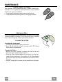
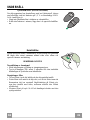
MAINTENANCE
REMOTE CONTROL (OPTIONAL)
The appliance can be controlled using a remote control pow-
ered by a 1.5 V carbon-zinc alkaline batteries of the standard
LR03-AAA type (not included).
• Do not place the remote control near to heat sources.
• Used batteries must be disposed of in the proper manner.
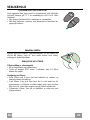
Metal grease filters
These can be washed in the dishwasher, and need to be cleaned
whenever the S1 Led comes on or at least once every 2 months
use, or more frequently if use is particularly intensive.
CLEANING THE FILTERS
Resetting the alarm signal
• Turn the Lights and the Suction Motor off.
• Press T3 and hold for at least 3 seconds, until LED flashes
three times in confirmation.
Cleaning the Filters
• Remove the Filter, pushing it towards the back of the unit
and at the same time pulling downward.
• Wash the filter without bending it, and leave it to dry thor-
oughly before replacing (if the surface of the filter changes
colour over time, this will have absolutely no effect on its ef-
ficiency).
• Replace, taking care to ensure that the handle faces forwards.

EN 1
12
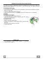
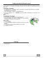
Activated Charcoal Filter (Recirculation Version)
This cannot be washed or regenerated, and must be changed when led S1 starts to flash, or at
least once every 4 months. The Alarm signal, if it has been activated, only appears when the
Suction motor is turned on.
Activating the alarm signal
• In Recirculation Version Hoods, the Filter Saturation Alarm must be activated on installa-
tion or at a later date.
• Turn the Lights and the Suction Motor off.
• Press button T2 and hold it for 5 seconds until the LED flashes twice in confirmation:
CHANGING
Resetting the alarm signal
• Turn the Lights and the Suction Motor off.
• Press T3 and hold for at least 3 seconds, until LED flashes
three times in confirmation.
Changing the Filter
• Remove the Metal Grease Filter
• Remove the saturated Activated charcoal filter, using the hooks
provided.
• Fit the new Filter, hooking it into place.
• Fit the Grease filter.
Lighting unit
• For replacement contact technical support ("To purchase
contact technical support").

NO 1
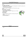
13
ANBEFALINGER OG FORSLAG
Bruksveiledningen refererer til ulike apparatmodeller. Du kan derfor finne
beskrivelser av enkelte egenskaper som ikke gjelder ditt apparat.
INSTALLASJON
• Produsenten er ikke ansvarlig for eventuelle skader som skyldes feil
installasjon eller bruk.
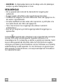
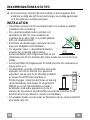
• Minste sikkerhetsavstand mellom platetopp og
kjøkkenvifte er 650 mm (noen modeller kan
monteres ved lavere høyde. Se avsnittet om
arbeidsmål og installasjon).
• Kontroller at nettspenningen stemmer med
spenningen oppgitt på merkeplaten på innsiden av
kjøkkenviften.
• For apparater i klasse I må du kontrollere at
hjemmets strømnett er jordet.
Koble kjøkkenviften til røkkanalen med et rør med en diameter på min. 120
mm. Røret må være så kort som mulig.
• Ikke koble kjøkkenviften til røkkanaler for utslipp av forbrenningsrøk (f.eks.
fra kjeler, peiser, osv.).
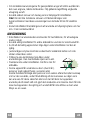
• Hvis kjøkkenviften brukes sammen med apparater
som ikke bruker strøm (f.eks. gassapparater), må
det garanteres en god ventilasjon i rommet for å
unngå retur av forbrenningsgassen. Kjøkkenet må
ha en åpning direkte til utsiden for å sikre inntak
av frisk luft. Når kjøkkenviften brukes sammen
med apparater som ikke bruker strøm, må ikke det
negative trykket i rommet overstige 0,04 mbar for
å unngå en retur av røkene.
• Hvis nettkabelen ødelegges, må den byttes ut av produsenten eller
servicesenteret for å unngå enhver risiko.
2°

NO 1
14
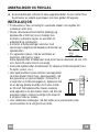
• Hvis installasjonsinstruksjonene for gassplatetoppen spesifiserer en større
avstand enn angitt ovenfor, må du overholde dette. Følg alle
bestemmelsene for luftutløp.
• Bruk kun skruer og beslag som passer til kjøkkenviften.
Advarsel: Manglende installasjon av skruer eller festeanordninger i samsvar
med disse instruksjonene kan medføre risiko for elsjokk.
• Koble kjøkkenviften til strømnettet med en topolet bryter med en
kontaktåpning på minst 3 mm.
BRUK
• Kjøkkenviften er kun utviklet til husholdningsbruk for å fjerne matos fra
kjøkkenet.
• Bruk aldri kjøkkenviften til annet formål enn tiltenkt bruk.
• Gå aldri fra en tent brenner uten at det står en gryte oppå mens
kjøkkenviften er i funksjon.
• Reguler flammestyrken slik at flammen kun dekker grytebunnen og ikke
stikker utover kantene.
• Vær alltid veldig oppmerksom ved frityrsteking,
fordi den varme oljen kan ta fyr.
• Ikke flambér under kjøkkenviften, fordi det kan
utvikles brann.
• Barn (over 8 år) eller personer med nedsatte
fysiske, sensoriske eller psykiske evner, eller
personer uten erfaring og kunnskap må kun bruke apparatet dersom de får
tilsyn eller opplæring i en sikker bruk av apparatet og farene knyttet til
bruken. Ikke la barn leke med apparatet. Rengjøring og vedlikehold må ikke
utføres av barn med mindre de er under tilsyn.

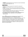
NO 1
15
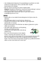
• ADVARSEL: De tilgjengelige delene kan bli veldige varme når platetopper,
komfyrer og andre kokeapparater er i bruk.
VEDLIKEHOLD
• Slå av apparatet eller koble det fra strømnettet før rengjøring eller
vedlikehold.
• Rengjør og/eller skift ut filtrene etter oppgitt intervall (brannfare).
• Fettfiltrene må rengjøres hver andre måned eller oftere ved hyppig bruk. De
kan vaskes i oppvaskmaskin.
• Det aktive kullfilteret kan ikke vaskes eller regenereres, og må byttes ut ca.
hver fjerde måned, eller oftere ved hyppig bruk.
• "Det er fare for brann hvis rengjøringen ikke utføres i henhold til
instruksjonene."
• Bruk kun en fuktig klut og et mildt rengjøringsmiddel til rengjøringen av
kjøkkenviften.
Symbolet på apparatet eller emballasjen angir at apparatet ikke skal kastes
sammen med vanlig husholdningsavfall. Apparatet må leveres til et
innsamlingssenter for resirkulering av elektrisk og elektronisk materiale. Ved å
kassere dette apparatet på riktig måte, bidrar du til å forhindre de negative
virkningene på miljøet og menneskehelsen som kan forårsakes av en feilaktig
avfallshåndtering av dette apparatet. For mer informasjon om gjenvinning av
dette apparatet, kontakt kommunen, renovasjonsselskapet eller forhandleren
hvor apparatet ble kjøpt.

NO 1
16
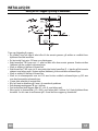
EGENSKAPER
Dimensjoner
64
42
81
Min.
650mm
Min.
650mm
545
730
1000
260
300
470 45
598-698-798-898-1198
108
150
Deler
Ref. Antall Produktets deler
1 1 Kjøkkenviftens hoveddel komplett med: Kontroller, lys,
vifteenhet, filtre
2 1 Uttrekkbart røkrør; består av:
2.1 1 Øverste røkrør
2.2 1 Nederste røkrør
9 1 Reduksjonsflens med en diameter på 150-120 mm
15 1 Luftutløpskopling
Ref. Antall Installasjonsdeler
7.2.1 2 Festekonsoller til øverste røkrør
11 6 Ekspansjonsplugger
12a 6 Skruer 4,2 x 44,4
12c 6 Skruer 2,9 x 9,5
Antall Dokumentasjon
1 Bruksveiledning
12b

NO 1
17
INSTALLASJON
Boring av hull i veggen og festing av konsollene
Tegn opp følgende på veggen:
• En vertikal linje helt opp til taket eller til den øverste grensen, på midten av området hvor
kjøkkenviften skal monteres.
• En horisontal linje min. 650 mm over platetoppen.
• Støtt konsollen 7.2.1 som vist 1-2 mm fra taket eller den øverste grensen. Sentrer midten
(hakkene) på den vertikale referanselinjen.
• Merk av midten til hullene til konsollen.
• Støtt konsollen 7.2.1 som vist X mm under den første konsollen (X = høyden på det øverste
røkrøret som følger med). Sentrer midten (hakkene) på den vertikale referanselinjen.
• Merk av midten til hullene til konsollen.
• Merk av et referansepunkt som vist 116 mm fra den vertikale referanselinjen og 305 mm
over den horisontale referanselinjen.
• Gjenta dette arbeidet på motsatt side.
• Bor hull med en diameter på 8 mm i de avmerkede punktene.
• Sett ekspansjonspluggene 11 inn i hullene.
• Fest konsollene med skruene 12a (4,2 x 44,4) som følger med.
• Skru inn de to skruene 12a (4,2 x 44,4) som følger med i hullene for å feste kjøkkenviftens
hoveddel. La det være et mellomrom på 5-6 mm mellom veggen og skruehodet.
11
12a
305 X
116
1÷2
116
650 min.
7.2.1

NO 1
18
Montering av kjøkkenviftens hoveddel
• Før du hekter på kjøkkenviftens hoveddel, må du stramme de
to skruene Vr som er plassert på hektepunktene til kjøkken-
viftens hoveddel.
• Hekt kjøkkenviftens hoveddel på skruene 12a.
• Stram til skruene 12a.
• Skru på skruene Vr for å nivellere kjøkkenviftens hoveddel.
12a
Vr
Tilkoplinger
LUFTUTLØP, UTSUGNINGSVERSJON
Når du skal installere en kjøkkenvifte i utsugningsversjon må
du kople kjøkkenviften til utløpsrørene med et hardt eller flek-
sibelt rør med en diameter på 150 eller 120 mm. Installatøren
kan velge hvilket rør som er mest egnet.
• Dersom du bruker et rør med en diameter på 120 mm til til-
koplingen må du føre reduksjonsflensen 9 inn på utløpet til
kjøkkenviftens hoveddel.
• Fest røret med egnede slangeklemmer. Disse delene følger
ikke med kullfilter.
9
ø 120ø 150
LUFTUTLØP FOR FILTRERINGSVERSJON
• Løsne de to skruene som fester den øverste konsollen 7.2.1.
• Fest i stedet luftutløpskoblingen 15 med de to skruene som
ble fjernet.
• Koble koblingen 15 til utløpet fra kjøkkenviftens hoveddel
med et rør eller en slange med en diameter på 150 mm (etter
eget valg).
• Kontroller at det aktive kullfilteret er montert.

NO 1
19
ELEKTRISK TILKOPLING
• Kople kjøkkenviften til strømnettet med en topolet bryter med
en kontaktåpning på minst 3 mm.
• Fjern fettfiltrene (se avsnittet Vedlikehold) og kontroller at ko-
plingsstykket til nettkabelen er korrekt innført i stikkontakten
til sugesystemet.
Montering av røkrøret
Øverste røkrør
• Utvid litt de to kantene på sidene og hekt dem på bak konsolle-
ne 7.2.1. Lukk kantene deretter helt igjen.
• Fest kantene på sidene av konsollene med de fire skruene 12c
(2,9 x 9,5) som følger med.
• Forsikre deg om at åpningene til forlengelsesledningen for
koplingen passer inn i åpningene til røkrøret.
Nederste røkrør
• Utvid litt de to kantene på sidene av røkrøret og hekt dem på
mellom det øverste røkrøret og veggen. Lukk kantene deretter
helt igjen.
• Fest den nederste siden til kjøkkenviftens hoveddel fra siden
med de to skruene 12c (2,9 x 9,5) som følger med.
12b

NO 2
20
L
T1
T2
T3
T4
S1
L
S1
T1 T2 T3 T4
LT3
S1
T2
T1 T4
BRUK
Kontrollpanel
Knapp LED Funksjon
L - Slår belysningen på/av ved maks styrke.
T1 Tent konstant Slår motoren på/av ved den første hastigheten.
Tent konstant Slår motoren på ved den andre hastigheten.
T2
- Hvis du trykker på knappen i ca. 5 sekunder når motoren og belysningen er
slått av, aktiveres alarmen for de aktive kullfiltrene, og tilhørende LED
blinker to ganger.
For å deaktivere alarmen, trykk på knappen igjen i 5 sekunder til LEDen
kun blinker én gang.
Tent konstant Slår motoren på ved den tredje hastigheten.
T3
- Hvis du trykker på knappen i ca. 3 sekunder når motoren og belysningen er
slått av, tilbakestilles alarmen, og LEDen S1 blinker 3 ganger.
Tent konstant Slår motoren på ved den INTENSIVE hastigheten.
Kjøkkenviften fungerer med den intensive hastigheten i 6 minutter. Når
tiden er utløpt, går kjøkkenviften automatisk tilbake til den tidligere valgte
hastigheten. Hvis denne hastigheten aktiveres mens motoren er slått av, slås
kjøkkenviften av når tiden er utløpt.
T4
- Hvis du trykker på knappen i 5 sekunder, aktiveres fjernkontrollen og
tilhørende LED blinker to ganger.
Hvis du trykker på knappen i 5 sekunder, deaktiveres fjernkontrollen og
tilhørende LED blinker kun én gang.
Tent konstant Signalerer at de metalliske fettfiltrene er mettet og må vaskes.
Alarmsignalet gis etter at kjøkkenviften har fungert i 100 timer.
S1
Blinker Når den er aktivert, signalerer den at det aktive kullfilteret er mettet og må
byttes ut. Samtidig må de metalliske fettfiltrene vaskes. Alarmsignalet for
mettet aktivt kullfilter gis etter at kjøkkenviften har fungert i 200 timer.
Sidan laddas ...
Sidan laddas ...
Sidan laddas ...
Sidan laddas ...
Sidan laddas ...
Sidan laddas ...
Sidan laddas ...
Sidan laddas ...
Sidan laddas ...
Sidan laddas ...
Sidan laddas ...
Sidan laddas ...
Sidan laddas ...
Sidan laddas ...
Sidan laddas ...
Sidan laddas ...
-
 1
1
-
 2
2
-
 3
3
-
 4
4
-
 5
5
-
 6
6
-
 7
7
-
 8
8
-
 9
9
-
 10
10
-
 11
11
-
 12
12
-
 13
13
-
 14
14
-
 15
15
-
 16
16
-
 17
17
-
 18
18
-
 19
19
-
 20
20
-
 21
21
-
 22
22
-
 23
23
-
 24
24
-
 25
25
-
 26
26
-
 27
27
-
 28
28
-
 29
29
-
 30
30
-
 31
31
-
 32
32
-
 33
33
-
 34
34
-
 35
35
-
 36
36


Røroshetta LYRA 60 KJØKKENVENTILATOR, SVART Bruksanvisning
- Kategori
- Mixer / matberedare tillbehör
- Typ
- Bruksanvisning
på andra språk
Relaterade papper


Andra dokument
-
Aeg-Electrolux DD9963-M Användarmanual
-
 Franke Consumer Products FNE 905 XS ECS Användarmanual
-
 Franke Consumer Products FSL 905 WH/XS ECS Användarmanual
-
 Franke Consumer Products FGL 6104 XS ECS Användarmanual
-
 Franke Consumer Products FCH 906 XS ECS Användarmanual
-
Aeg-Electrolux DD6690-M Användarmanual
-
HUSQVARNA-ELECTROLUX QFC90155X Användarmanual
-
Grundig GDSP5470DXSCH KJØKKENVENTILATOR Bruksanvisning


